1
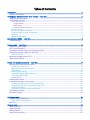
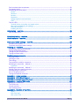
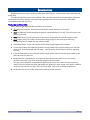
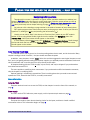
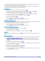
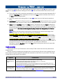
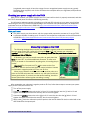
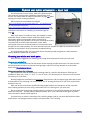
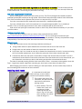
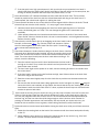
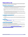
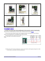
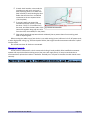
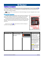
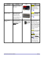
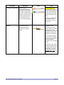
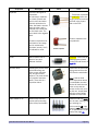
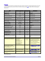
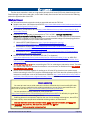
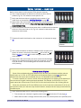
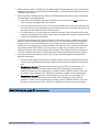
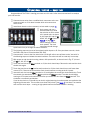
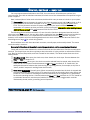
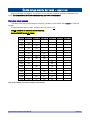
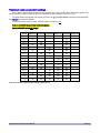
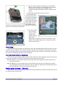
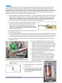
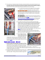
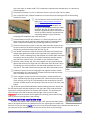
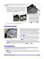
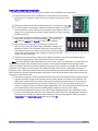
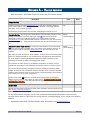
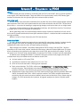
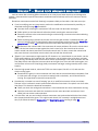
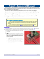
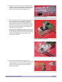
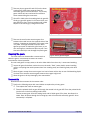
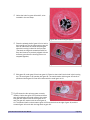
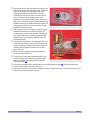
Insert a small screwdriver and gently pry a clip outward. When it opens, slide the cover away slightly, then release the other clip. The plastic case is slippery, so the screwdriver might slip out before the latch releases. Keep trying. With both clips released, pull the cover off. Fig. 30 shows what you’ll see with the cover removed. The mechanism is completely enclosed and contains the stepper motor (copper wire coil) Fig. 29: Opening a movement. and the gears. It rests freely inside the case; there are no screws to remove or wires to disconnect. Notice the metal clips in the battery compartment. Lift the movement out of the case and set it aside. Tap the case Fig. 30: Movement in the case. against a table to loosen both battery clips, or pull them loose with your fingers or pliers (Fig. 31). Discard the battery clips – they are not used in fast-time movements. Fig. 31: Battery clips loose. Terminology The clock movement consists of an outer black "case" with a threaded brass bushing on the front, and a removable cover on the back. The movement's motor and gears are contained in a clear plastic "housing," with a circuit board (PCB) on top, that rests inside the case when the movement is assembled. These terms are used in the following instructions to avoid confusion. Two methods to modify a movement There are two ways to modify a Q80 movement. Both methods involve soldering a resistor and two wires to the motor, but differ in how these components connect to the motor terminals. With Method 1, you unsolder and remove the entire PCB, then solder the resistor and wire to the bare motor terminals. With Method 2, you use a hobby saw to cut the PCB and remove most of it, leaving only a narrow sliver still attached to the motor terminals. Then you solder the resistor and wire to the terminals on the remaining sliver. Thanks to Julian Garner for this idea. Modifying the movement – Method 1 Work carefully. You will unsolder and remove the circuit board (PCB), then solder a resistor and a wire to the exposed motor coil terminals. FCC4 Fast Clock Controller User Manual Page 39