1
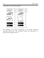
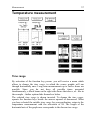
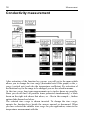
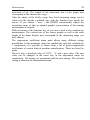
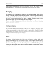
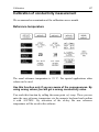
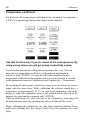
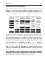
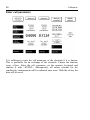
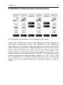
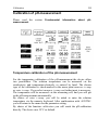
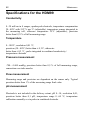
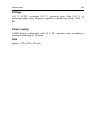
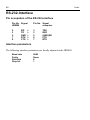
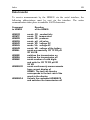
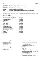
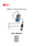
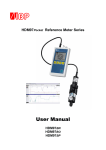
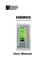
HDM99
Dialysis Measuring System
User Manual
The information contained in this documentation can undergo changes
without special announcement. IBP Instruments GmbH takes no
responsibility with this document. The contained software is being
delivered on the basis of a general licence contract or in single license. Use
or reproduction of the software is allowed only in agreement with the
contractual arrangements. Whoever transfers this software and/or this
manual on magnetic tape, diskette or any other media, except for the
purpose of own use, without written authorization of the IBP Instruments
GmbH, is liable to prosecution.
Copyright (C) 1996-2000, IBP Instruments GmbH.
All rights reserved
Publisher:
IBP Instruments GmbH
Sutelstr. 7A
D 30659 Hannover
Manual author:
Werner Pfingstmann
3rd Edition August 2000
IBP Instruments Inc
635 South Orange Avenue.
Sarasota, FL 34236
Attention
Read these safety instructions before using the HDM99
•
Please read the manual before using the HDM99.
•
Keep away the device from unauthorized persons.
•
Never use the HDM99 with connected battery charger
on a dialysis machine to which a patient is connected.
•
Operate the instrument only in a dry environment, and
do not touch it with damp hands. Ensure that no fluids
intrude into the interior of the device or into the sockets
at the front.
•
Apply a protection filter to the nozzle for the pressure
measurement .
•
Avoid a discharge of static electricity over the sockets.
It could lead to the destruction of your measuring
device. Before touching the sockets and lines that are
connected with them, keep an eye on the discharging of
static electricity.
•
Voltages above 40V can be dangerous. Take extreme
care while working with higher voltages.
•
To avoid electrical shocks, and/or damage to your
measuring system, do not apply excess voltages above
40 V to the instrument.
•
Only calibrate the device if you have understood the
consequences to their full extent.
•
Do not open the device.
DELIVERY EXTENT....................................................................................... 6
EC-CONFORMITY DECLARATION............................................................. 7
GUARANTEE DIRECTIVES........................................................................... 8
INTRODUCTION ............................................................................................. 9
CONNECTIONS ................................................................................................ 10
CHARGE CONNECTION .................................................................................... 11
TURNING ON THE DEVICE ................................................................................ 13
MAIN MENU ................................................................................................... 13
MEASUREMENT .............................................................................................. 15
TEMPERATURE MEASUREMENT............................................................. 17
CONDUCTIVITY MEASUREMENT ............................................................ 18
CONDUCTIVITY AND TEMPERATURE MEASUREMENT.................... 21
FURTHER POSSIBLE MEASUREMENTS .................................................. 25
PH MEASUREMENT..................................................................................... 26
PH-CALIBRATION IN THE MEASURING MODE
.................................................... 30
FLOW MEASURING ..................................................................................... 31
MANAGEMENT OF DIFFERENT SENSORS ........................................................... 31
COUNTER ....................................................................................................... 34
POOL MENU .................................................................................................. 35
VOLTAGE MEASUREMENT - PLOTTER .................................................. 36
VOLTAGE MEASUREMENT - OSCILLOSCOPE ...................................... 38
BATTERY VOLTAGE ................................................................................... 40
INSTALLATION............................................................................................. 41
LANGUAGE .................................................................................................... 41
SWITCH-OFF TIME ........................................................................................... 41
ADJUST-RESET ............................................................................................... 42
CALIBRATION OF THE HDM99 ................................................................. 43
ADJUSTMENT ................................................................................................. 43
CALIBRATION OF TEMPERATURE MEASUREMENT ............................................. 45
CALIBRATION OF CONDUCTIVITY MEASUREMENT ............................................. 47
CALIBRATION OF THE PRESSURE MEASUREMENT .............................................. 51
CALIBRATION OF PH-MEASUREMENT............................................................... 53
PH-CALIBRATION........................................................................................ 54
CALIBRATION OF FLOW............................................................................ 55
CALIBRATION OF THE VOLTAGE MEASUREMENT ............................ 57
MAINTENANCE AND CARE OF THE HDM99........................................... 58
STORAGE ........................................................................................................ 58
CLEANING ...................................................................................................... 59
CALIBRATION INTERVALS ............................................................................... 60
SPECIFICATIONS FOR THE HDM99.......................................................... 62
RS-232-INTERFACE ...................................................................................... 64
HDMCMO
STARTS BACKGROUND MEASUREMENT........................ 66
12964.12/ 24.7/ 750/ 7.00/ -0.03/ 0.05/6.12/1200/1000/79131/999999 + CR LF à
73 SIGNS......................................................................................................... 66
6
Delivery extent
The hardware of HDM99 consists of:
HDM99
Combined electrode conductivity / temperature
Flow-through connector for conductivity/temperature probe
Pressure measuring tube
Voltage measuring cables
Count input measuring cables
Battery charger
Standard solution conductivity 13,63 mS/cm
The documentation of HDM99 consists of this manual.
If you should miss anything, please contact your supplier.
Introduction
Introduction
7
EC-Conformity Declaration
Hereby we declare that the HDM99 corresponds to the basic requirements
for protection according to the guidelines of the board for the assimilation
of legal regulations about electro-magnetic compatibility (89/336/EWG) of
the member states.
For the rating of the devices in view to their electro-magnetic compatibility
the following norms have been used:
Emission:
Immission:
EN 55022 Class B
IEC 801-3 Criterion A
IEC 801-2 Criterion A
IEC 801-4 Criterion B
This declaration is responsibly given for
IBP Instruments GmbH
Sutelstr. 7A
30659 Hannover
by
Dipl. Ing. Werner Pfingstmann
Managing director
Hannover, September 30, 1996
8
Introduction
Guarantee directives
The existing product is a technical device which contains only modern
electronic components. During the manufacturing exclusively first choice
parts are used. Each device undergoes extensive tests before delivery.
IBP warrants that the device is free from defects in material and
workmanship for a period of 12 months beginning at the date of delivery.
Excluded from the guarantee are damages by improper treatment,
inappropriate usage, by connecting to excess voltages, modifications in the
device or through risks which the user has to cover by a suitable insurance
(fire, water, intrusion, robbery etc.)
All conceivable measures were met to assure the accuracy of this productdocumentation. IBP cannot grant any guarantee for the completeness and
the accuracy of the software and the documentation. IBP is not responsible
for damages (including, but not limited to, damages for loss of business
profits, business interruption, loss of data, and other special, incidental or
consequential damages) which emerge through the usage of the product by
the customer.
Introduction
9
Introduction
HDM99 is an innovative computer processed measuring system with which
nine parameters can be measured:
Conductivity
Temperature
Pressure
pH
Flow
Voltage
Frequency
Period time
Events
The device has been developed for the usage on dialysis machines, but is
also usable in the labor in the environmental measuring technology.
The handling is uncomplicated and follows the motto: Only the manual is
necessary in cases of doubt.
The entire handling is led by dialogues. The calibration of the device by the
user is simple and gives no problems.
The display of measurement results is available n numerical and also in
graphical form.
Via the serial interface the measurements can be called independently of
the current display, and further processed or presented on a PC. For the
fault location at dialysis machines IBP has developed a program that
presents and processes measurements of the HDM99 and of the machine
together. Provided that the dialysis machine is equipped with an interface
according to RS232- or RS485-standard. Drivers for different instruments
are available or in preparation. The program runs under MS-Windows and
is therefore easy to operate.
10
Introduction
Connections
voltage
_
conductivity
pressure
and temperature
pH
+
Voltage
The sockets are intended only for AC and DC voltages up to 40 V. They
are protected up to 80 V.
Conductivity / Temperature
The conductivity measurement is designed for quadropole technology.
Please use exclusively the electrode delivered with the device by IBP.
Pressure
To avoid damages at the pressure probe or inaccuracies in measurement,
ensure that no fluids intrude into the device.
We recommend the application of a protection filter.
pH
The input bushes are intended exclusively for pH-electrodes. Other signals
may destroy the device.
Introduction
11
Flow
The connection is to be found at the right side of the device.
(8pol. connector)
Frequency, Periodicity and Events
The connection on the right side of the device is also used for the
measuring of the flow. The incoming voltage range is +5...+24 V. The form
of the signal should be of a rectangular form and has to be positive.
Charge connection
The charge connection is found at the right side of the device. The
connection is provided with 12 V / 500 mA by the included battery charger.
For safety reasons never use the HDM99 with connected
battery charger on a dialysis machine to which a patient is
connected.
12
Introduction
Combined electrode in Hansen-connector
In the flow-through mode the connector is
suitable for measuring pressure, temperature
and conductivity. In the dip-in mode
temperature and conductivity can be
measured. The preferential position of the
Hansen-connector is vertical, the axial
supply shows downward.
In the flow-through mode the axial supply is
used as input and the radial supply as output
(see illustration). The pressure probe in
HDM99 is fastened to the radial connection
above the input. Before any measurements
you must shake the connector to assure that
any air within the system escapes.
For the dip-in mode open the screw cap at
the upper end of the connector and extract
the combined electrode. You must not
remove the tube covering the probe carrier.
Dip the electrode into the media up to a
level above the
borings in the covering
tube. By moving the electrode you assure
that the contained air can
escape and the
temperature is well balanced.
Do not touch the surface of the electrode with your
fingers.
Introduction
13
Turning on the device
The device is switched on and off with the keys ON and OFF. In addition
to that, the device automatically switches off when the accumulator is
exhausted, or after the elapsing of an adjustable time.
Main menu
After switching on the device you receive an information menu for approx.
two seconds. After that the system goes back to the last setting. In some
cases you will receive the following main menu.
Activation of the function keys leads to
display of the info-menu
display of the measuring menu
display of the calibration menu
display of the installation menu
14
Introduction
Info
From the root menu via info you receive the following information:
There are device specific data like product name, software version and
version date as well as the serial number of your HDM99.
Measurement
Measurement
From the main menu over measuring you will receive the following menu:
15
16
Measurement
Examples for measurement displays
F1
F1
F2
F2
F3
F3
F4
F4
F5
F5
F6
F6
The handling of all menus corresponds to the already explained
operating instructions. The individual menus and sub-menus are
presented and explained below.
Measurement
17
Temperature measurement
Time range
By activation of the function key param. you will receive a menu which
allows to change the time range, in which the course graphic will run
through horizontally once. Long term measurements up to twelve hours are
possible. Since you do not have all possible times presented
simultaneously, a black beam on the right side shows that above, or - like in
the example - further options hide themselves below.
The selected time range is shown inverted. To change the time range,
operate the function keys beside the arrows upward or downward. When
you have selected the suitable time range for your application, return to the
temperature measurement with the activation of ok. The length of the
horizontal axis of the graph now corresponds to the chosen time range.
18
Measurement
Conductivity measurement
After activation of the function key param. you will get to the menu which
allows you to change the time range (horizontal axis of the graph) or the yrange (vertical axis) and also the temperature coefficient. By activation of
the function key for the range to be changed you see the selection menus.
At the time range long term measurements up to twelve hours are possible.
Since you do not have all possible times presented simultaneously, a black
beam on the right side shows that above, or - like in the example -, further
options hide themselves below.
The selected time range is shown inverted. To change the time range,
operate the function keys beside the arrows upward or downward. When
you have selected the suitable time range for your application, return to the
temperature measurement with the
Measurement
19
activation of ok. The length of the horizontal axis of the graph now
corresponds to the chosen time range.
After the choice of the field y-range four fixed measuring ranges can be
selected in the already explained way with the function keys beside the
arrows. If you choose > auto <, the HDM99 automatically adjusts the
measuring range so that an optimal graphic representation of the running
measurement is assured.
With activation of the function key ok you arrive back in the conductivity
measurement. The vertical axis of the course graphic as well as the scale
length of the beam display now correspond to the measuring range you
have chosen.
The temperature coefficient menu point allows many different setting
possibilities. In the parameter menu for conductivity and also conductivity
+ temperature, it is possible to choose from a list of preset temperature
coefficients of various dialysis machine manufacturers. These are listed by
name.
There is also a standard value of 2.07% / °C and a user value. The user
value can be changed in the usual way in the adjustment menu for
conductivity. All settings are permanent until the next change. The selected
setting is shown in the measurement menu.
20
Measurement
Basic information about the temperature
coefficient
The temperature coefficient in conductivity measurement is an important
subject that is frequently neglected. The conductivity of a solution changes
with the temperature. As the temperature rises, the conductivity of the
measurement solution increases also. In order to arrive at meaningful
measured values, the display value is compensated to 25°C. Expressed in
another way, the display is always converted to a solution temperature of
25°C. The temperature coefficient with which the display is compensated is
expressed in % / °C.
However, different solutions now unfortunately also have different
temperature coefficients. For the display to be precise, the measuring unit
must therefore be set to the temperature coefficient of the current solution.
The average temperature coefficient for dialysate is 2.07% / °C. A value of
1.97% / °C is frequently used for natural water.
To perfect the chaos, the different manufacturers of dialysis machines also
use different temperature coefficients in their machines.
Baxter
Braun
FMC
Gambro
Hospal
Nikkiso
Bicarbonat
Total conductivity
2,20 %/°C
2,00 %/°C
2,10 %/°C
1,80 %/°C
2,07 %/°C
2,02 %/°C
2,05 %/°C
This gives rise to the following recommendations:
1.
You have machines from one manufacturer only:
Use the temperature coefficient that the dialysis machine uses for
compensation
2.
You have machines from different manufacturers:
Use as a temperature coefficient a mean value.
2.07% / °C is recommended for this.
Measurement
Conductivity and temperature
measurement
21
22
Measurement
Measuring range conductivity
After the choice of the field y-range four fixed measuring ranges can be
selected in the already explained way with the function keys beside the
arrows. If you choose > auto <, the HDM99 automatically adjusts the
measuring range, this way an optimal graphic representation of the running
measurement is assured.
By activating the function key ok you will get back to the conductivity and
temperature measurement. The vertical axis of the course graphic, as well
as the scale length of the beam display, now correspond to the measuring
range you have chosen.
The temperature coefficient menu point allows many different setting
possibilities. In the parameter menu for conductivity and also conductivity
+ temperature, it is possible to choose from a list of preset temperature
coefficients of various dialysis machine manufacturers. These are listed by
name.There is also a standard value of 2.07% / °C and a user value. The
user value can be changed in the usual way in the adjustment menu for
conductivity. All settings are permanent until the next change. The selected
setting is shown in the measurement menu.
Measurement
23
Pressure measurement
Time range
After activation of the function key time range you will get to a menu
which allows to change the time range (horizontal axis of the graph).
Long term measurements up to twelve hours are possible. Since you do not
have all possible times presented simultaneously, a black beam on the right
side shows that above, or - like in the example -, further options hide
themselves below.
The selected time range is shown inverted. To change the time range,
operate the function keys beside the arrows upward or downward. When
you have selected the suitable time range for your application, return to the
temperature measurement with the activation of ok. The length of the
horizontal axis of the graph now corresponds to the chosen time range.
24
Measurement
Unit
The unit for the pressure measurement can be chosen. The values are
converted when the unit is changed. A new calibration is not necessary.
The selection of the unit is done in the familiar way with the function keys
beside the arrows. With ok you return to the pressure measurement, where
now the results will be shown in the newly chosen unit.
Taring
Caused by drift of the pressure probe, the pressure display may sway
slightly around zero. With the function tare the display is set to zero. You
must not apply pressure to the HDM99 during this function. This is assured
when the pressure tube is not connected. Then the environmental pressure
represents zero.
The choice of the function key tare results in the reset of the display to zero
and the automatic return to the pressure measurement.
Measurement
25
Further possible measurements
With the option other channels you can shift to a second measuring menu
where you have the choice between two different modes of voltage
measurement: the test for pH-value and the control of the charging state of
the accumulators.
If you would like to return to the first measuring menu with conductivity,
temperature and pressure measurement choose other channels again.
26
pH Measurement
Measurement
Measurement
27
Time range
By activation of the function key param. you will receive a menu which
allows to change the time range in which the course graphic will run
through horizontally once. Long term measurements up to twelve hours are
possible. Since you do not have all possible times presented
simultaneously, a black beam on the right side shows that above, or -like in
the example- further options hide themselves below.
The selected time range is shown inverted. To change the time range,
operate the function keys beside the arrows upward or downward. When
you have selected the suitable time range for your application, return to the
temperature measurement with the activation of ok. The length of the
horizontal axis of the graph now corresponds to the chosen time range.
28
Measurement
Temperature compensation pH-measurement
For the temperature calibration of the pH-measurement the device offers
two possibilities. The solution temperature can be measured via the
conductivity and temperature electrode, or entered by hand. The chosen
kind of the calibration is check-marked in the menu point measure t-comp
or enter t-comp. If you choose measure t-comp. no further input is
necessary. The temperature will be measured via the measuring cell.
By choice of enter t-comp. you will be asked to enter the solution
temperature via the numeric keyboard. After confirmation with >ENTER<
you will return to the menu for the parameter setting
Fundamental information about pH-measurement
For the measurement of the pH-value a combined electrode is used. pH
electrodes are combinations of one reference electrode and one measuring
electrode in a glass tube.
The pH-value in the dialysate is measured by an unbreakable pH-electrode.
The glass body is protected with a plastic coat and due to the jellyelectrolyte-filling maintenance-free. This electrode` s diaphragm must be
stored in 3 mol/l KCl-solution. The protection hood must be refilled every
three to four weeks.
Measurement
29
For pH-measurement in untreated desalinated water a particular electrode is
necessary. This glass electrode is optionally available and has a 1 mol/l KCl
reference electrolyte. The diaphragm of this electrode must be stored in
1 mol/l KCl-solution.
Before usage the electrode must be checked on exterior damage and glass
crash. Crusts caused by leaking electrolyte can be removed easily by
rinsing. The sample volume should be 100 ml dialysate or 1 l of untreated
water. The sample volume is being led to the bottom of the vessel with a
tube or hose for coming as little as possible into contact with air. The pHvalue must be measured immediately in the same vessel. You have to make
sure that the display stabilizes before the value is read. In stirred solutions
the response rate is faster, the value, however, must be measured at resting
fluid.
The pH-electrode must be dabbed only and never rubbed dry. The rubbing
destroys the jelly layer on the glass surface which results in a longer
response time of the electrode.
Due to the special electrode, for pH-measurement in untreated water further
points need to be paid attention to: air bubbles in the membrane space of
the electrode can be removed easily by shaking movements similar to a
clinical thermometer. The reference electrolyte in this electrode can be
refilled. Make sure that the refill cap is sealed with the rubber hood. The
level of the reference electrolyte must always be sufficiently large.
Before the measurement the rubber hood must be removed, since otherwise
no internal pressure compensation occurs. On the lower shaft of the
electrode a plastic part is to be found which must always remain freely
movable on the shaft. If the mobility of the plastic part should be restricted
it can be released by rinsing with lukewarm water. This plastic part
conceals an opening in the glass which must be covered always.
Pressure and currents have considerable influence on the pHmeasurements. Therefore, it is necessary to accomplish the pHmeasurement in a resting solution at environmental pressure.
30
Measurement
pH-calibration in the measuring mode
Calibration
Before the adjustment the kind of temperature calibration must be set
already.
Prepare two buffer solutions. The two buffers should not differ more than
two activation decades. Choose, for example, pH4 and pH6. Carefully
remove the protection hood for the measurement. Rinse and dab the pH
electrode with distilled water before dipping it into the buffer. If necessary
wash and dry the temperature sensor likewise, and put it into the measuring
beaker. Wait until the display remains stable, then enter the pH-value via
the numeric keyboard. Confirm your input with > ENTER <. Then wash
and dry the electrode and dip it into the second buffer. When the value of
the second buffer is entered, the display shows the actual calibration. If
thereby the graduation (grad) is lower than 85%, the electrode could be
worn out and must be replaced by a new one.
If you try to enter two equal values the reference invalid data appears after
confirming with ok; at correct input the data will be saved, and you will
return to the menu for the parameter setting.
Measurement
31
Flow measuring
The current flow rate and the amount of flown liquid will be shown. The
amount of flown liquid can be restored to zero by pushing Reset.
Management of different sensors
For the measuring of the flow different sensors will be used according to
the measuring unit. The HDM99 governs up to 15 different sensors. For
detecting the different sensors a code is put on them. This code is used for
the internal choice of calibration data. The number of the connected sensors
will be shown in the display.
Any sensor can be used which has an output signal that delivers a
frequency proportional to the flow running. The amplitude at the entrance
of the HDM99 may have a range of 5...24 V. For the current supply of the
sensors 5 V DC/ 10 mA are available at the connection of the flow
measuring.
32
Measurement
Connection occupancy of the plug connection for the
flow measurement
Pin
1
2
3
4
5
6
7
8
Meaning
currency supply sensor 5 V/ max 10 mA
signal input 5...24 V max 1 MHz
GND
code input 0
code input 1
code input 2
code input 3
shield for supply
33
Measurement
Codes for the different sensors
Sensor
1
2
3
4
5
6
7
8
9
10
11
12
13
14
15
Pin 4
GND
5V
GND
5V
GND
5V
GND
5V
GND
5V
GND
5V
GND
5V
GND
Pin 5
GND
GND
5V
5V
GND
GND
5V
5V
GND
GND
5V
5V
GND
GND
5V
Pin 6
GND
GND
GND
GND
5V
5V
5V
5V
GND
GND
GND
GND
5V
5V
5V
Pin 7
GND
GND
GND
GND
GND
GND
GND
GND
5V
5V
5V
5V
5V
5V
5V
Remark
IBP Sensor 1
IBP Sensor 2
IBP Sensor 3
IBP Sensor 4
IBP Sensor 5
IBP Sensor 6
IBP Sensor 7
IBP Sensor 8
If you use your own sensors, please choose a code beginning at number 9.
The numbers 1...7 are reserved for the IBP sensors.
34
Measurement
Counter
By operating one of the three functions you get optionally to the measuring
menu for frequency, period duration , or event measuring.
All measurements can be done up to a frequency of 1 MHz. In the event
measuring, the counted events can be reset to zero by operating reset.
Measurement
35
Pool menu
Pool is a menu in which the following channels are displayed
simultaneously:
Conductivity, temperature, pressure, flow.
All necessary settings, e.g. the temperature coefficient for the conductivity
measurement or the unit for the pressure measurement, are taken from the
corresponding measurement menus and can also only be changed there.
36
Measurement
Voltage measurement - plotter
Time range
By activation of the function key param. you will receive a menu which
allows to change the time range in which the graph will run through
horizontally once. Long term measurements up to twelve hours are
possible. Since you do not have all possible times presented
simultaneously, a black beam on the right side shows that above, or - like in
the example - further options hide themselves below.
The selected time range is shown inverted. To change the time range,
operate the function keys beside the arrows upward or downward. When
you have selected the suitable time range for your application, return to the
Measurement
37
temperature measurement with the activation of ok. The length of the
horizontal axis of the graph now corresponds to the chosen time range.
Damping
By operating the function key damping you will get a time table with a
choice of periods between zero and ten seconds. Those can be chosen in the
usual way with the function keys beside the arrows upward or downward.
By use of the chosen period of time a gliding average value of the
measured voltage will be calculated and put on display.
Please note that voltage sways which are shorter than the selected damping
period can not be recorded.
Voltage display
In the beam display the momentary value of the voltage is displayed. The
voltage measurement in the plotter mode is particularly feasible for the
measurement of voltages which are subject to no fast sway, therefore DC
voltages and low frequency AC voltages.
Filter
By choice of the function key filter you will receive a time table with
periods between zero and 10 seconds to select. Those can be operated in the
familiar way with the function keys beside the arrows. An average value of
the measured voltage over the selected period is calculated and reported.
Please note that voltage sway which is shorter than the selected filter period
can not be recorded.
38
Measurement
Voltage measurement - oscilloscope
Time range
By activation of the function key param. you will receive a menu which
allows you to change the time range in which the graph will run through
horizontally once. Long term measurements up to twelve hours are
possible. Since you do not have all possible times presented
simultaneously, a black beam on the right side shows that above, or - like in
the example - further options hide themselves below.
The selected time range is shown inverted. To change the time range,
operate the function keys beside the arrows upward or downward. When
you have selected the suitable time range for your application, return to the
temperature measurement with the activation of ok. The length of the
horizontal axis of the graph now corresponds to the chosen time range.
Measurement
39
Voltage Display
In the beam display the R.M.S. value of the voltage is shown. The voltage
measurement in the oscilloscope mode serves mainly for the measurement
of voltages subject to higher frequency, therefore also AC voltages.
Measuring range
By activating the function key y-range it is possible to select a measuring
range for the vertical axis of the graph via the arrow-keys which allows a
maximum resolution of the voltage graph. The chosen measuring range is
shown inverted. With the ok-key you transfer it to the voltage
measurement.
Trigger
With this function key you will get to a menu where you can adjust the
mode of the measurement triggering. Press the keys beside the arrows until
the desired triggering is presented inverted. In detail the options mean:
No trig.
The applied voltage is shown without triggering.
+ AC
The rising edge of the average value of the applied
voltage is triggered.
- AC
The falling edge of the average value of the applied
voltage is triggered.
+DC
The rising edge at the zero passage of the voltage
is triggered.
-DC
The falling edge at the zero passage of the voltage
is triggered.
Take over the chosen triggering with the ok-key, and return to the voltage
measurement. Please note that a successful triggering can only take place if
a suitable voltage signal is applied. Otherwise >no trigger< appears in the
graphic display.
40
Measurement
Battery voltage
To avoid fail functions never use the
HDM99 without batteries.
Charging state of the battery
If you select the function battery you will receive an information display
about the battery voltage and the charging time.
The charging state of the installed accumulators can be estimated by the
battery voltage. Above, you see from left to right the displays for empty,
half and full.
The computer processed charging starts with the connection of the charging
device. There are two modes of charging, quick-charge and trickle. The
light-emitting diodes beside the charging socket indicate these modes.
Green stands for trickle, and the red LED indicates quick-charge. In all
working modes the empty battery is indicated as >Low-Bat< in the
uppermost menu field.
With activation of the key measuring you will return to the measuring
menu.
For safety reasons never use the HDM99 with connected
battery charger on a dialysis machine to which a patient is
connected.
Installation
41
Installation
Language
By pressing the function key beside the menu point language you will
reach the language choice. With the keys beside the arrows you can select
the desired language for your work with HDM99. The selection is shown
inverted. With activation of ok you will return to the installation menu.
After altering the language the entire menu leadership and display appears
in the chosen language.
Switch-off time
The switch-off time is the time after the last key activation. At the end of
this time the device switches off automatically.
The activation of the function switch-off leads to a selection of times which
can be selected with the arrow-keys. The chosen time is shown inverted and
taken over with ok as new switch-off time in the installation menu. If >--<
is chosen, the automatic power shutoff is cleared, the device remains active
until it is switched off manually with the key >OFF<.
42
Installation
Adjust-reset
With the adjust-reset the calibration values for all measuring channels can
be set to basic values. These basic values are the calibration values of the
company conducted calibration. Operate the function key beside this menu
point. You will have to enter a code via the numeric keyboard. This code is
1704. When you confirm your input with >enter< you will receive the
following images:
With the function keys beside the individual measuring channels you can
decide on which calibration values this function should be applied. The
calibration values will be reset to basic values.
After that, a new calibration of the reset measuring sizes is necessary.
The reset of the flow measurement only resets the parameters of the flow
sensors 1....7. The possibly existing calibration values of own sensors
remain unchanged.
Calibration
43
Calibration of the HDM99
Adjustment
The entire calibration of the device is software controlled. Operate the
function key adjust in the main menu to reach this function. You will be
asked to enter a code via the numeric keyboard. This code is also 1704, and
must be confirmed with >ENTER<. After that, you are in the adjust menu.
The adjustment of the individual channels is slightly different. The pH- and
voltage measurement is adjusted at two points. The temperature and
pressure measurement is adjusted at minimally two points, alternatively up
to six points. The advantage of more than two calibration points is the
higher precision of the measurement as the non-linearity of the sensors will
be equalized . The sequence of the calibration in reference to the level of
the values is insignificant. Please note, that each value may be entered only
once, since the system does not accept the data otherwise. The display will
show invalid data.
The conductivity calibration results from measuring the cell parameter.
Only one calibration point is necessary here.
44
Calibration
The calibration of the flow measurement results from measuring of the
impulses per liter. Up to 15 different sensors can be calibrated. Only one
calibration point is necessary for this.
Should you be uncertain if you have entered all values correctly
at any point in the run of the calibration of the device, choose
the function >cancel<. Then no calibration will be
accomplished, and you can start again.
Should a calibration prove to be incorrect you can reset this calibration by
the function calibration reset within the installation menu.
Calibration
45
Calibration of temperature measurement
We recommend an examination of the calibration once a year.
The calibration is to be accomplished as follows: Operate the function key
temp. and follow the instructions on the display.
The temperature sensor is dipped into a fluid with known temperature, this
temperature is then entered to the HDM99 via the numeric keyboard and
confirmed with >ENTER<. The calibration points should be at the
following points: 20 °C, 30 °C, 36 °C, 38 °C, 45 °C and 80 °C. After you
have entered the last value press the function key stop input. If a higher
precision is required at temperatures around 80 °C you can enter further
calibration points at 60 °C and 85 °C. In this case choose another input.
The calibration value must be entered only if the displayed values are
stable.
46
Calibration
Calibration
47
Calibration of conductivity measurement
We recommend an examination of the calibration once a month.
Reference temperature
The usual reference temperature is 25 °C. For special applications other
values can be used.
Use this function only if you are aware of the consequences. By
using wrong values you will get a wrong conductivity value.
You reach this function by calling the menu point ref.-temp. There you can
enter the new reference temperature via the numeric keyboard and confirm
it with >ENTER<. By activation of the ok-key the new reference
temperature will be saved in the software.
48
Calibration
Temperature coefficient
For dialysate, the temperature-coefficient of the solution to be measured is
2.070%. For special applications this factor can be changed.
Use this function only if you are aware of the consequences. By
using wrong values you will get wrong conductivity values.
You reach this function by calling the menu point temp.-coeff. You can
enter the new temperature coefficient via the numeric keyboard and
confirm it with >ENTER<. Pressing the OK button transfers the new
temperature coefficient to the program, but it is not used until it is selected
in the parameters menu for Conductivity and Conductivity + Temperature.
By operating the menu point conductivity range you can choose the correct
range with the arrow-keys. While calibrating the solution should have a
temperature of approximately 25 °C. As soon as the measuring value in the
display is stable the calibration value of the solution can be entered by the
numeric keys and can be confirmed with >ENTER<.
After the calibration, all values relevant for the conductivity measuring will
be indicated once more. By operating the ok-key all data will be saved.
While calibrating the conductivity use only fresh standard solutions. Never
refill used solutions into the storage bottle! Keep the solutions in a cool
place.
Calibration
49
Measuring of the cell parameter
Before this function can be used, the reference temperature must be
adjusted. It is sufficient for the conductivity calibration to know the cell
parameter. If this is not known, or has been changed after longer use by
deposits on the electrode, this function can be used to define the cell
parameter newly. Call the function measure cellpar.in the adjust-menu.
In this function the measuring range will not be adjusted automatically. The
adjustment for dialysate should be in the area of 13...14 mS/cm. Therefore
the measuring range must be 0...20 mS/cm. If the measuring range is too
small, the device indicates the overflow with >OFL< above the beam
display. Via the menu point measure conduct you can choose the correct
measuring range with the arrow-keys. During the calibration the standard
solution should have a temperature of approx. 25 °C. When the
measurement value in the display is stable, the conductivity value of the
standard solution can be entered via the numeric keyboard and confirmed
with >ENTER<. After the calibration, all values relevant for the
conductivity measurement are indicated once more. With the ok-key the
data will be saved.
For calibration of the conductivity use only fresh standard
solutions. Used solutions should not be refilled into the storage
bottle! Keep the standard solutions in a cool place.
50
Calibration
Enter cell parameter
It is sufficient to enter the cell parameter of the electrode if it is known.
This is profitable for an exchange of the electrode. Choose the function
input cellpar. Enter the cell parameter via the numeric keyboard and
confirm it with >ENTER<. Subsequently, all values relevant for the
conductivity measurement will be indicated once more. With the ok-key the
data will be saved.
Calibration
51
Calibration of the pressure measurement
We recommend an examination of the calibration once a year.
Operate the function key pressure in the adjust-menu. The calibration of
the pressure measurement works like described for the temperature
calibration at up to six points. After the input of two points you have the
choice whether to terminate the calibration (function stop input), or to enter
further values (function another input). The pressure probe is applied with
known pressure, and then the values will be entered successively via the
numeric keyboard and confirmed with >ENTER<. The calibration points
for the measurement on dialysis machines should be at -400, -100, 0, +100
and +500 mmHg. If you call the function stop input after your input, the
entered values will be indicated once more, and can be taken over with the
ok-key.
52
Calibration
The calibration values must be entered only if the values on the display are
stable. The sequence of the calibration in reference to the level of the
values is insignificant. Please note that each value may be entered only
once since the system does not accept the data otherwise.
53
Calibration
Calibration of pH-measurement
Please
read
the
section
Fundamental
information
about
pH-
measurement.
Temperature calibration of the pH-measurement
For the temperature calibration of the pH-measurement the device offers
two possibilities. The solution temperature can be measured via the
conductivity and temperature-electrode, or entered by hand. The chosen
type of the calibration is check-marked in the menu point measure t-comp
or enter t-comp. If you select measure t-comp. no further input is necessary.
The temperature will be measured via the measuring cell, and you will get
to the pH-measurement automatically.
By choice of enter t-comp. you will be asked to enter the solution
temperature via the numeric keyboard. After confirmation with >ENTER<
you will return to the menu for the parameter setting
By choice of the function calibration you will reach the pH-calibration
directly. The device uses 25°C as default.
54
Calibration
pH-calibration
We recommend an examination of the calibration before each
measurement.
Before calibration the type of temperature calibration must be selected
already. Prepare two buffer solutions. The two buffers should not differ
more than two activation decades. Choose, for example, pH4 and pH6. For
the measurement remove the protection hood carefully. Rinse and dab the
pH electrode with distilled water before dipping it into the buffer. If
necessary wash and dry the temperature sensor likewise, and put it into the
measuring beaker. Wait until the display shows a stable value, and then
enter the pH-value via the numeric keyboard. Confirm your input with >
ENTER <. Then wash and dry the electrode, and dip it into the second
buffer. When the value of the second buffer is entered, the display shows
the actual calibration. If thereby the graduation (grad) is lower than 85%,
the electrode could be worn out and must be replaced by a new one.
If you try to enter two equal values, the reference data invalid appears after
confirming with ok. At correct input the data will be saved, and you will
return to the menu for the adjustment.
Calibration
55
Calibration of flow
You will get to this function by operating the menu point flow. Up to 15
different sensors will be governed automatically. For calibration the correct
sensor must be applied. In case that no sensor should be connected, a fault
notice will occur. The running number of the recognized sensor will appear
in the following presentations in the upper display. (Look also in the
manual under flow measurement)
56
Calibration
There are three different ways to calibrate a flow sensor.
• Given amount of flow in ml/min or l/min
• Given number of impulses per liter
• Given amount of the quantity that has flown through
Generally the sensor should be calibrated in the middle of the used
measuring range.
Example: The sensor has a measuring range of 100... 2000 ml/min.
Operation range 100...600 ml/min. Then the calibration should be done
around 350 ml/min.
Given amount of the quantity that has flown through
This way of calibration should only be used if no other possibility is
available.
Ensure the constant flow through the sensor. Then enter the amount of the
quantity that has flown through with the chosen unit, and confirm with
Enter.
Check the calibration once again. This way the calibration is complete.
Given number of impulses per liter
This type of calibration should be used if the value is known.
Enter the value for the number of impulses/liter and confirm with Enter.
This way the calibration is complete.
Given amount of the flown quantity
This type of calibration is the safest way to get to an exact result. Here the
amount that has flown through the sensor within 5...10 min will be
measured, and this value will then be entered. The HDM99 uses the value
to calculate the impulses/liter. If you change to the menu point enter
impulse after this calibration, you will get the new calibration value there.
Check the calibration once again. This way the calibration is complete.
Calibration
57
Calibration of the voltage measurement
We recommend an examination of the calibration once a year.
You can reach this function by calling the menu point voltage. For the
calibration of the voltage measurement you need two values. The
calibration values should be at 0 and approx. 40 V=. The sequence of the
calibration in reference to the size of the values is insignificant.
For the calibration value 0 V create a short circuit between the sockets. For
other calibration values apply known voltages to the sockets.
The entering of the calibration values is carried out via the numeric
keyboard. Please, pay attention that the values in the display are stable, then
enter the calibration values, and confirm them with >ENTER<. After input
of two calibration values the old and new values will be indicated once
more, and can then be taken over with the ok-key.
58
Maintenance
Maintenance and care of the HDM99
Generally the HDM99 can be considered as an easy-care instrument. Like
at all measuring instruments there is a minimum of maintenance and care
necessary to ensure that all functions work flawlessly.
For safety reasons never use the HDM99 with connected
battery charger on a dialysis machine to which a patient is
connected.
Operate the instrument only in a dry environment, and do not touch it with
damp hands. Ensure that no fluids intrude into the interior of the device, or
into the sockets at the front. If this ever happens, open the device and
remove the batteries. Sink the whole device into a vessel with distilled
water over night. Afterwards, dry the HDM99, and send it to the producer
for repair.
There are no parts in the HDM99 which you can repair yourself. Please,
turn to our technical support at evident malfunctions that can not be
removed by a new calibration of the device,. If the device should show any
damages, or malfunctions by moisture influence, send it to the producer for
repair.
Storage
Keep the device at a dry place. Suitable is, for example, the original
packaging in which you have received the HDM99, or the carrying case
offered by IBP as accessory. If you do not use the device over a longer
period of time, you should connect it to the included charging device about
every two weeks for one hour to avoid exhaustion of the installed batteries.
Maintenance
59
Cleaning
Never clean the device with any fluids! In case of pollution you can wipe
the surface of the HDM99 with a dry and clean cloth.
For measurements in the lower conductivity range the cleaning of the
conductivity / temperature measuring cell is recommended. Remove watersoluble substances by rinsing with de-ionized water, fats and oils with
warm water and household dish washing detergent. Lime and hydroxid
crusts can be solved by 10 per cent acetic acid. In each case, the measuring
cell needs to be washed with de-ionized water after the cleaning.
Basically, the conductivity measuring cell does not decay. Particular
measuring media (for example, strong acids and caustic solutions, organic
solvents), or too high temperatures shorten the service life considerably,
and/or lead to damages.
60
Maintenance
Calibration intervals
In the delivery state each device is newly adjusted. To assure a reliable
function of the HDM99, the different measuring channels have to be
calibrated at fixed intervals to examine their precision. This can be done by
measuring known sizes, for instance, standard solutions, or proof voltages.
If the measured values should deviate from the below indicated permissible
limits, a new calibration of the instrument is necessary. We recommend the
following intervals for the examination:
voltage measurement:
pressure measurement:
conductivity measurement:
temperature measurement:
pressure measurement:
pH measurement:
once a year,
once a year,
once a month,
once a year,
once a year,
before each measurement.
If for individual measuring channels the function adjust reset was used,
then a new calibration is necessary for these channels.
To handle the calibration, please read the individual sections in which the
calibration is described for the different channels.
Write down your calibration values and keep them until the next
calibration. In case of damage, a calibration protocol can be important for
the fault location.
If the calibration has been done by the IBP, a sticker will
be put on showing the date of the next calibration
necessary.
For liability reasons you should not carry out the
calibration yourself. If IBP has been charged with the
calibration, you will receive a calibration certificate which
documents the calibration results.
61
Maintenance
Allowed limits
measuring channel
measuring range
allowed limits
voltage DC
40 V
± 0,05 V
voltage AC
40 V
± 0,05 V
pressure
-700...+1600 mmHg
± 2 mmHg
conductivity
0...20 mS/cm
± 0,1 mS/cm
temperature
30...40 °C
± 0,1 °C
0...30 and 40...100 °C ± 0,2 °C
flow
100...600 ml/min
± 3 ml/min
pH
pH 0 ... pH 14
± 0,1 pH
62
Maintenance
Specifications for the HDM99
Conductivity
0...20 mS/cm in 4 ranges, quadro-pole-electrode, temperature compensation
20...40°C with 2,07 % per °C (adjustable), temperature sensor integrated in
the measuring cell, reference temperature 25°C (adjustable), precision
better than 0,25 % of full measuring range
Temperature
0...100°C, resolution 0,01 °C,
precision (30...40°C) better than ± 0,1°C, otherwise
better than ± 0,2 °C , probe integrated in combined conductivity /
temperature electrode
Pressure measurement
-700...+1600 mmHg, precision better than 0,5 % of full measuring range,
connection over tube nozzles
Flow measurement
Measuring range and precision are dependent on the sensor only. Typical
precision better than 1% of the measuring range final value.
pH-measurement
Electrode is not included in the delivery extent, pH 0...14, resolution 0,01,
precision better than 0,1 pH, temperature range 0...60 °C, temperature
calibration manually or via probe in combined electrode.
Maintenance
63
Voltage
±40 V AC/DC, resolution 0,01 V, precision better than 0,15 % of
measuring range value, frequency response in oscilloscope mode 3 kHz - 3
dB
Power supply
Ni-MH battery rechargeable with 12 V DC, operation time according to
operation mode approx. 10 hours
Size
approx. 270 x 120 x 50 mm
64
Index
RS-232-Interface
Pin occupation of the RS-232-interface
Pin No. Signal
HDM99
Pin No. Signal
computer
2
3
5
7
8
3
2
5
8
7
RD
TD
GND
RTS
CTS
>
>
>
>
>
TDX
RXD
(GND)SG
CTS
RTS
Interface parameters
The following interface parameters are fixedly adjusted at the HDM99
Baud rate
Parity
Data bits
Stop bit
9600
None
8
1
65
Index
Data transfer
To receive measurements by the HDM99 via the serial interface, the
following abbreviations must be sent via the interface. The entire
communication takes place in readable ASCII-characters.
Command
to HDM99
HDMCD
HDMTP
HDMPR
HDMPH
HDMVD
HDMVA
HDMVB
HDMAL
HDMEE
HDMEA
HDMAE
HDMBSCE
HDMBSCA
Reaction
of the HDM99
sends CD conductivity
sends TP temperature
sends PR pressure
sends pH pH value
sends VD voltage DC
sends VA voltage AC
sends VB voltage of the battery
sends successively CD TP PR pH
VD VA VB
switches the transmission on
switches the transmission off
sends number of valid digits
and units for CD TP PR pH VD
VA VB
sends continuously measurements
from current display of
HDM99. The tact rate thereby
corresponds to the tact rate of the
graph in the display
cancels the command HDMBSCE
and switches the transmission off
66
Index
HDMCMO
Starts background measurement
HDMCMF
MRES
hdm
Ends background measurement
Reset unit counter for flow
Fetches measured values via the RS232 interface
12964.12/ 24.7/ 750/ 7.00/ -0.03/ 0.05/6.12/1200/1000/79131/999999 + CR
LF à 73 signs
Conductivity in µS/cm
Temperature
Pressure
pH
VDC in V
VAC in V
Vbattery in V
Flow in ml/min
Frequency in Hz
Quantity in ml
Event
CR, LF
A
Adjustment 43
Adjust-reset 42
ASCII 65
B
Battery 40
8 signs
5 signs
5 signs
5 signs
6 signs
5 signs
4 signs
5 signs
6 signs
6 signs
6 signs
2 signs
C
Calibration 30, 43, 45, 47, 51,
53, 55, 57, 60
Calibration intervals 60
cancel 44
care 58
cell parameter 49
charging device 11, 40, 58
Charging device 6
Cleaning 59
Combined electrode 6, 12
67
Index
Conductivity 9, 10, 18, 21, 62
Connections 10
O
oscilloscope 38
D
Data transfer 65
dialysate 28, 29, 48, 49
dialysis machines 9, 51
Druck 11
Druckmessung 31, 34, 62
P
Permissible limits 61
pH 9, 10, 26, 28, 29, 30, 43,
53, 54, 60, 61, 62, 65
plotter 36
Pressure 6, 9, 10, 23, 29, 62
F
Filter 37
Flow-through connector 6
R
Reference temperature 47
RS232 Interface 64
G
Guarantee 8
H
hansen-connector 12
Hauptmenü 14
I
Info 14
Installation 41
Interface parameters 64
L
Language 41
M
Main menu 13
Maintenance 58
Measuring range 22, 39
Messen 15
S
safety 3, 11, 40, 58
software 2, 8, 14, 43, 47
Spannungsmessung 55
Specifications 62
Standard solution 6
Storage 58
Switch-off time 41
T
Taring 24
Temperature 9, 17, 28, 48, 62
Temperature coefficient 48
Temperature compensation 28
Time range 17, 23, 27, 36, 38
Trigger 39
U
Unit 24
68
Index
V
Voltage 6, 9, 10, 36, 37, 38,
39
Y
y-range 18, 19, 22, 39