1
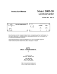
Model 2009-138
Instruction Manual
Downconverter
September 2015, Rev. D
2009 TEST DOWNCONVERTER
RF IN
CROSS TECHNOLOGIES, INC.
DC ALARM
J1
CROSS TECHNOLOGIES, INC.
DC POWER
IF OUT
•
•
J3
J2
Data, drawings, and other material contained herein are proprietary to Cross Technologies, Inc.,
but may be reproduced or duplicated without the prior permission of Cross Technologies, Inc.
for purposes of operating the equipment.
When ordering parts from Cross Technologies, Inc., be sure to include the equipment
model number, equipment serial number, and a description of the part.
CROSS TECHNOLOGIES, INC.
6170 Shiloh Road
Alpharetta, Georgia 30005
(770) 886-8005
FAX (770) 886-7964
Toll Free 888-900-5588
WEB www.crosstechnologies.com
E-MAIL [email protected]
INSTRUCTION MANUAL
MODEL 2009-138 Downconverter
TABLE OF CONTENTS
Warranty
1.0 General
1.1 Equipment Description
1.2 Technical Characteristics
2.0 Installation
2.1 Mechanical
2.2 Front Panel Indicators
2.3 Rear Panel Inputs and Outputs
2.4 Accessing the PC Card
2.5 Installation/Operation
3.0 Environmental Use Information
PAGE
2
3
3
4
5
5
5
6
6
6
7
WARRANTY - The following warranty applies to all Cross Technologies, Inc. products.
All Cross Technologies, Inc. products are warranted against defective materials and
workmanship for a period of one year after shipment to customer. Cross Technologies, Inc.’s
obligation under this warranty is limited to repairing or, at Cross Technologies, Inc.’s option,
replacing parts, subassemblies, or entire assemblies. Cross Technologies, Inc. shall not be
liable for any special, indirect, or consequential damages. This warranty does not cover parts
or equipment which have been subject to misuse, negligence, or accident by the customer
during use. All shipping costs for warranty repairs will be prepaid by the customer. There
are not other warranties, express or implied, except as stated herein.
CROSS TECHNOLOGIES, INC.
6170 Shiloh Road
Alpharetta, Georgia 30005
(770) 886-8005
FAX (770) 886-7964
Toll Free 888-900-5588
WEB www.crosstechnologies.com
E-MAIL [email protected]
2009-138 Manual, Rev. D
Page 2
09/22/15
Model 2009-138 Downconverter
1.0 General
1.1 Equipment Description
The 2009-138 Test Downconverter converts a 13.75 - 14.5 GHz signal to 950 - 1700 MHz with a low side local
oscillator (LO) (non-inverted spectrum). Featuring low phase noise and high stability, this unit is used to down
convert “clean” (having only this frequency) 13.75 - 14.5 GHz signals to 950 - 1700 MHz for test purposes. The
13.75 - 14.5 GHz input is mixed with a synthesized local oscillator (LO) signal to 950 - 1700 MHz. The mixer
output is applied to the output amplifier providing a nominal gain of +25 dB. Connectors are 75Ω type-F
(female) for the 950 - 1700 MHz output and 50Ω type-N (female) for the RF input. Front panel LEDs light
when DC power is applied (green) and when a PLL alarm occurs (red). DC power is provided by the LNB
voltage from the receiver under test or by an external wall mount power supply (option -P or -P4). The 2009
can be mounted on an 1 3/4” X 19” rack mount panel (option -R).
CROSS TECHNOLOGIES, INC.
RF IN
2009 TEST DOWNCONVERTER
CROSS TECHNOLOGIES, INC.
J1
DC ALARM
FIGURE 1.1
13.75
to
14.5
GHz
IN
DC POWER
IF OUT
•
•
J3
J2
Front and Rear Panels
2 GHz
LP
isolator
12.80 GHz
950
to
1700
MHz
OUT
PLL
2009-138 Block Diagram
FIGURE 1.2
2009-138 Manual, Rev. D
Block Diagram
Page 3
09/22/15
1.2 Technical Characteristics
TABLE 1.1
2009-138 Downconverter Specifications*
Input Characteristics
Input Impedance/Return Loss
Frequency
Level
Output Characteristics
50Ω/12 dB
13.75 - 14.5 GHz
-50 to -35 dBm
Impedance/Return Loss
75Ω / 10 dB
Frequency
950 to 1700 MHz
Level
-25 to -10 dBm
Output 1 dB Compression
0 dBm
Channel Characteristics
Gain at Band Center
+25 dB ±3 dB
Spurious Response
< -40 dBC, 950 - 1700 MHz out
Spectrum Sense
Non-inverting
Frequency Response
Synthesizer Characteristics
± 2 dB, 950 - 1700 MHz; ± 0.5 dB, any 10 MHz increment
Lo Frequency
12.80 GHz
Frequency Accuracy
± 2.5 ppm maximum
Phase Noise @ Frequency
dBC/Hz
100 MHz
1kHz
10kHz
100kHz
1MHz
-60
-75
-85
-100
-110
Indicators
DC Power
Green LED
Alarm
Red LED
Other
RF In Connector
Type-N (female), 50Ω
L-Band (IF) Out Connector
Type-F (female)
Size, Bench Top
4.7” wide x 1.75” high x 6.5” deep
Size, Rack Mount (-R)
19” Standard Chassis, 1.75” high x 7.0” deep (optional)
Power
+15 to +18 VDC, 250 ma on RF Out (wall mount power supply unit optional)
Available Options
-M
Type N RF (input), 50Ω BNC L-Band (output)
-P
120 VAC Wall Power Supply, +15 VDC
-P4
100-240 ± 10% VAC Wall Power Supply, +15 VDC
-R
1 RU Rack Mounting
-C
Power Supply not included. Requires Cross 2000-01 Power Supply
-W42
Alarm Control Treminal Strip, Dry Contact, NC-C-NO Terminations
*+10˚C to +40˚C; 2000 meters max elevation; 80% maximum humidity; Specifications subject to change without notice.
2009-138 Manual, Rev. D
Page 4
09/22/15
2.0 Installation
2.1 Mechanical
The 2009-138 is packaged in an aluminum extrusion. The -R option is mounted on a 1 3/4” X 19” panel that
can be mounted to a rack using the 4 holes at the ends (See Figure 2.1).
2.1.1 Cleaning Instructions
Wipe the exterior with a dry, soft cloth. Use no detergent or cleaning chemicals.
REAR SCREWS (4EA)
REAR PANEL
EXTRUSION
FRONT PANEL
CROSS TECHNOLOGIES, INC.
2009 TEST DOWNCONVERTER
DC ALARM
RACK MOUNT PANEL (FOR -R MODELS ONLY)
FRONT SCREWS (4EA)
FIGURE 2.1
Model 2009-138 Assembly (-R option shown)
2.2 Indicators
Figure 2.2 shows front panel indicators.
2009 TEST DOWNCONVERTER
CROSS TECHNOLOGIES, INC.
DC ALARM
DS1 - DC POWER LED
Lights green when DC
power is present.
FIGURE 2.2
2009-138 Manual, Rev. D
DS2 - ALARM LED
Lights red when PLL
comes out of lock.
Model 2009-138 Front Panel Indicators
Page 5
09/22/15
2.3 Input / Output Signals
Figure 2.3 shows the input and output signals to the 2009-138.
GND
J1 - RF IN
13.75 to 14.5 GHz input .
This must be a “clean” input with
no image or other frequency
present. The max. input level is
-35dBm. This is a 50Ω, Type N,
female connector.
+15
J3 - DC POWER
The +15 VDC unregulated DC voltage from the
wall power supply. (Option -P models ONLY.)
CROSS TECHNOLOGIES, INC.
RF IN
DC
POWER
J1
FIGURE 2.3
J3
RF OUT
J2 - IF OUT
The 950 to 1700 MHz
output at -10dBm max
level with -35dBm in.
This is a 75Ω, Type F,
female connector. May
also contain +15 to +18
VDC, 250ma from LNB.
J2
Model 2009-138 Rear Panel Inputs and Outputs
2.4 Accessing the PC Card
There are NO USER JUMPERS or other on-card controls. ALTHOUGH IT IS NOT RECOMMENDED AND
MAY VOID THE WARRANTY the following shows how to remove the printed circuit board (PCB) from the
extrusion:
1. Always remove power when installing or removing the PCB from the extrusion
2. Remove four (4) rear panel screws (see Figure 2.1).
3. Gently pull the rear panel and PCB assembly completely out of the extrusion.
4. To install the PCB, gently push the rear panel and PCB assembly completely into the extrusion
(make sure the shield goes in the lower channel and the PCB in the next channel above that) and
that the front panel indicators line up with the front panel holes.
5. Install four (4) rear panel screws.
2.5 Installation / Operation
2.5.1 Installing and Operating the 2009-138
1. For -P models, connect one end of the Wall Power Supply to the 2009-138 DC Power In, J3,
and the other end to 115 VAC, 60 Hz (Figure 2.3).
2. Connect a -35 dBm, maximum signal to RF IN, J1 (Figure 2.3).
3. Connect the IF OUT, J2, to the receiver under test (For models powered from the LNB be sure
that the LNB voltage is +15 to +18 VDC, 250 mA max.) (Figure 2.3).
4. Be sure DS1 (green, DC Power) is on and DS2 (red, Alarm) is off (Figure 2.2).
2009-138 Manual, Rev. D
Page 6
09/22/15
2.5.2 Option W42, Alarm Outputs
This Option, W42, provides an alarm terminal strip on the rear of the unit,
with the following three terminals:
NO = Normally Open (Open when there is no alarm condition.)
NC = Normally Closed (Closed when there is no alarm condition.)
C = Common
The alarm outputs function as described below:
(Normal Operation)
Power ON or
NO is Opened (not connected to C)
PLL Locked
NC is Closed (connected to C)
NC C NO
Alarm Contact Terminal Strip
Push to release wire
20 - 24 AWG
(Alarmed Condition)
Power OFF or
NO is Closed (connected to C)
PLL Alarmed
NC is Opened (not connected to C)
3.0
Environmental Use Information
A.
Rack-Mounting - To mount this equipment in a rack, please refer to the installation instructions
located in the user manual furnished by the manufacturer of your equipment rack.
Mechanical loading - Mounting of equipment in a rack should be such that a hazardous condition
does not exist due to uneven weight distribution.
Elevated operating ambient temperature - If installed in a closed or multi-unit rack assembly,
the operating ambient temperature of the rack may be greater than room ambient temperature.
Therefore, consideration should be given to Tmra.
Reduced air flow - Installation of the equipment in a rack should be such that the amount of air flow
required for safe operation of the equipment is not compromised. Additional space between unit
may be required.
Circuit Overloading - Consideration should be given to the connection of the equipment to the supply
circuit and the effect that overloading of circuits could have on over current protection and supply wiring.
Appropriate consideration of equipment name plate rating should be used, when addressing this concern.
Reliable Earthing - Reliable earthing of rack-mounted equipment should be maintained. Particular
attention should be given to supply connections other than direct connection to the Branch
(use of power strips).
Top Cover - There are no serviceable parts inside the product so, the Top Cover should not be removed.
If the Top Cover is removed the ground strap and associated screw MUST BE REINSTALLED
prior to Top Cover screw replacement. FAILURE TO DO this may cause INGRESS and/or EGRESS
emission problems.
B.
C.
D.
E.
F.
G.
2009-138 Manual, Rev. D
Page 7
09/22/15
CROSS TECHNOLOGIES, INC.
6170 Shiloh Road
Alpharetta, Georgia 30005
(770) 886-8005
FAX (770) 886-7964
Toll Free 888-900-5588
WEB www.crosstechnologies.com
E-MAIL [email protected]
Printed in USA
2009-138 Manual, Rev. D
Page 8
09/22/15