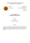
1
digital optical links (1 per FEB electronics drawer) which the ROD should be able to
manage and process at a maximum level 1 trigger rate of 100 kHz. This data is then sent
to the ROS which is the next step in the ATLAS DAQ chain.
Reference [4] shows a detailed explanation of the low- level library used to access
and configure the ROD motherboard. This library is integrated in the TileVmeROD
package.
A view of the panels of the ROD Final menu is shown in Figure 8. In order to
access the ROD module, the user has to specify the slot number in the crate where the
card is placed and the type of crate controller to use (VP110 or BIT3). With the Access
Hardware button, the ROD is initialized and all registers of the different FPGA blocks
can then be accessed. There are specific buttons to read all the registers in the menu
(Read All Registers) and to write them (Write All Registers). From the ROD Final menu
the user may access to the different FPGA blocks of the ROD from a notebook subpanel.
Figure 8: XTestROD ROD Final VME Controller menu.
From the Processing Units Booting box panel the user can boot the PUs in the
ROD. From PU 1 up to PU 4 option menus the user selects the PU type placed in the
corresponding MB slot. The possible choices are Dummy PU (see Section 4.3.6), DSP
PU (see Section4.3.7) and Empty (no PU plugged). With the File selection entry buttons
the user selects the online software code files to load into the DSP PU Input FPGA
(InFPGA File button) and into the DSP (DSP File button). No code needs to be provided
for the dummy PU as no booting is needed for this device.
13