1
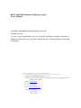
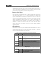
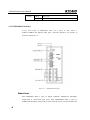
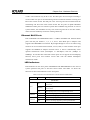
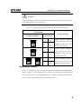
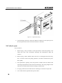
KIEN 1000/2000 Industrial Ethernet Switch
User’s Manual
Beijing KYLAND Technology Co., Ltd.
KIEN 1000/2000 Industrial Ethernet Switch
User’s Manual
Copyright © 2005-2009 KYLAND Technology CO., LTD.
All rights reserved.
No part of this documentation may be excerpted, reproduced, translated, annotated or
duplicated, in any form or by any means without the prior written permission of KYLAND
Corporation.
Publisher: Beijing KYLAND Technology Co., Ltd.
Address: Chongxin Creative Building, Shixing East Street 18#, Shijingshan District,
Beijing, China (100089)
Website: www.kyland.cn
Tel: +86 –10-88798888
Fax: +86 –10-88796678
E-mail: [email protected]
Version: V1, Sep, 2005
V2, Dec, 2008
V3, Apr, 2009
Preface
The KIEN1000 and KIEN2000 are high-performance industrial Ethernet switches
designed and developed by KYLAND for industrial applications. The KIEN1000 and
KIEN2000 may operate in harsh industrial environments because they employ
high-performance switch engines, solid, fan less and ribbed case with efficient heat
dissipation surface, protections against over current and overvoltage of power input,
EMC protections, and excellent protection performance of RJ45 ports. The redundant
network and power supply ensures more reliability for the system operation.
This document contains the installation instructions of the KIEN1000 and KIEN2000
for the users’ reference.
Chapter One: Hardware Structure of KIEN1000 & KIEN2000 Series
Chapter Two: Installation of KIEN1000 & KIEN2000 Series
All product specifications are subject to change without notice. Please
visit our website or contact our sales representative directly to have the
update details.
Safety Notices
These products have good and reliable performance in designed use range. But
man-made damages to the switch shall be avoided.
z
Read this Manual thoroughly and keep it well for future reference.
z
Do not place the switch at where is close to water source or dampness.
z
Place power cables at where cannot be touched and do not place any stuff on
power cables.
z
Do not tie or wrap power cables to prevent fire.
z
Fasten power connectors and connectors of other units tightly and check them
often.
In the following cases, please power off immediately and contact us.
1.
water into the switch;
2.
the switch is damaged due to falling or cases are broken;
3.
the switch has abnormal operations or its performance completely changes;
4.
The switch gives off odor, smoke or noise.
z
Please keep the switch clean. If necessary, wipe it with soft cotton cloth.
z
Do not repair it by yourself except for clear instruction in this Manual.
Warning Marks:
This Manual uses following two kinds of conspicuous warning marks to remind
users in operating:
Warning: please give enough attention to the remarks following the mark.
Inappropriate operations may cause severe damages to the switch and
operators.
Attention: pay attention to the remarks following the mark.
Table of Contents
Chapter One: Hardware Structure.............................................................................................................. 1
1.1 System Structure.................................................................................................................................. 1
1.2 Switch Structure................................................................................................................................... 2
1.2.1 Casing ........................................................................................................................................ 2
1.2.2 KIEN1000 Front Panel .............................................................................................................. 2
1.2.3 KIEN2000 Front Panel .............................................................................................................. 4
1.2.4 Top Panel ................................................................................................................................... 6
Chapter Two: Installation .......................................................................................................................... 11
2.1 Mounting Requirements .................................................................................................................... 11
2.2 Install Switch ..................................................................................................................................... 11
2.2.1 DIN Rail Mounting.................................................................................................................. 11
2.2.2 Wall Mounting ......................................................................................................................... 13
2.3 Cable Wiring...................................................................................................................................... 16
2.4 Optical Fiber Wiring .......................................................................................................................... 17
2.5 Cables Layout .................................................................................................................................... 18
Chapter One: Hardware Structure
1.1 System Structure
The hardware structure of KIEN1000 and KIEN2000 is showed in the Figure 3-1.
Figure 1-1
Hardware Structure
The hardware system mainly consists of the following parts:
1. The switching network controller employs the high-performance ASIC chip
technique and provides second-layer wire rate forward of data packages.
2. Fiber ports adopt integrated fiber optic transceiving modules and have stable
performance.
3. The power adopts the industrial power and offers over current, overvoltage and
EMC protections.
4. All Ethernet ports have EMC protections.
1
KIEN1000/2000 User’s Manual
1.2 Switch Structure
1.2.1 Casing
Warning: The case is a part of the heat dissipation system, do not touch the
case when the switch operates to avoid heat burn.
1.2.2 KIEN1000 Front Panel
In the front panel of KIEN1000, there are 2 uplink (redundant) 10Base-T/100Base-TX
Ethernet RJ45 ports, 6 10Base-T/100Base-TX Ethernet RJ45 ports, and LED indicators.
Its structure is showed in the Figure 1-2.
Fig 1-2 KIEN1000 Front Panel
Uplink (Redundant) Ethernet RJ45 Ports
Each KIEN1000 has 2 uplink redundant 10Base-T/100Base-TX RJ45 ports. Each
KIEN1000B has 2 uplink 10Base-T/100Base-TX RJ45 ports. The port numbers are 4
and 8. Each port is adaptive and supports auto MDI/MDI-X connection. Two uplink
2
Chapter One: Hardware Structure
redundant Ethernet RJ45 ports can form the twisted-pair redundant ring network, in
case of system failures, the redundant recovery time of the ring network is less than
100ms, which increases reliability of network running effectively.
Ethernet RJ45 Ports
Each KIEN1000 and KIEN1000B offers 6 10Base-T/100Base-TX Ethernet RJ45
ports with the port number 1, 2, 3, 5, 6, and 7. Each RJ45 port is adaptive and
supports auto MDI/MDI-X connection. By straight-through or cross-over cable wiring,
switches can be connected with terminals, servers, hubs, or other switches. Each port
supports the IEEE802.3x adaptive function and it is able to automatically select
optimal transmission mode (half-duplex or full-duplex) and rate (10Mbps or
100Mbps). If switches that connected to these ports do not support the adaptive
function, these ports will transmit correct data with the default half-duplex
transmission mode.
LED Indicators
LED Indicators on the front panel of KIEN1000 and KIEN1000B show the state of
system operation and ports to find and correct faults. The Table 1-1 shows the
functions of these LED indicators on the front panel.
Table 1-1 Functions of LED Indicators on the Front Panel of KIEN1000
LED
State
Descriptions
System State
On
RUN
POWER1
POWER2
Blinking
The uplink ports are set as redundant mode and the switch is
set as local.
The uplink ports are set as redundant mode and the switch is
set as remote.
Off
The uplink ports are set as straight-through mode
On
Power is being supplied to power input POWER1
Off
Power is not being supplied to power input POWER1
On
Power is being supplied to power input POWER2
Off
Power is not being supplied to power input POWER2
RJ45 Ports State
Each RJ45 port has two indicators: the yellow is the indicator for port rate and the green is
port link state.
10M/100M
On
Data is being transmitted at 100Mbps
(Yellow)
Off
Data is being transmitted at 10Mbps
LINK/ACT
On
Active link established
3
KIEN1000/2000 User’s Manual
(Green)
Blinking
Active link
Off
No active link
1.2.3 KIEN2000 Front Panel
In the front panel of KIEN2000, there are 2 pairs of fiber ports, 6
10Base-T/100Base-TX Ethernet RJ45 ports, and LED indicators. Its structure is
showed in the Figure 1-3.
Figure 1-3
KIEN2000 Front Panel
Fiber Ports
Each KIEN2000 offers 2 pairs of uplink redundant 100Base-FX full-duplex
single-mode or multi-mode fiber ports. Each KIEN2000B offers 2 pairs of
100Base-FX full-duplex single-mode or multi-mode fiber ports. The port numbers are
4
Chapter One: Hardware Structure
4 and 8. The connector may be SC or FC. The fiber ports are used in pair including a
TX and a RX. TX port is the transmitting end and connected with the receiving end
RX of the remote switch. The RX port is the receiving end and connected with the
transmitting end TX of the same remote switch. The two pairs of uplink redundant
100Base-FX fiber ports can form the optical fiber redundant ring network. In case of
system failures, the redundant recovery time of the ring network is less than 100ms,
which increases reliability of network running effectively.
Ethernet RJ45 Ports
Each KIEN2000 and KIEN2000B offers 6 10Base-T/100Base-TX Ethernet RJ45
ports with the port number 1, 2, 3, 5, 6, and 7. Each RJ45 port is adaptive and
supports auto MDI/MDI-X connection. By straight-through or cross-over cable wiring,
switches can be connected with terminals, servers, hubs, or other switches. Each port
supports the IEEE802.3x adaptive function and it is able to automatically select
optimal transmission mode (half-duplex or full-duplex) and rate (10Mbps or
100Mbps). If switches that connected to these ports do not support the self-adapting
function, these ports will transmit correct data with the default half-duplex
transmission mode.
LED Indicators
LED Indicators on the front panel of KIEN2000 and KIEN2000B show the state of
system operation and ports to find and correct faults. The Table 1-2 shows the
functions of these LED indicators on the front panel.
Table1-2 Functions of LED Indicators on the Front Panel of KIEN2000
LED
State
Descriptions
System State
On
RUN
POWER1
POWER2
Blinking
The uplink ports are set as redundant mode and the switch is
set as local.
The uplink ports are set as redundant mode and the switch is
set as remote.
Off
The uplink ports are set as straight-through mode
On
Power is being supplied to power input POWER1
Off
Power is not being supplied to power input POWER1
On
Power is being supplied to power input POWER2
Off
Power is not being supplied to power input POWER2
RJ45 Ports State
5
KIEN1000/2000 User’s Manual
Each RJ45 port has two indicators: the yellow is the indicator for port rate and the green is
port link state.
10M/100M
On
Data is being transmitted at 100Mbps
(Yellow)
Off
Data is being transmitted at 10Mbps
LINK/ACT
(Green)
On
Active link established
Blinking
Active link
Off
No active link
Fiber Ports State (4, 8)
LINK/ACT
On
Active link established
Blinking
Active link
Off
No active link
1.2.4 Top Panel
On the top panel of KIEN1000 and KIEN2000, there are two power input terminal
blocks, alarm relay output and DIP switches.
Figure 1-4
Top Panel
Power Input Terminals
KIEN1000 and KIEN2000 have redundant power input function. P1 and P2 are two
power input terminals. Any one of them can be used independently. Or, they can be
6
Chapter One: Hardware Structure
connected with two sets of external independent DC power systems. In case of failure,
the switch is able to run normally, improving reliability of network running. 3-pin
terminals with the space of3.81 mm are used to connect powers and the diameter of
power cables is less than 1.5mm.
Wiring is shown in the Figure 1-5. Connection and mounting steps are as follows:
1. Peel off the outer skin of a length of 5mm of the power cable and twist the
copper wires together;
2. Screw on the “locking screws for power cables” with a 2.5mm one-slot
screwdriver. Insert the power cable into holes at the tail of the terminal and
screw down the “locking screws for power cables”.
3. Plug the power terminal into the DC socket of the switch. Screw down two
“terminal locking screws” with s 2.5mm one-slot screwdriver to make the
terminal connect with the power connector tightly.
Figure 1-5 Wiring of the DC Power Terminal
Alarm Relay Output
This terminal is a group of normally-open contacts and its appearance is identical
to the power input terminal. Under the normal status, there is no warning and this
terminal is in open status. In case of failures of any one power, the terminal is
closed. It can be connected with other switching value acquisition devices or
warning lights and warning buzzers, to remind operators in time. The maximum
voltage of this terminal is DC30V and its maximum input power is 24VA. The
Figure 1-6 is the schematic when the switch connects with an external warning
indicator. The wiring of other applications is similar with this
7
KIEN1000/2000 User’s Manual
Attention:
KIEN1000 and KIEN2000 have the warning output function but KIEN1000B and
KIEN2000B have no such a function.
The wiring and mounting steps are same as those of the power terminal.
Figure 1-6
Alarm Lamp and relay output
DIP Switch
The property setting switch is used to set the redundant mode and common direct link of
2 uplink redundant electric ports or fiber ports, and local and remote property of the
redundant mode. Hence, this switch is effective only for KIEN1000 and KIEN2000 and
is not effective for KIEN1000B and KIEN2000B. The switch has two positions that are
defined T and F respectively. T is used to set the redundant mode and common direct
link of 2 uplink redundant Ethernet ports or fiber ports. When T is ON, the two uplink
electric ports are set as common direct link mode, contrarily the common direct link
mode. F is used to set local and remote property of the redundant mode when the uplink
electric port or fiber ports are in redundant mode. When T is OFF and F is ON, the
switch is local, contrarily remote. The relationship between the specific positions of the
switch and its properties is listed in the Table 3-3.
8
Chapter One: Hardware Structure
Attention:
In the twisted-pair or optical fiber redundant ring network, only one switch can be set
as the local and others are set as remote.
Table1-3 Corresponding Relationship between Positions and Attributes of the Switch
Switch Position
Attribute Meaning
Position Schematic
T
1 2
ON
Logic Position
F
T
OFF
Uplink redundant Ethernet
ports or fiber ports are the
F
OFF
redundant mode and the
switch is set as remote.
T
1 2
ON
F
T
OFF
Uplink redundant Ethernet
ports or fiber ports are the
F
ON
redundant mode and the
switch is set as local.
T
1 2
ON
FT
1 2
ON
F
T
ON
Uplink redundant Ethernet
ports or fiber ports are the
F
ON/OFF
common direct link mode.
Grounding Terminal
There is a grounding screw hole at the bottom panel of KIEN1000 and KIEN2000. As
shown in Figure 1-7, the grounding wire is connected to cold pressed terminal, both of
them are fixed in the hole with grounding screw. The other end of grounding wire can
be to the earth. The grounding wire is no less than 2.5mm.
9
KIEN1000/2000 User’s Manual
Figure 1-7
10
KIEN1000 and KIEN2000 Grounding Methods
Chapter Two: Installation
2.1 Mounting Requirements
The switch is single-body structure and can be directed locked on the standard 35mm
DIN rail or is mounted on vertical walls or internal walls of the switch cabinet with the
wall mounting part.
Before mounting the switch, make sure of appropriate operating environment,
including correct power requirements, enough space, and suitable distance to the
networking units. Please also confirm the following mounting requirements:
1. Power: standard products of KIEN1000 and KIEN2000 serial industrial switches
use the redundant 24V (18VDC~36VDC) DC power.
2. Environment temperature: -40℃~75℃
3. Grounding resistance: <5Ω
4. Check whether uplink twisted-pair wires or optical fibers are laid in place in
accordance with configuration requirements under the contract.
5. Avoid direct sunshine and keep it away from heating sources or areas where have
strong electromagnetic interference.
6. Standard products of KIEN1000 and KIEN2000 serial industrial Ethernet
switches only provide DIN rail mounting parts. Users need to prepare DIN rails.
But if the wall mounting is required, users need to purchase the wall mounting
part additionally. Users must prepare screws, nuts and tools required by the wall
mounting to ensure reliable mounting.
7. Check existence of cables and connectors required by mounting.
2.2 Install Switch
2.2.1 DIN Rail Mounting
The standard 35mm DIN rail-type mounting provides most industrial applications
with convenient mounting. When you take out the switch from the packing box, you
will find that the green plastic DIN rail-connecting position has already been fixed on
the rear panel of KIEN1000 or KIEN2000. The Figure 4-1 shows the size of rail-type
KIEN1000/2000 User’s Manual
mounting. If you want to mount KIEN1000 or KIEN2000 on the DIN rail, please
check mounting of the DIN rail prior to mounting of the switch. The check shall
mainly focus on two items below:
1. Ensure the DIN rail is fixed solidly, other units are not on it, and enough space
is reserved for mounting the switch.
2. On the DIN rail, make sure there is power input that is suitable for operating of
KIEN1000 or KIEN2000.
Figure2-1 Size of Rail-Type Mounting for KIEN1000 and KIEN2000
After choosing the mounting position of the switch, mount it on the DIN rail according
to following steps:
12
Chapter Two: Installation
a
b
Figure 2-2 Mount KIEN1000/KIEN2000 on the DIN Rail
1. As shown in the Figure 2-2a, insert the lower part of the DIN rail into the fixing
slot with spring support under the rail connecting seat. Push the bottom panel of
the switch upward slightly and turn it.
2. As shown in the Figure 4-2b, lock the DIN rail Into the DIN rail connecting
position and confirm reliable mounting on the DIN rail of the switch.
2.2.2 Wall Mounting
In the situation that DIN rail-type mounting is inconvenient, it is better to adopt wall
mounting. KYLAND provides users with wall mounting boards that are mounting parts
for mounting of KIEN1000 and KIEN2000. The size of wall mounting is shown in the
Figure2-3.
13
KIEN1000/2000 User’s Manual
Figure 2-3
KIEN1000, KIEN2000 Wall Mounting
Attention:
The wall mounting plate is not contained in the standard accessories of KIEN1000 and
KIEN2000. If you need it, please order it additionally when you order the switch.
The steps of wall mounting of KIEN1000 and KIEN2000 are as follows:
1. Remove the DIN Rail kit from the switch
2. Take out the wall mounting board and its mounting screws (M3×6 cross
recessed countersunk flat head screws) from the packing box. Mount the board on
the position where the DIN rail kit is. Ensure the mounting direction of the plate
is as shown in the Figure 2-4.
14
Chapter Two: Installation
Figure 2-4 Install Wall Mounting Plate
3. Select a vertical wall or internal wall of the switch cabinet as the mounting
position. If the vertical wall is selected, it is recommended to mount the switch
with Ф6 plastic expansion bolts and Ф3 taping screws. According to the
mounting size in the Figure 2-3, drill 4 Ф6 holes on the wall with a impact
electric drill with a depth that can completely contains the Ф6 plastic expansion
bolts. Insert the plastic expansion bolts into holes on the wall and screw the
tapping screws into the plastic expansion bolts with a cross head screwdriver. But
do not screw them tightly and keep a space of about 5mm. If the internal wall of
the switch cabinet is selected, recommend to open 4 M3 screw holes when the
switch cabinet is manufactured in accordance with the mounting size in the
Figure 2-3. Or drill 4Ф4 holes with a electric portable drill on site. Screw four
M3×10 cross recessed pan head screws into 4 holes. If the holes have no threads,
mount four M3 nuts on its back. At last, do not completely screw down screws
and keep a space of 5mm.
15
KIEN1000/2000 User’s Manual
4. After screws are fixed on the wall, mount the switch on the selected position and
make 4 screws pass through 4Ф6.5 holes on the wall hanging plate. Slide down
the switch, as showed in the Figure 2-5. Screw down 4 screws to fasten the switch
on the wall or the internal wall of the switch cabinet.
Figure 2-5
Wall Mount
2.3 Cable Wiring
After KIEN1000 or KIEN2000 is mounted properly, cable can be wired, which mainly
include cable connection of the following ports:
1. Service Ports
KIEN1000 and KIEN2000 provide 10Base-T/100Base-TX Ethernet RJ45 ports
that are connected with terminals with straight-through cables and with
networking units with cross-over cables.
2. Power Supply Input
KIEN1000 and KIEN2000 use the 24V DC powers. After other cables are
connected, power cable can be connected.
16
Chapter Two: Installation
2.4 Optical Fiber Wiring
Each KIEN2000 provides 2 pairs of uplink redundant 100Base-FX full-duplex
single-mode or multi-mode fiber ports that can build the optical fiber redundant ring
network. In case of failures of units or optical fibers in the network, the network
recovers communication within 300ms. Each KIEN2000B provides 2 pairs of uplink
100Base-FX full-duplex single-mode or multi-mode fiber ports that can build the
optical fiber chain network. Fiber ports may adopt SC or FC according to requirements.
Attention:
The switch use laser to transmit signal in optical fibers. The laser is in accordance with
requirements for the Class 1 laser products. In normal operation, it is harmless to eyes.
But when units are connected with powers, do not directly watch optical transmitting
ports and the end surface of optical fiber terminators.
Connection steps of pluggable optical fiber modules are showed as follows:
1. Remove and keep rubber cases in SC or FC ports. When it is not working, mount
the rubber cases to protect optical fiber terminators.
2. Check cleanness of optical fiber terminators. Wet clean paper towel or tampon
slightly and clean plugs of optical fibers softly. Dirty optical fiber terminators
will reduce optical transmission quality and affect port performance.
3. Connect one side of the optical fiber with an optical port of the switch and
connect the other side with an optical port of another unit, as showed in the
Figure 2-6.n
17
KIEN1000/2000 User’s Manual
Figure 2-6
Optical Fiber Wiring
4. Upon finishing connection, check the LIK/ACT indicator for the optical port on
the front panel of the switch. On means effective connection.
2.5 Cables Layout
Wire as follows:
1. Before laying, verify accordance of the specification, model and quantity of all
cables and wires with construction drawings and requirements under the
contract.
2. Before laying, check whether cables and wires are damaged and ensure they
have ex-works records and quality guarantee, and other certificates that prove
their quality.
3. The specification, quantity, route, and position of cables and wires shall accord
with design requirements under construction drawings. The laying length of each
cable and wire shall be determined according to real position.
4. In laying, cables and wires shall not have breaking or connectors except ends.
5. User cables shall be separated from power cables.
18
Chapter Two: Installation
6. In walkways, cables and wires shall be laid straightly and tidily and they shall
have even, smooth and straight bends.
7. In wire case, they shall be straight without overreaching casings to block holes of
other cables. At exits or bends of casings, cables shall be bundled and fastened.
8. When cables, power cables and grounding wires are in one case, they shall not
overlap. If they are too long, they shall be tidily coiled and placed in the middle
of chutes and they shall not be placed on other cables and wires.
9. When the tail fiber is laid, ties of optical fibers shall be prevented. Bends shall be
reduced to the minimum extent and their bending radius shall not be too little.
Bundling shall be appropriate and shall not be too tight. When placed on chutes,
they shall be separated from others.
10. Two sides of cables and wires shall have marks with simple and clear
identification to facilitate maintenance.
Attention:
When the tail fiber is laid, ties of optical fibers shall be prevented. Undersize radius
will cause great loss of optical sign in link and affect communication quality.
19