1
PSI System Controls and Diagnostics
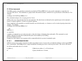
9.3.2 Signal cables
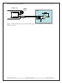
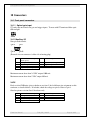
Good-quality screened four-core cable should be used, terminated in a type 0B four-pin on Lemo
plug at the F100 end. If you are measuring currents at the bottom end of the dynamic range, then
we recommend using low-noise anti-triboelectric cable.
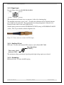
The connection at the sensor end can be varied according to your needs – it may be a coaxial
connector, or simply ring lugs for direct attachment to convenient points. The minimum
requirement is to connect the signal in (pin 1) and return (pin 2) lines. If you want to use the
input summing or calibration current loopback features, you should also connect pin 3 to the
sensor appropriately. The fourth core is F100 chassis potential. Normally this is left
unconnected at the sensor end, but in some situations you may get better noise performance if it
is connected to a ground screen at the sensor end also.
9.3.3 Signal current path
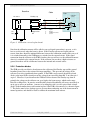
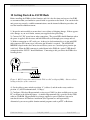
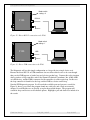
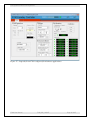
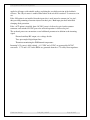
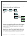
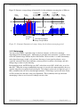
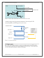
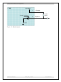
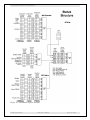
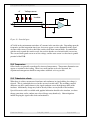
Figure 4 illustrates how the current you are measuring passes along the signal conductor to the
F100 input, taking the example of a beamline with a positive ion source and a Faraday cup. The
situation with electrons or negative ions is analogous, but with reversed direction of conventional
current. The F100 can measure conventional current flowing into or out of its input. It is
important that the current return circuit is continuous, or you will not measure correctly or even
at all, despite a beam arriving at the collector.
Beamline
Ion source
Cable
F100
Faraday cup
4
M+
3
e-
1
2
HV
PSU
Suppression
HV
1
2
3
4
Signal
Return
Screen
Figure 4. Path of measured current when measuring the current of a positive ion beam
A current of positive ions is extracted from an ion source by the potential of a high voltage power
supply. A corresponding current must flow from the supply. The ions are collected by the
Faraday cup. Secondary electrons released from the surface of the cup are prevented from
escaping (and thus rendering the monitored current inaccurate) by the suppression fields, which
can be electrostatic, magnetic, or a combination of both.
F100 User Manual
F100_UM_140307
Page 21 of 95