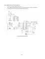
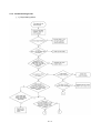
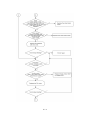
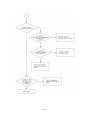
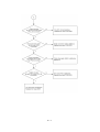
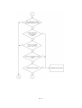
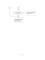
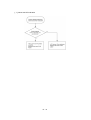
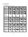
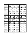
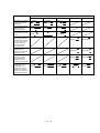
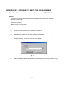
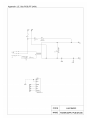
1
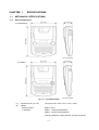
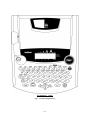
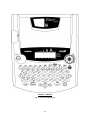
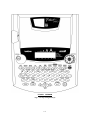
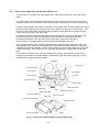
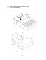
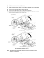
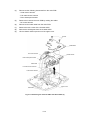
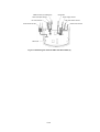
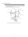
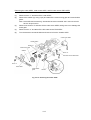
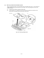
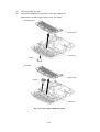
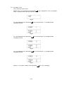
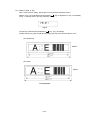
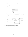
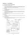
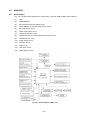
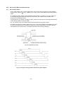
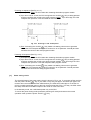
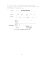
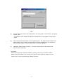
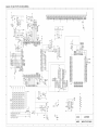
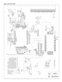
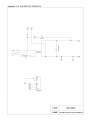
SERVICE MANUAL
MODEL: PT-2300/2310/2450
SERVICE MANUAL
MODEL: PT-2300/2310/2450
PREFACE
This publication is a service manual covering the specifications, theory of operation,
disassembly/reassembly procedure, and troubleshooting and error message of the Brother PT2300/2310/2450. It is intended for service personnel and other concerned persons to accurately
and quickly provide after-sale service for our PT-2300/2310/2450.
To perform appropriate maintenance so that the machine is always in best condition for the
customer, the service personnel must adequately understand and apply this manual.
This manual is made up of four chapters and appendices.
CHAPTER I
SPECIFICATIONS
CHAPTER II
MECHANISMS
CHAPTER III
ELECTRONICS
CHAPTER IV
TROUBLESHOOTING AND ERROR MESSAGE
APPENDICES
1. SOFTWARE TO WRITE THE SERIAL NUMBER
2. CIRCUIT DIAGRAMS
© Copyright Brother 2001
All rights reserved.
No part of this publication may be reproduced in any
form or by any means without permission in writing
from the publisher.
Specifications are subject to change without notice.
CHAPTER I
SPECIFICATIONS
CONTENTS
CHAPTER I SPECIFICATIONS......................................................................... I-1
1.1
1.2
1.3
MECHANICAL SPECIFICATIONS ........................................................................ I-1
1.1.1
External Appearance ...................................................................................... I-1
1.1.2
Keyboard........................................................................................................ I-2
1.1.3
Display ........................................................................................................... I-2
1.1.4
Printing Mechanism........................................................................................ I-2
1.1.5
Tape Cassette ................................................................................................ I-3
1.1.6
Tape Cutter .................................................................................................... I-3
ELECTRONICS SPECIFICATIONS ...................................................................... I-9
1.2.1
Character Generator....................................................................................... I-9
1.2.2
Power Supply ................................................................................................. I-9
KEY COMMANDS FOR SPECIAL FUNCTIONS ................................................... I-9
1.3.1
Initializing ....................................................................................................... I-9
1.3.2
Demonstration Print........................................................................................ I-9
i
CHAPTER I
SPECIFICATIONS
1.1
MECHANICAL SPECIFICATIONS
1.1.1
External Appearance
(PT-2300/2310)
(PT-2450)
Fig. 1.1-1 PT-2300/2310/2450
(1)
Dimensions (W x D x H)
(2)
Weight
Machine proper
In package
194 x 242 x 65.5 mm (7.64" x 9.53" x 2.59")
Approx. 900 g
Approx. 1.6 kg (PT-2300/2450)
Approx. 2.9 kg (PT-2310/2450cc)
(including batteries, a tape cassette, and user's manual)
I-1
1.1.2
Keyboard
(1)
Entry system
Rubber key pad
(2)
Number of alphanumeric and symbol keys
39
(3)
Number of function keys
12 (including “On/Off (
(4)
Key arrangement
See Fig. 1.1-2.
(5)
Navigation dial (PT-2450)
Rotary switch : 20 positions / cycle
) ” key)
Set key : 1
1.1.3
1.1.4
Display
(1)
Display type
Liquid crystal display (LCD)
(2)
Display composition
16 x 59 dots
(3)
Number of indicators
20 (See Fig. 1.1-2.)
(4)
Dot size
0.65 mm(25.6mils) wide by 0.65 mm(25.6mils) high
(5)
Field-of-view angle adjustment
Fixed by a resistor
Printing Mechanism
(1)
Print method
Thermal transfer onto plastic tapes (laminate tape and
non-laminated tape) or special tapes (instant lettering tape,
non-laminated thermal film tape, iron-on transfer tape, and
porous-stamp tape)
(Fixed print head and tape feeding mechanism)
(2)
Print speed
(3)
Print head
10 mm/second (Typical)
Type
Thermal print head
Heat generator
Consists of 112 heating elements vertically aligned
(PT-2450 : 128 heating elements)
Size of heating element
(4)
0.195 mm (7.7 mils) wide by 0.141 mm (5.6 mils) high
Character size
Character size
Height x Width (dots)
Size 6
1.55 mm x 1.13 mm (11 x 8)
Size 9
1.97 mm x 1.41 mm (14 x 10)
Size 12
2.82 mm x 2.12 mm (20 x 15)
Size 18
4.51 mm x 3.38 mm (32 x 24)
Size 24
5.92 mm x 4.37 mm (42 x 31)
Big <12 mm>
7.61 mm x 5.64 mm (54x 40)
Size 36
9.02 mm x 6.77 mm (64 x 48)
Size 42 (PT-2300/2310)
10.72 mm x 8.04 mm (76 x 57)
Size 48 (PT-2450)
11.84 mm x 8.74 mm (84 x 62)
Big <18 mm> (PT-2300/2310)
13.54 mm x 10.30 mm (96 x 73)
Big <24 mm> (PT-2450)
16.07 mm x 11.99 mm (114 x 85)
* The height and width of the printed character are different depending on characters.
The values in the above list refer to the values of ‘H’ of HELSINKI.
* The character size indicates the point size.
I-2
1.1.5
Tape Cassette
(1)
Cassette
(2)
Types of tape cassettes
Cartridge type
• Laminated tape cassette
Laminate tape, ink ribbon, and adhesive base tape
• Non-laminated tape cassette
Non-laminate tape and ink ribbon
• Instant lettering tape cassette Instant lettering tape and ink ribbon
• Non-laminated thermal film
Non-laminated thermal film tape
tape cassette
• Iron-on transfer tape cassette Iron-on transfer tape and ink ribbon
(3)
• Stamp tape cassette
Porous-stamp tape and base paper
• Cloth tape cassette
Cloth tape and ink ribbon
Tape size
Width
Length
6, 9, 12, 18, 24
mm
8m
Non-laminate tape
6, 9, 12, 18, 24
mm
8m
Instant lettering tape
18 mm
8m
Non-laminate thermal film
tape
12, 18 mm
8m
Iron-on transfer tape
18 mm
6m
Porous-stamp tape
18, 24 mm
3m
Cloth tape
12 mm
4m
Laminate tape
(4)
(5 m for the fluorescent coating tape)
Tape cassette packed with the machine
Laminated tape cassette containing a 12-mm-wide black
ink ribbon, laminate tape, and adhesive base tape
1.1.6
Tape Cutter
(1)
Tape cutting
Automatic cutter (scissors type)
(2)
Cutter unit
Not user-replaceable
I-3
PT-2300/2310
U.S.A.
Fig. 1.1-2 Key Arrangement (1)
I-4
PT-2450
BELGIUM
Fig. 1.1-2 Key Arrangement (2)
I-5
PT-2450
FRENCH
Fig. 1.1-2 Key Arrangement (3)
I-6
PT-2450
GERMAN
Fig. 1.1-2 Key Arrangement (4)
I-7
PT-2450
U.K.
Fig. 1.1-2 Key Arrangement (5)
I-8
1.2
ELECTRONICS SPECIFICATIONS
1.2.1
Character Generator
(1)
(2)
Internal characters
Internal font
U.S.A. (PT-2300/2310)
179 characters
U.K./ FRA/ BEL (PT-2450)
199 characters
GER (PT-2450)
216 characters
HELSINKI, BRUSSELS, FLORIDA, US (PT-2300/2310)
HELSINKI, BRUSSELS, FLORIDA, BELGIUM,
LOS ANGELS, SAN DIEGO, ISTANBUL, US (PT-2450)
(3)
Internal memory
Text buffer
99 characters (PT-2300/2310)
255 characters (PT-2450)
File memory
300 characters (PT-2300/2310)
2500 characters (PT-2450)
1.2.2
Power Supply
(1)
Automatic power off
Yes
Normal mode : 5 min. ± 30 sec.
IF mode : 30 min. ± 30 sec. (PT-2300/2310)
1.3
KEY COMMANDS FOR SPECIAL FUNCTIONS
1.3.1
Initializing
Powering on the machine with both the Code and R keys held down will initialize the machine.
1.3.2
Demonstration Print
Pressing the D key with the Code key held down will start demonstration print. (This key
command takes effect only when no data is entered.)
I-9
CHAPTER II
MECHANISMS
CONTENTS
CHAPTER II MECHANISMS.............................................................................. II-1
2.1
2.2
THEORY OF OPERATION ................................................................................... II-1
2.1.1
Print Mechanism ............................................................................................ II-1
2.1.2
Roller Holder ASSY Setting & Retracting Mechanism..................................... II-3
2.1.3
Tape & Ribbon Feed Mechanism.................................................................... II-4
2.1.4
Automatic Tape Cutter Mechanism................................................................. II-6
2.1.5
Roller Holder ASSY & Cassette Cover Interlocking Mechanism...................... II-7
DISASSEMBLY & REASSEMBLY......................................................................... II-8
2.2.1
Disassembly Procedure.................................................................................. II-8
[1]
Removing the Battery Lid and Batteries....................................................... II-8
[2]
Removing the Tape Cassette and Tape Separator Stick.............................. II-9
[3]
Removing the Bottom Cover ....................................................................... II-10
[4]
Removing the Cassette Cover, Chassis ASSY and Shield Plate.................. II-12
[5]
Removing the Main PCB and Rubber Key Pad............................................ II-18
[6]
Removing the Switch ASSY ........................................................................ II-20
[7]
Removing the Blind Cover........................................................................... II-20
[8]
Removing the Power Supply PCB ............................................................... II-21
[9]
Removing the Battery Terminals ................................................................. II-22
2.2.2
Reassembly Procedure .................................................................................. II-23
[1]
Installing the Battery Terminals ................................................................... II-23
[2]
Installing the Power Supply PCB ................................................................. II-24
[3]
Installing the Blind Cover............................................................................. II-26
[4]
Installing the Switch ASSY .......................................................................... II-26
[5]
Installing the Rubber Key Pad ..................................................................... II-27
[6]
Installing the Main PCB ............................................................................... II-28
[7]
Installing the Chassis ASSY and Shield Plate .............................................. II-29
[8]
Installing the Bottom Cover ......................................................................... II-34
[9]
Installing the Cassette Cover ....................................................................... II-36
i
[ 10 ] Installing the Tape Cassette and Tape Separator Stick ................................ II-36
[ 11 ] Loading Batteries and Installing the Battery Lid ........................................... II-37
[ 12 ] Demonstration Print and Final Check .......................................................... II-38
ii
CHAPTER II
MECHANISMS
2.1
THEORY OF OPERATION
2.1.1
Print Mechanism
(1)
Structure of Thermal Head
This machine uses thermal transfer printing. The thermal print head has a heat generator
consisting of 112 heating elements (PT-2450 : 128 heating elements ) which are vertically
aligned as shown in Fig. 2.1-1.
Each heating element is 0.195 mm wide by 0.141 mm high.
Fig. 2.1-1 Heat Generator of Thermal Head
(2)
Printing Process
When the cylindrical rubber platen is pressed against the thermal print head with the tape*
and ink ribbon** sandwiched inbetween, the CPU applies electric power to the selected ones
of those 112 heating elements. (PT-2450 : 128 heating elements)
*
Laminate tape when using laminated tape cassettes.
Non-laminated tape when using non-laminated tape cassettes.
Instant lettering tape when using instant lettering tape cassettes.
Non-laminated thermal film tape when using non-laminated thermal film tape cassettes.
Iron-on transfer tape when using iron-on transfer tape cassettes.
Cloth tape when using cloth tape cassettes.
** When using non-laminated thermal film tape cassettes or stamp tape cassettes, no ink
ribbon is sandwiched.
[For tape cassettes except non-laminated thermal film tape cassettes and stamp tape
cassettes]
If the selected heating element(s) generates heat, the ink on the sandwiched ribbon will be
melted and transferred to the tape, producing a dot(s) on the tape. The ink ribbon and the
tape are advanced and then the next heating cycle is repeated, thus forming a character on
the tape.
[For non-laminated thermal film tape cassettes]
If the selected heating element(s) generates heat, the thermal film tape develops itself to
produce a dot on the tape. The tape is advanced and the next heating cycle is repeated,
thus forming a character on the tape.
II-1
[For stamp tape cassettes]
If the selected heating element(s) generates heat, the porous-stamp tape will be melted so
that a pore (pores) will be formed in the tape. The tape is advanced and the next heating
cycle is repeated, thus forming a character of pores on the tape. The printed stamp tape
can be used as the face of a stamp. When the stamp is pressed against the ink-pad, it will
absorb ink through the pores.
For laminated tape cassettes, instant lettering tape cassettes, and iron-on transfer tape
cassettes, the CPU processes the print data to generate a mirror image so that the printed
character can be seen normally when viewed from the other side of the printed face of the
tape.
(3)
Character Formation
While the DC motor feeds the tape and ink ribbon (only the tape when using non-laminated
thermal film tape cassettes or stamp tape cassettes) by 0.141 mm, the thermal head
generates heat once. The feed amount is decided by sending each five pulses of the signal
as one dot (0.141 mm) when the photo interrupter detects the encode gear assembled onto
the motor shaft. The feed amount of 0.141 mm is smaller than the width (0.195 mm) of the
heating elements so that the heat generated at one heating cycle will overlap with the next
heating cycle. This forms a character having no gap between adjacent printed dots.
II-2
2.1.2
Roller Holder ASSY Setting & Retracting Mechanism
This mechanism consists of the roller release lever, roller holder release rod, and roller holder
ASSY.
The roller holder ASSY supports the platen and the tape feed sub roller so that they can move
perpendicularly to the head ASSY and the tape feed roller, respectively, as well as rotating freely.
Loading a tape cassette and closing the cassette cover pushes down the roller release lever which
moves the roller holder release rod to the left (when viewed from the front of the machine). This
pivots the roller holder ASSY around the shaft provided on the chassis so as to press the roller
holder ASSY against the head ASSY side.
The platen is pressed perpendicularly against the head ASSY with the tape and ink ribbon (only
the tape when using non-laminated thermal film tape cassettes or stamp tape cassettes)
sandwiched inbetween under a uniform load by the platen (upper and lower) spring.
At the same time, the platen gear becomes engaged with the platen idle gear.
Also, the tape feed sub roller is pressed perpendicularly against the tape feed roller built in the
tape cassette with the tape (and base paper when using laminated tape cassettes or stamp tape
cassettes) sandwiched inbetween under a uniform load by the roller holder upper spring and roller
holder lower spring. At the same time, the sub roller gear becomes engaged with the tape idle
gear.
If you open the cassette cover, the roller release lever pops up, which shifts the roller holder
release rod so that the roller holder ASSY is retracted from the head ASSY, providing you with
enough space to replace the tape cassette.
Head ASSY
Laminate tape
Adhesive base tape
Platen idle gear
Tape cassette
Tape feed roller
Ink ribbon
Tape feed sub roller
Chassis ASSY
Roller release lever
Platen roller
Shaft
Roller holder release rod
Roller holder ASSY
(Tape feed) platen gear
Platen roller
Platen lower spring
(Tape feed) sub roller gear
Platen upper spring
(Top)
Tape feed sub roller
Fig. 2.1-2 Roller Holder ASSY Setting & Retracting Mechanism
II-3
2.1.3
Tape & Ribbon Feed Mechanism
This mechanism consists of a DC motor, gear train, and roller holder ASSY.
(1)
Tape Feeding
When you load a tape cassette and close the cassette cover, the tape feed roller inside the
cassette and the tape feed sub roller in the roller holder ASSY sandwich the tape (the
laminate tape and adhesive base tape when using laminated tape cassettes) inbetween, as
described in Subsection 2.1.2.
As the DC motor rotates, the rotation is transmitted via the gear train to the tape idle gear
(which rotates the tape feed sub roller gear) and the platen idle gear (which rotates the tape
feed platen gear). Accordingly, the sandwiched tape and ink ribbon will be advanced.
(When a laminated tape cassette is mounted, the sandwiched laminate tape and adhesive
base tape and ink ribbon will be advanced together.)
The feeding amount of the platen is slighty less than that of the tape feed sub roller.
Adhesive
base tape
Transparent laminate tape
Tape feed
roller
(Tape feed)
sub roller gear
Head ASSY
Platen idle gear
Roller holder ASSY
Platen roller
DC motor
Photo interrupter ASSY
Tape idle gear
Encode gear
Platen idle gear
Chassis ASSY
Fig. 2.1-3 Tape Feeding Mechanism
II-4
(2)
Adhesive Base Tape Feeding (only for laminated tape cassettes)
A laminated tape cassette contains both a transparent laminate tape roll and a separate
adhesive base tape roll.
When a transparent laminate tape and an adhesive base tape pass through the contact
point (between the tape feed roller and tape feed sub roller), they are then bonded together
into a single, printed tape. The ink printed on the laminate tape is, therefore, sealed up with
the adhesive base tape.
(3)
Ink Ribbon Feeding (except for non-laminated thermal film tape cassettes and stamp tape
cassettes)
As the DC motor rotates, the ribbon drive cam located at the middle of the gear train rotates
counterclockwise. When fitted on the ribbon drive cam, the ribbon take-up roll in the tape
cassette also rotates to take up the ink ribbon.
To apply proper tension to the ink ribbon between the platen and the ribbon drive cam, the
feed amount of the ribbon drive cam is slightly greater than that of the tape feed gear. The
difference between the tape feed speeds at the platen and at the ribbon drive cam is
absorbed by the clutch spring which is integrated in the ribbon drive cam and allows the cam
to slip.
This way, the ink ribbon is kept tense, which enables the ribbon to clearly separate from the
tape at the stabilized angle after printing.
Ribbon take-up roll
Tape feed roller
Tape feed sub roller
Ink ribbon
Head ASSY
Platen roller
Roller holder ASSY
Ribbon drive cam
DC motor
Chassis ASSY
Fig. 2.1-4 Ribbon Feeding Mechanism
II-5
2.1.4
Automatic Tape Cutter Mechanism
The cutter ASSY consists of a stationary blade and a movable blade driven by the cutter motor.
Upon completion of printing and tape feeding, the CPU activates the cutter motor whose clockwise
rotation is transmitted via the idle gears to the cutter moving gear.
As the cutter moving gear rotates counterclockwise, its boss "X" (which is fitted in the opening of
the movable blade) actuates the movable blade to pivot it around shaft "Y." Consequently, the
cutter cuts the printed tape routing through the movable and stationary blades, just like a scissors.
After that, the CPU keeps the cutter motor on. When the movable blade comes back to the home
position, its end "Z" activates the cutter sensor actuator which presses the cutter sensor. The
moment the CPU receives the sensor signal, it stops the cutter motor.
Cutter double gear
Stationary blade
Cutter motor
Full cutter sensor PRO ASSY
Tape
“Y”
Movable blade
Cutter moving gear
“X”
“Z”
Actuator
Fig. 2.1-5 Automatic Tape Cutter Mechanism
II-6
2.1.5
Roller Holder ASSY & Cassette Cover Interlocking Mechanism
Closing the cassette cover pushes down the roller release lever and brings the top of the lever into
the hooked section provided on the inside of the cassette cover.
As described in Subsection 2.1.2 “Roller Holder ASSY Setting & Retracting Mechanism”, the roller
release lever shifts the roller holder release rod so that the roller holder ASSY is pressed towards
the head ASSY side.
Tape cassette
Head ASSY
Shaft
Platen roller
Tape feed
sub roller
Chassis ASSY
Roller holder ASSY
Roller release lever
Roller holder release rod
Roller release lever
Roller holder release spring
Roller holder
release rod
(Roller Holder ASSY retracted)
(Roller Holder ASSY engaged)
Fig. 2.1-6 Roller Release Lever and Roller Holder Release Rod
Hooked section
Cassette cover
Cassette cover
Fig. 2.1-7 Roller Holder ASSY & Cassette Cover Interlocking Mechanism
Opening the cassette cover pulls up the roller release lever placed in the hooked section of the
cassette cover, which shifts the roller holder release rod so that the roller holder ASSY is retracted
from the head ASSY side by the platen lower spring.
II-7
2.2
DISASSEMBLY & REASSEMBLY
2.2.1
Disassembly Procedure
[1]
Removing the Battery Lid and Batteries
(1)
Turn the machine upside down.
(2)
Press section "A" of the battery lid to remove, then take out batteries.
Section “A”
Battery lid
Bottom cover
Batteries
Bottom cover
Fig. 2.2-1 Removing the Battery Lid and Batteries
II-8
[2]
Removing the Tape Cassette and Tape Separator Stick
(1)
Place the machine rightside up and open the cassette cover fully.
(2)
Pull the tape cassette up and out of the machine.
Cassette cover
Tape cassette
Fig. 2.2-2 Removing the Tape Cassette
(3)
Pull the tape separator stick up.
Hook
Fig. 2.2-3 Removing the Tape Separator Stick
II-9
[3]
Removing the Bottom Cover
(1)
Close the cassette cover while pressing down section "B."
(2)
Turn the machine upside down.
(3)
Remove five screws from the bottom cover.
(4)
Apply your fingers to the bottom cover and pull it up.
Cassette cover
Section “B”
Section “B”
Screws
Bottom cover
Screw
Screw
Fig. 2.2-4 Removing the Bottom Cover (1)
II-10
(5)
Separate the bottom cover from the upper cover.
(6)
Open the bottom cover to the left as shown below.
(7)
Attach the tweezers onto the positive (+) and negative (-) terminals in order to discharge the
capacitor mounted on the main PCB.
(8)
Disconnect the power supply harness from the main PCB.
(9)
Disconnect the USB/IF harness from the main PCB (PT-2300/2310).
(10)
Release the grounding wire from the rib provided on the upper cover and remove the screw
that secures the grounding wire to the chassis ASSY.
(PT-2300/2310)
Bottom cover
Tweezers
Screw
Grounding wire
Positive (+)
terminal
Negative (-)
terminal
USB/IF
harness
(Front)
Power supply harness
Upper cover
Main PCB
Bottom cover
(PT-2450)
Tweezers
Screw
Grounding wire
Positive (+)
terminal
(Front)
Negative (-)
terminal
Upper cover
Power supply harness
Main PCB
Fig. 2.2-5 Removing the Bottom Cover (2)
Note:
Check that the lower feet are tightly attached to the bottom cover without any gaps,
peeling-off, or overreaching.
II-11
[4]
Removing the Cassette Cover, Chassis ASSY and Shield Plate
CAUTION: During the following job, handle the connectors and harnesses gently so as not to
damage them.
(1)
Take off the cassette cover from the upper cover. The roller release lever will pop up.
Cassette cover
Roller release lever
Upper cover
Fig. 2.2-6 Removing the Cassette Cover
(2)
Remove the switch ASSY harness which is soldered at 6 places, from the main PCB.
Note: However, if only the chassis ASSY is removed, the soldered switch ASSY must not be
removed.
Switch ASSY harness
Main PCB
Upper cover
Fig. 2.2-7 Removing the Chassis ASSY and Shield Plate (1)
II-12
(4)
Disconnect the following harnesses from the main PCB.
- Cutter motor harness
- Full cutter sensor harness
- Photo interrupter harness
(5)
Remove the harness the main PCB by melting the solder.
- DC motor harness
(6)
Disconnect the head cable from the main PCB.
(7)
Remove the two screws of the chassis ASSY.
(8)
Remove the shield plate from the chassis ASSY.
(9)
Lift the chassis ASSY up and out of the upper cover.
Screws
Shield Plate
DC motor harness
Chassis ASSY
Photo interrupter harness
Head cable
Full cutter sensor harness
Cutter motor harness
Upper cover
Main PCB
Fig. 2.2-8 Removing the Chassis ASSY and Shield Plate (2)
II-13
USB/IF harness (PT-2300/2310)
Head cable
Power supply harness
Photo interrupter harness
Full cutter sensor harness
DC motor harness
Switch ASSY harness
Cutter motor harness
Main PCB
Fig. 2.2-9 Removing the Chassis ASSY and Shield Plate (3)
II-14
Disassembling the Chassis ASSY
Removing the roller holder release rod, roller release lever, roller holder ASSY, and head ASSY
(1)
Remove the retaining ring from the roller holder ASSY.
(2)
Lift up the roller release lever as shown below and pull up the roller holder ASSY together
with the roller release lever and roller holder release rod, making sure that the roller holder
release spring does not go flying off.
(3)
Remove screw “a” from the head ASSY, then take off the ASSY.
Roller holder ASSY
Roller holder release spring
Retaining ring
Screw “a”
Roller release lever
Head ASSY
Roller holder release rod
Chassis ASSY
Fig. 2.2-10 Disassembling the Roller Holder ASSY and Head ASSY
II-15
Removing the DC motor ASSY
(1)
Remove the two screws to remove the photo interrupter ASSY.
(2)
Remove the encode gear from the DC motor ASSY.
(3)
Remove two screws “b” from the chassis ASSY, then take off the DC motor ASSY.
DC motor ASSY
Screw “b”
Chassis ASSY
Screw “b”
Photo interrupter ASSY
Encode gear
Screws
Fig. 2.2-11 Removing the DC motor ASSY
II-16
Removing the cutter ASSY, cutter motor ASSY, and full cutter sensor PRO ASSY
WARNING: Be careful with the cutter blades.
(1)
Remove screw “c” and take off the cutter ASSY.
(2)
Remove the washer (by using a pin) and take off the cutter moving gear and cutter double
gears.
Note: Once deformed excessively, the washer becomes unusable and a new one should
have to be put back in.
(3)
Remove two screws “d” and take off the cutter motor ASSY, taking care not to damage the
motor gear.
(4)
Remove screw “e” and take off the full cutter sensor PRO ASSY.
(5)
Turn the actuator counterclockwise and remove it from the chassis ASSY.
Cutter motor ASSY
Chassis ASSY
Screws “d”
Cutter moving gear
Washer
Screw “e”
Full cutter sensor PRO ASSY
Screw “c”
Cutter ASSY
Cutter double
gears
Actuator
Fig. 2.2-12 Removing the Cutter ASSY
II-17
[5]
Removing the Main PCB and Rubber Key Pad
When you handle the PCB, it is recommended that an anti-static mat be used. If you have built up
a static charge, touching the PCB without any anti-static control may damage the LSI and other
electronic devices.
(1)
Unhook the two latches to release the main PCB.
(2)
Pull the positions “A” outwards to pull the LCD with the main PCB in the direction of the
arrow shown in the figure below and remove the main PCB.
“A”
Main PCB
“A”
Latch
LCD
Upper cover
Latch
Fig. 2.2-13 Removing the Main PCB
II-18
(3)
Lift up the rubber key pad.
(4)
Remove the emblem from the upper cover. (PT-2300/2310)
Remove the navi dial from the upper cover. (PT-2450)
(PT-2300/2310)
Rubber key pad
Upper cover
Emblem
(PT-2450)
Rubber key pad
Navi dial
Upper cover
Fig. 2.2-14 Removing the Rubber Key Pad
II-19
[6]
Removing the Switch ASSY
(1)
Remove the switch ASSY harness from “A” position of the upper cover.
(2)
Remove the switch ASSY from the bottom cover by pulling the three pawls outwards.
Switch ASSY
“A”
Pawls
Bottom cover
Fig. 2.2-15 Removing the Switch ASSY
[7]
Removing the Blind Cover
Remove the blind cover from the bottom cover by pulling the three pawls outwards.
Blind cover
Pawl
Pawl
Pawl
Bottom cover
Fig. 2.2-16 Removing the Blind Cover
II-20
[8]
Removing the Power Supply PCB
(1)
Remove the positive (+) and negative (-) terminals of the battery power cords from the
bottom cover.
Note: When handling those terminals, do not grip the cords but the terminal plates.
(2)
Remove the pad from the rib on the bottom cover. (PT-2300/2310)
(3)
Remove the one screw from the power supply PCB.
(PT-2300/2310)
Screw
Battery power cords
Power supply PCB
Positive (+) terminal
Negative (-) terminal
Pad
Grounding wire
Power supply harness
Rib
USB/IF harness
Core
Bottom cover
(PT-2450)
Screw
Battery power cords
Power supply PCB
Positive (+) terminal
Negative (-) terminal
Grounding wire
Power supply harness
Bottom cover
Fig. 2.2-17 Removing the Power Supply PCB
II-21
[9]
Removing the Battery Terminals
(1)
Remove the right-hand battery terminal as shown below (left).
(2)
As shown below (right), remove the left-hand battery terminals while pressing section “A”
with the tip of a flat screwdriver.
Battery terminal
Section “A”
Battery terminal
Battery terminal
(Front)
Bottom cover
Bottom cover
Section “A”
Flat screwdriver
Fig. 2.2-18 Removing the Battery Terminals
II-22
2.2.2
Reassembly Procedure
[1]
Installing the Battery Terminals
(1)
Place the bottom cover upside down and fit two battery terminals into the bottom cover as
shown below (left). Make sure that each of their pawled sections “A” catches the bottom
cover.
(2)
Fit a battery terminal into the bottom cover as shown below (right).
Battery terminal
Battery terminal
Section “A”
Battery terminal
(Front)
Bottom cover
Bottom cover
Fig. 2.2-19 Installing the Battery Terminals
II-23
[2]
Installing the Power Supply PCB
(1)
Fit the positive (+) and negative (-) terminals of the battery power cords into the bottom
cover.
Note 1: When handling those terminals, do not grip the cords but the terminal plates.
Note 2: Route the battery power cords through the two ribs provided on the bottom cover.
(Refer to Fig.2.2-21.)
(2)
Stick the pad onto the rib on the bottom cover. (The double-faced adhesive tape is provided
on the pad.) (PT-2300/2310)
(3)
Secure the power supply PCB to the bottom cover with one screw.
Tightening torque: 392±98 mN•m (4±1 kg•cm)
(PT-2300/2310)
Positive (+) terminal
Screw
Negative (-) terminal
Power supply PCB
Pad
Grounding wire
Positioning pin
Power supply harness
Bottom cover
USB/IF harness
Pad
Rib
Core
(PT-2450)
Screw
Positive (+) terminal
Power supply PCB
Negative (-) terminal
Positioning pin
Grounding wire
Power supply harness
Bottom cover
Fig. 2.2-20 Installing the Power Supply PCB (1)
II-24
(PT-2300/2310)
(PT-2450)
Fig. 2.2-21 Installing the Power Supply PCB (2)
II-25
[3]
Installing the Blind Cover
Fit three holes “A” of the blind cover over the pins provided on the bottom cover and push down
the blind cover until pawls “B” catch the hooks on the bottom cover.
Blind cover
Pawl “B”
Pawl “B”
Holes “A”
Pawl “B”
Hook
Hook
Hook
Bottom cover
Hooks
Fig. 2.2-22 Installing the Blind Cover
[4]
Installing the Switch ASSY
(1)
Put the switch ASSY into the upper cover so that the switch ASSY is hooked onto the three
pawls of the upper cover completely.
(2)
Hook the switch ASSY harness into the two ribs on the upper cover.
Switch ASSY
Upper cover
Pawls
Rib
Fig. 2.2-23 Installing the Switch ASSY
(2)
Press and release each of those switch ASSY with your finger to check that they pop up
normally.
Switch ASSY
Fig. 2.2-24 Checking the Switch ASSY
II-26
[5]
Installing the Rubber Key Pad
Place the rubber key pad so that it is fitted over the three bosses and two pins provided on the
upper cover.
(PT-2300/2310)
Rubber key pad
Pin
Boss
Upper cover
Boss
Pin
Emblem
Boss
(PT-2450)
Rubber key pad
Navi dial
Pin
Boss
Upper cover
Pin
Bosses
Fig. 2.2-25 Installing the Rubber Key Pad
II-27
[6]
Installing the Main PCB
(1)
Pull the positions “A” outwards to put the LCD with the main PCB into the position “B”.
(2)
Check that there is no foreign material or dust on the key contacts on the main PCB.
Note 1: Make sure that the two latches of the upper cover catch the main PCB.
Note 2: After reassembling the main PCB, ensure that the navi dial is rotated smoothly.
(PT-2450 only)
CAUTION: After replacing the main PCB, always execute the software to write the serial
number described in APPENDICES 1. (PT-2300/2310 only)
“A”
Main PCB
“B”
“A”
Latch
LCD
Upper cover
Latch
Fig. 2.2-26 Installing the Main PCB
II-28
[7]
Installing the Chassis ASSY and Shield Plate
(1)
If the chassis ASSY has been disassembled, assemble the components by referring to the
following pages.
(2)
Pull down the roller release lever to the vertical position and set the chassis ASSY onto the
upper cover. (For making the following jobs easier, push the roller release lever to the
horizontal position.)
(3)
Install the shield plate to the chassis ASSY.
(4)
Secure the chassis ASSY to the upper cover with two screws.
Tightening torque: 392±98 mN•m (4±1 kg•cm)
(5)
Put the switch ASSY harness into the “A” of the upper cover.
(6)
Connect the following harnesses to the main PCB:
- Photo interrupter harness
- Full cutter sensor harness
- Cutter motor harness
Note: Be sure to route the cutter sensor harness between the cutter motor and the chassis
as illustrated below. This will prevent the harness from getting hooked over the boss
provided on the bottom cover when reinstalling the bottom cover.
(7)
Solder the DC motor harness to the main PCB.
Note 1: Be careful to the direction of the motor harness (+),(-) and not to stick out from the
designated place when soldering.
Note 2: Put the photo interrupter harness into the position “A”.
(8)
Connect the head cable to the main PCB.
Screws
“A”
Switch ASSY harness
Shield plate
Photo
interrupter harness
Chassis ASSY
Photo interrupter harness
DC motor harness
Cutter motor ASSY
Head cable
Full cutter sensor harness
Cutter motor harness
“A”
Full cutter sensor
PRO ASSY
Red Black
DC motor
harness
+ Upper cover
Main PCB
Fig. 2.2-27 Installing the Chassis ASSY and Shield Plate (1)
II-29
(7)
Solder the six switch ASSY harnesses onto the main PCB.
Switch ASSY harness
K
G
R
Y
B
O
Black
Green
Red
Yellow
Blue
Orange
Upper cover
Main PCB
Note: Be careful to the direction
of the switch ASSY harness
and not to stick out from
the designated place when
soldering switch ASSY harness.
Fig. 2.2-28 Installing the Chassis ASSY and Shield Plate (2)
II-30
Assembling the Components of the Chassis ASSY
Installing the full cutter sensor PRO ASSY, cutter motor ASSY, and cutter ASSY
(1)
Fit the actuator into the hole provided in the chassis ASSY and turn it clockwise.
(2)
Secure the full cutter sensor PRO ASSY to the chassis ASSY with screw “e”.
Tightening torque: 147±49 mN•m (1.5±0.5 kg•cm)
(3)
Secure the cutter motor ASSY with two screws “d” with its harness facing down.
Tightening torque: 392±98 mN•m (4±1 kg•cm)
(4)
Set the cutter double gears and cutter moving gear into place, then fit the washer in the
cutter moving gear.
(5)
Secure the cutter ASSY with screw “c” so that the long hole provided in the moving blade
becomes fitted over the boss of the cutter moving gear.
Tightening torque: 588±196 mN•m (6±2 kg•cm)
WARNING: Be careful with the cutter blades.
(6)
Make sure that the cutter ASSY is fitted on the side of the chassis ASSY without any gap.
(7)
Apply half of a rice-sized pinch of grease (Silicon grease G501) to the boss of the cutter
moving gear or the inside edge of the long hole provided in the moving blade.
Cutter motor ASSY
Chassis ASSY
Screws “d”
Cutter moving gear
Washer
Screw “e”
Full cutter sensor
PRO ASSY
Screw “c”
Cutter ASSY
Apply grease
G501 here
Cutter double
gears
Actuator
Fig. 2.2-29 Installing the Cutter ASSY
II-31
Installing the DC motor ASSY
(1)
Install the DC motor ASSY to the chassis ASSY with two screws “b”, taking care not to
damage the gear.
Tightening torque: 100 to 200 mN•m (1 to 2 kg•cm)
(2)
Squeeze the encode gear so that it is engaged with the double gear with taking care not to
damage the gear. (For the squeezed height, refer to the Fig 2.2-30b.)
(3)
Install the photo interrupter ASSY with two screws.
Tightening torque: 100 to 200 mN•m (1 to 2 kg•cm)
DC motor ASSY
Double gear
Screw “b”
Chassis ASSY
Screw “b”
Photo interrupter ASSY
Encode gear
Screws
Fig. 2.2-30a Installing the DC motor ASSY
DC motor ASSY
Encode gear
“A”
“A”
Fig. 2.2-30b Installing the DC motor ASSY
II-32
* A-A : Same height
Installing the head ASSY, roller holder ASSY, and roller holder release rod, roller release lever
(1)
Secure the head ASSY to the chassis ASSY with screw “a”.
Tightening torque: 490±196 mN•m (5±2 kg•cm)
(2)
Apply half of a rice-sized pinch of grease (Silicon grease G501) to the roller holder ASSY
(slideway for the roller holder release rod).
(3)
First fit the roller holder release spring and the assembly of the roller release lever and roller
holder release rod onto the roller holder ASSY as shown below. Then install them to the
chassis ASSY and set the retaining ring.
Roller holder release spring
Retaining ring
Roller holder ASSY
Roller release lever
Screw “a”
Head ASSY
Apply grease
G501 here
Roller holder release rod
Chassis ASSY
Fig. 2.2-31 Installing the Head ASSY and Roller Holder ASSY
II-33
[8]
Installing the Bottom Cover
(1)
Connect the power supply harness to the main PCB.
(2)
Connect the USB/IF harness to the main PCB (PT-2300/2310).
(3)
Align the front edge of the bottom cover with that of the upper cover, then push down the
bottom cover until it snaps into place.
Note: Take care not to pinch the cords between those covers.
(PT-2300/2310)
Bottom cover
Screw
Grouding wire
Rib
USB/IF harness
Main PCB
Upper cover
Power supply harness
Bottom cover
(PT-2450)
Screw
Grouding wire
Rib
Main PCB
Upper cover
Power supply harness
Fig. 2.2-32 Installing the Bottom Cover (1)
II-34
(4)
Secure the bottom cover with five screws.
Tightening torque: 392±98 mN•m (4±1 kg•cm)
Screws
Bottom cover
Screw
Screw
Fig. 2.2-33 Installing the Bottom Cover (2)
II-35
[9]
Installing the Cassette Cover
(1)
Place the machine rightside up.
(2)
Lift up the roller release lever.
(3)
Hold the cassette cover at an angle shown below and slide down its hinges until they
become fitted into the bottoms of the grooves provided in the bottom cover.
(4)
Close the cassette cover.
Hinge
Cassette cover
“A”
Hinge
Roller release lever
Hinge
Upper cover
Fig. 2.2-34 Installing the Cassette Cover
[ 10 ] Installing the Tape Cassette and Tape Separator Stick
(1)
Fully open the cassette cover. The roller release lever pops up.
(2)
Insert the tape separator stick into the right side of the main body.
(3)
Load a tape cassette.
(4)
Close the cassette cover. (The roller holder ASSY will be pressed against the head.)
Hook
Tape separator stick
Cassette cover
Tape cassette
Roller release lever
Fig. 2.2-35 Installing the Tape Cassette and Tape Separator Stick
II-36
[ 11 ] Loading Batteries and Installing the Battery Lid
(1)
Load batteries.
(2)
Fit the front end of the battery lid into the bottom cover and push down the lid.
Batteries
Bottom cover
Battery Lid
Bottom cover
Fig. 2.2-36 Loading Batteries and Installing the Battery Lid
II-37
[ 12 ] Demonstration Print and Final Check
Following items are verified lastly after completed the assembly.
1.
Press the “On/Off (
2.
While holding down the “Code” key, press the “BS (
entered.
3.
While holding down the “Code” key , press the “D” key to start the demonstration print.
4.
During the demonstration print, check that the machine feeds the tape and the prints data
correctry. Then cut the tape. If any problem is found, go to the trouble shooting in chapter
4.
5.
Open the casssette cover ASSY to check that it retracts the roller holder ASSY from the
termal head. Thereafter, the cutter safety lock mechanism is verified no problem after
removed the laminate cassette tape.
6.
Remove the batteries, and set the AC adapter. After that, comfirm the “On/Off (
7.
At last, no problem is verified by conducting the following inspections.
7.1.
Inspection Mode Starting Procedure
) ” key.
) ” key to cancel data previously
)” key.
The inspection mode is initiated by pressing the “CODE” key, “K” key, and “On/Off (
)”
key simultaneously when internal RAM is cleared while electrical power OFF. (Displays will
)” key.
become as shown in Fig. 2.) * First, release the “On/Off (
However, Error processing will be started when occurred the following error. When such is
the case, please repair by referencing to the Chapter 4 trouble shooting.
7.1.1. Soldering Checks
Checks are performed for the solder points.
Operation is finished by displaying as shown in Fig. 1 when the solder is ON for more than 2
points, or when the soldering made to inappropriate position.
Display shown in Fig. 1 appears
only when there is an error at the
solder point.
Fig. 1
7.2.
Modes for Inspection “1” ~ “7” Key
This mode is a mode to perform the final inspection after completed the assembly.
Fig. 2
II-38
7.2.1. Information Mode
Displays as shown in Fig. 2 when entered into the inspection mode, or when depressed “1”
key (excluding when in the key inspection mode).
The information mode performs, by pressing “
display, and the input electrical power checks.
” key, the country display, head rank
7.2.1.1. Country Display
The country display displays the country specifications as designated by the solder points (1
~ 5.) [U.K., GER, FRE, BEL, U.S.A./CAN]
ROM
Specification
Country
Specification
LCD Display
Solder Points
1
2
3
4
5
US
U.S.A./CANADA
US
X
X
X
X
X
UK
U.K.
UK
X
X
X
X
X
French
FR
X
X
X
X
Belgium
BE
X
X
X
X
German
GE
X
X
X
X
( “ ”designates the point to be soldered. For the French model, the point is connected by
chip resistance.)
7.2.1.2.
Head Rank Display
The head rank displays the rank as designated by the solder points (A ~ C).
The rank “B” is defined as the setting for no soldering.
Country Specification
LCD Display
B
7.2.1.3.
Solder Points
A
B
C
0
X
X
X
B
X
A
A
C
C
X
X
X
X
X
Margin Rank Display
The margin rank display displays the rank as designated by the solder points (0,S, M,
L). The rank “0” is defined as the setting for no soldering.
Rank Specification
LCD Display
Solder Points
S
M
L
X
X
0
0
X
M
M
X
S
S
L
L
II-39
X
X
X
X
X
7.2.1.4.
Power Supply Voltage Check Display (Inspection voltage: 12.0 ± 0 V)
Displays “
” when within the required input voltage range.
Displays “ X ” when out of the range.
Country
Specifications
Head
Rank
Margin Voltage
Rank
Display
Country display : U.S.A./CAN
Head rank display : B rank
Margin rank display : 0 rank
Voltage display : No problem
Fig. 3 Example of INFO Mode Display
7.2.1.5.
LCD Check Display
Here, check for missing dots and the display function of the LCD.
The LCD check 1 <Fig. 4> is displayed when depressed “
” key.
All guidance off.
All cursor off.
Fig. 4
The LCD check 2 <Fig. 5> is displayed when depressed “
” key.
All guidance on.
All cursor on.
Fig. 5
Shifts to “7.2.2 Cassette Sensor Inspection Mode” when depressed “
display)
” key. (Fig. 7
All guidance on.
All cursor on.
Fig. 6
7.2.2. Cassette Sensor Inspection Mode “2” Key
Here, ckeck the cassette sensor function.
Display of Fig. 7 is indicated when depressed “
of Fig. 6.
” key or depressed “2” key in the display
Fig. 7
Shifts to the Key Inspection Mode when depressed “
” key. (Fig. 8 display)
Fig. 8
Displays the five sensor SW states. ON: 1, OFF: 0
Touch the sensor switch with the finger tip while checking ON/OFF display.
Shifts to the Key Inspection Mode when depressed “
II-40
” key. (Fig. 9 display)
7.2.3. Key Inspection Mode “3” Key
Here, check the key input function.
Display of Fig. 9 is indicated when depressed “
of Fig. 8.
” key or depressed “3” key in the display
Fig. 9
Shifts to the Key Inspection Mode when depressed “
” key. (Fig. 10 display)
The “Print” key (1st row) L → R, (2st row) R → L, (3st row) L → R, (4st row) R → L, (5st row)
L → R are depressed sequentially. The key to depress is displayed (refer to Fig. 10) and the
key to depress next is displayed when depressed correctly while the key to depress next and
“X” are displayed when depressed erroneously. (Fig. 11 display)
Fig. 10
Fig. 11
When all key checks were completed, then displays Fig. 12 and cut the tape by printing
<<OK>>.
Fig. 12
Shifts to “7.2.4 CUT Mode” when depressed “
” key. (Fig. 14 display)
(Only PT-2450)
When all key checks were completed, “OK” is displayed. Shifts to the JOG check mode
when depressed “
” key. When the navi dial is rotated, the arrow (←, →) is shifted
following the direction of the rotation. (Fig. 13)
First, move the cursor to the left side by three points and press the Set key. If the mode of
the left side performs correctly, it is shifted to the right side. Check the mode of the right
side as well. If it performs correctly, “OK” is displayed. After printing and cutting the tape,
shifts to “7.2.4 Cut Mode”.
Fig. 13
II-41
7.2.4. Cut Mode “4” Key
Here, check the cutter function.
Display of Fig. 12 is indicated when depressed “
” key or depressed “4” key in the display
of Fig. 13 (except while in the Key Inspection Mode).
Fig. 14
Fig. 15 is displayed when depressed “
completed the feed.
” key to feed the tape. “1“ is displayed after
Fig. 15
Fig. 16 is displayed when depressed “
completed the feed.
” key to feed the tape. “2” is displayed after
Fig. 16
Fig. 17 is displayed when depressed “
completed the feed.
” key to feed the tape. “3” is displayed after
Fig. 17
Shifts to “7.2.5 PRINT 1 Mode” when depressed “
II-42
” key. (Fig. 18 display)
7.2.5. PRINT 1 Mode “5” Key
Here, check the print quality, tape length accuracy and print length accuracy.
Display of Fig. 18 is indicated when depressed “
” key or depressed “5” key in the display
of Fig. 17 (except while in the Key Inspection Mode).
Fig. 18
The printing is started when depressed “
” key. (Fig. 18 Display)
Initialize all memory after completed the printing and turns the electrical power to off.
(PT-2300/2310)
PRINT1
(PT-2450)
PRINT1
Printing Sample
II-43
7.2.6. PRINT 2 Mode “6” Key
This mode checks the more detailed print quality than PRINT 1.
Fig. 19 is displayed when depressed “6” key (except while in the Key Inspection Mode).
Fig. 19
The function is started when depressed “
off in this case.
” key. The electrical power will not be turned to
(PT-2300/2310)
PRINT2
(PT-2450)
PRINT2
Printing Sample
II-44
7.2.7. MOTOR Mode “7” Key: Used for the DC motor speed adjustment.
This mode is used only when the print length accuracy or tape feed length accuracy
deviates from the specification.
Display of Fig. 20 is indicated when depressed “7” key.
Fig. 20
The function (MOTOR rotation) is started when depressed “
” key. The electrical power
)” key is depressed to stop.
will not be turned to off in this case. The “On/Off (
When you failed, peel off the “+” volume shown below. And insert a screwdriver to adjust
the length of the tape by rotating a trimmer.
If rotating the trimmer to the right (CW), the length becomens short.
If rotating to the left (CCW), it becomes long.
After the adjustment, verify the tape length and printed letter length by performing the
PRINT 1 or PRINT 2 functions.
“+” volume
Upper cover
Main PCB
Fig. 21
II-45
7.2.8. The descriptions about section ‘AD Check Mode “8” Key’ and ‘USB Setting Mode “0” Key
(Only PT-2300/2310)’ are omitted because they are not related to the inspection procedure.
7.2.9. Encoder Reading Check Mode “E” Key
This mode checks that there is no problem to read the encoder or no phase shift. Fig. 26 is
displayed.
Fig. 22
When depressed “ ” key, the motor is rotated, and the value of the photo interrupter is
read. If the value of the photo interrupter (displayed by “ ”) is correct at the timing of 0 to
3, “OK” is displayed. If it is not correct, “NG” is displayed, and “ ” or “ X ” is indicated for
each timing.
This mode also checks that the synchronized pulse is within 4ms.
Turn the power off by pressing the “On/Off (
)” key to complete the check.
a : 0.21 ms
b : 1.55 ms
c : 2.57 ms
7.3.
Printing Check by Connecting with the PC (PT-2300/2310)
Connect the machine with the PC under the normal edit mode and open the dedicated
program. After entering the texts, check if it is printed correctly.
II-46
CHAPTER III
ELECTRONICS
CONTENTS
CHAPTER III ELECTRONICS ........................................................................... III-1
3.1
3.2
OUTLINE OF CONTROL ELECTRONICS ............................................................ III-1
3.1.1
Configuration of the Electronic Part ................................................................ III-1
3.1.2
Main PCB....................................................................................................... III-1
3.1.3
Power Supply PCB ......................................................................................... III-1
3.1.4
Cassette Sensor ............................................................................................. III-1
3.1.5
DC Motors ...................................................................................................... III-1
3.1.6
Thermal Print Head ........................................................................................ III-1
MAIN PCB............................................................................................................. III-2
3.2.1
Block Diagram................................................................................................ III-2
3.2.2
CPU ............................................................................................................... III-3
3.2.3
ROM .............................................................................................................. III-3
3.2.4
Key Contacts Matrix and Solder Points........................................................... III-4
[1]
Key contacts matrix ..................................................................................... III-4
[2]
Solder points ............................................................................................... III-5
3.2.5
Power On/Off Circuit and Power Saving Circuit.............................................. III-6
[1]
Power On/Off circuit .................................................................................... III-6
[2]
Power saving circuit .................................................................................... III-7
3.2.6
DC Motor Driver Circuit .................................................................................. III-8
3.2.7
Cutter Motor Driver Circuit.............................................................................. III-10
3.2.8
Thermal Head Drive Circuit ............................................................................ III-11
3.2.9
Voltage Detector Circuit and Temperature Sensor Circuit............................... III-12
[1]
Voltage detection circuit .............................................................................. III-12
[2]
Ambient temperature sensor circuit ............................................................. III-12
3.2.10 Cassette Sensor Circuit .................................................................................. III-13
3.2.11 Cutter Sensor Circuit ...................................................................................... III-14
3.2.12 Oscillator Circuit............................................................................................. III-14
3.2.13 Reset Circuit................................................................................................... III-15
i
3.2.14 LCD Driver Circuit .......................................................................................... III-16
3.2.15 USB Interface Circuit (PT-2300/2310) ............................................................ III-17
3.3
POWER SUPPLY PCB ......................................................................................... III-18
ii
CHAPTER III
ELECTRONICS
3.1
OUTLINE OF CONTROL ELECTRONICS
3.1.1
Configuration of the Electronic Part
Fig. 3.1-1 shows a block diagram of the control electronics of the PT-2300/2310/2450. The control
electronics consists of three printed circuit boards (main PCB, cassette sensor PCB, and power
supply PCB), two DC motors, and a thermal print head assembly.
3.1.2
Main PCB
This manages all the PT-2300/2310/2450 components including an LCD, key pad, two DC motors,
and thermal print head.
3.1.3
Power Supply PCB
This has electrolytic capacitors (as filters for output lines), an AC adapter jack, battery terminal
plates, and other related electronic devices to feed power to the control electronics and the DC
motors from the AC dapter or batteries.
3.1.4
Cassette Sensor
This supports the sensors that detect the tape width and ink ribbon type in the tape cassette.
3.1.5
DC Motors
This machine has two DC motors. One feeds tape and ink ribbon and the other drives the cutter to
cut the tape.
3.1.6
Thermal Print Head
This is a thick-film thermal print head which integrates a heat generator (consisting of 128 heating
elements vertically aligned) and driver circuitry.
* The AC adapter is
standard for PT-2310
and PT-2450 for UK.
For the models for other
destination, the AC
adapter is an option.
Fig. 3.1-1 Control Electronics of PT-2300/2310/2450
III-1
3.2
MAIN PCB
3.2.1
Block Diagram
Fig. 3.2-1 shows a block diagram of the main PCB. The main PCB consists of the following:
(1)
CPU
(2)
ROM (Masked)
(3)
Key contacts matrix and solder points
(4)
Power ON/OFF circuit and power saving circuit
(5)
DC motor driver circuit
(6)
Cutter motor driver circuit
(7)
Thermal head drive circuit
(8)
Voltage detector circuit and temperature sensor circuit
(9)
Cassette sensor circuit
(10)
Cutter sensor circuit
(11)
Oscillator circuit
(12)
Reset circuit
(13)
LCD driver circuit
(14)
USB interface circuit
Fig. 3.2-1 Block Diagram of Main PCB
III-2
3.2.2
CPU
The CPU (U11 : H8S/2324) is a 16-bit CMOS microprocessor which integrates a 32-kilobyte RAM.
The external data bus is 16 bits, through which the CPU controls the ROM. The internal data bus
is 16 bits.
Fig. 3.2-2 CPU and ROM
3.2.3
ROM (See Fig. 3.2-2)
The ROM (U12) is a 16-megabit masked ROM which stores control programs and character
patterns.
III-3
3.2.4
Key Contacts Matrix and Solder Points
[1]
Key contacts matrix
On the main PCB is a key contacts matrix that is a set of 50 carbon-printed key contact patterns
except for the “On/Off (
)” key. (Refer to Fig. 3.2-5.) Each contact pattern has a pair of electric
nodes.
The rubber key pad is made of high-impedance silicon rubber. As shown in Fig. 3.2-3, each key
on the rubber key pad consists of a key top, return spring, and carbonic silicon rubber which
functions as a switching element.
If a particular key is pressed, the carbonic silicon rubber of the key short-circuits the paired electric
nodes carbon-printed on the main PCB.
Fig. 3.2-4 shows a key scan timing scheme and KO0-KO6 scanning pulse outputs.
The CPU scans the key contacts matrix every 14 ms. If the CPU reads the same data on an input
port four successive times, it interprets the state as the key being pressed; if the CPU reads the
same data four successive times, it interprets the state as the key being released.
Fig. 3.2-3 Structure of a Key
Fig. 3.2-4 Key Scan Timing Scheme and Scanning Pulse Outputs
III-4
[2]
Solder points
Fig. 3.2-5 shows a circuit diagram relating to the key pad and solder points.
Solder points 1 through 5 customize the machine for the destination. Solder points A through C
are reserved for the future use for the individual thermal head properties. Three margin cutting
modes, S, M and L are provided.
The CPU reads the solder point status once in the powering-on sequence to recognize the
customization.
Fig. 3.2-5 Key pad and Solder Points
III-5
3.2.5
Power ON/OFF Circuit and Power Saving Circuit
[1]
Power ON/OFF circuit
Fig. 3.2-6 shows a circuit diagram of the power “On/Off (
)” key. The CPU processes the
“On/Off (
)” key state in a sequence quite different from other keys although it is on the key pad.
Fig. 3.2-6 Power ON/OFF Circuit and Power Saving Circuit
If you press the “On/Off (
)” key, the signal IRQO interrupts the CPU on pin 38. Then, the CPU
switches pin 38 to the input port and enters the process which eliminates the chattering signal
components in the signal IRQO.
III-6
Powering-on sequence (See Fig. 3.2-7.)
1) Interrupted by IRQO, the CPU starts the chattering elimination program module.
2) If pin 38 is Low for 10 ms, the CPU recognizes the “On/Off (
)” key as being pressed
and then transfers the control to the main program module. If pin 38 is High, the CPU
interprets the input as a noise and waits for the next IRQO.
Fig. 3.2-7 Powering-on and -off Sequence
3) Even if releasing the “On/Off (
)” key makes a chattering noise so as to generate
IRQO, the CPU interprets the signal as a noise for 10 ms (between A and B) and then
transfers the control to the main program module.
Powering-off sequence (See Fig. 3.2-7.)
1) Interrupted by IRQO, the CPU starts the chattering elimination program module.
)” key as being pressed
2) If pin 38 is Low for 10 ms, the CPU recognizes the “On/Off (
and then transfers the control to the sleep program module. If pin 38 is High, the CPU
interprets the input as a noise and keeps the main program module.
3) Even if releasing the “On/Off (
)” key makes a chattering noise so as to generate
IRQO, the CPU interprets the signal as a noise for 10 ms (between C and D) and then
transfers the control to the sleep program module.
[2]
Power saving circuit
The circuit diagram of the power saving circuit is shown in Fig. 3.2-6. If you power off the machine
with the power “On/Off (
)” key or you make no key entry for approx. 5 minutes (for approx. 30
minutes when the machine uses the USB interface), the CPU turns P0W High to cut off the Vcc
(which normally would feed power to the logic circuits except the CPU). This way, the CPU enters
the sleep mode where oscillation stops so as to feed no clock to the CPU.
In the stand-by mode, the 3.3BV feeds power only to the CPU.
To cancel the power saving mode (automatic powering-off mode) and resume the normal
operation mode, press the power “On/Off (
)” key.
III-7
3.2.6
DC Motor Driver Circuit
Fig. 3.2-8 shows a driver circuit of the DC motor which feeds tapes and ink ribbon.
Through PG3, the CPU issues a start/stop control signal to the motor driver circuit. Fig. 3.2-9
shows the control signal and drive current waveforms.
The DC motor integrates an electronic governor circuit which handles the variation of the drive
source voltage (VBT), in order to keep the rotation speed constant.
Fig. 3.2-8 DC Motor Driver Circuit
III-8
The encoder fixed onto the motor detects the rotation by the two photo interrupters.
While the pulses of P52 detect the rotation angle, the pulses of P51 which is dephased with P52
by 90 degrees detect the rotation direction.
When five pulses of P52 are input, 1 dot is printed.
Fig. 3.2-9 Motor Control Signal and Drive Current
III-9
3.2.7
Cutter Motor Driver Circuit
Fig. 3.2-10 shows a driver circuit of the DC motor which cuts tape after a sequence of printing.
The CPU (U11) activates the transistor array (U2: BA6285) through P31 (pin 61) and P32 (pin 62)
to drive the cutter motor.
Circuit operation
The CPU drives the cutter motor in the following sequence:
The cutter stays in the home position when it is not in operation (The cutter sensor input level is
Low).
If the CPU issues a tape cutting command, this drive circuit rotates the DC motor clockwise for
cutting the tape. The moment the movable blade of the cutter starts and goes out of the home
position, the cutter sensor level goes High. When this sensor level goes Low again, the CPU
recognizes that the movable blade has returned to the home position after cutting the tape and
then applies brake to the DC motor. If the sensor level remains Low for 100 ms when the brake is
applied, the CPU judges that the movable blade stops in the home position and stops the normal
motor drive sequence.
If the movable blade sticks in the home position for 300 ms or does not return to the home position
for 1000 ms after the DC motor starts rotating clockwise, the CPU regards it as an error and starts
error processing (and shows the CUTTER
message on the LCD).
ERROR!
If the movable blade lies out of the home position due to abnormal end of operation, you need to
turn the power off and on with the “On/Off (
)” key. Then the CPU rotates the cutter motor
counterclockwise to return the movable blade to the home position (initializing the cutter).
Fig. 3.2-10 Cutter Motor Driver Circuit
III-10
3.2.8
Thermal Head Drive Circuit
Fig. 3.2-11 shows the thermal head drive circuit. The print head integrates a heat generator
(consisting of 128 heating elements vertically aligned in 180 dpi) and a pair of built-in driver ICs
which are designed for 64-element control and cascaded with each other. U5 (TC74HC32) is a
voltage level converter converting from 3.3V to 5V.
Synchronizing with the 3.7 MHz clock on pin 63 (P34, SLK0), the CPU outputs serial print data
containing 128-dot frame (8 x 16 bit map) through pin 59 (P30, TXD0) to the drivers, printing 128dot data in practice.
Synchronizing with the pulses of the encoder as shown in Fig.3.2-9, the machine prints.
If the CPU runs out of control, this circuit cuts off power to the thermal head after the specified
time length by the CR time constant of C12•R29.
Fig. 3.2-11 Thermal Head Drive Circuit
III-11
3.2.9
Voltage Detector Circuit and Temperature Sensor Circuit
Fig. 3.2-12 show the voltage detector circuit and the ambient sensor circuit, each of which is
composed of a resistor network.
[1]
Voltage detector circuit
This circuit, which is composed of divider resistors R87 and R90, steps down the power source
MTV fed from batteries or the AC adapter output and feeds the output to the A/D input port AN1 on
the CPU. According to the drive source voltage, the CPU operates as follows:
At power ON:
• If the voltage level of the MTV rises over approx. 15.5 V or drops below approx. 9.68 V, the CPU
immediately shuts down the power.
During non-printing:
• If the voltage level of the MTV drops below approx. 6.9 V, the CPU immediately shuts down the
power.
During printing:
• If the voltage level of the MTV drops below approx. 6.9 V, the CPU displays the following
message to warn you of a low battery after completion of printing.
BATTERIES
WEAK!
• If it drops below approx. 6.4 V, the CPU interrupts the printing and displays the following
message to warn you of a very low battery.
REPLACE
BATTERIES!
• If it drops below approx. 5.8 V, the CPU immediately shuts down the power.
• If it rises over approx. 15.5 V, the CPU displays the following message and immediately shuts
down the power.
CHANGE
ADAPTOR
Fig. 3.2-12 Voltage Detector Circuit
[2]
Ambient temperature sensor circuit
This circuit is composed of a resistor R85 and a thermistor NT1. It converts the resistance of NT1
(whose internal resistance varies in inverse proportion to the ambient temperature) to the voltage
variation, and then feeds its output to the A/D input port PA0 on the CPU. According to the
ambient temperature data, the CPU determines the optimum head drive power.
III-12
3.2.10 Cassette Sensor Circuit
Fig. 3.2-13 shows the cassette sensor circuit which reads the five sensor switches.
Loading a tape cassette turns on some of those five switches while keeping other switches off
depending upon the ID encoding holes provided in the tape cassette currently loaded. If an
encoding ID hole is closed, the corresponding sensor switch goes on.
To read the cassette sensor information, the CPU turns its P105 (KO10) High to gate the cassette
sensor signal on its P90 through P97 (KI0 through KI7).
With the states of those sensor switches, the CPU identifies the tape width and ink ribbon type of
the tape cassette, as listed in Table 3.2-1.
Fig. 3.2-13 Cassette Sensor Circuit
Width
6mm
9mm
12mm
18mm
24mm
Cassette type
No tape cassette loaded
Laminated tape cassette
Non-laminated tape cassette
Laminated tape cassette
Non-laminated tape cassette
Laminated tape cassette,
Stamp tape cassette M
Non-laminated tape cassette
Laminated tape cassette,
Stamp tape cassette L
Non-laminated tape cassette
Instant lettering tape cassette,
Iron-on transfer tape cassette
Laminated tape cassette
Non-laminated tape cassette
1: Switch ON (ID hole closed)
0: Switch OFF (ID hole opened)
SW1 SW2 SW3 SW4 SW5
0
0
0
0
0
0
0
1
0
0
0
0
1
1
0
1
1
1
0
0
1
1
0
0
0
0
1
0
0
0
*
0
1
1
0
1
1
1
1
0
0
1
1
0
1
0
1
0
0
0
1
1
1
0
0
1
0
1
0
1
1
* The refill tape cassette for color printing is also included in this type.
Table 3.2-1 Coded Values for Identifying Tape Cassette Type
III-13
3.2.11 Cutter Sensor Circuit
Fig. 3.2-14 shows the cutter sensor circuit.
When the cutter is opened, the movable blade activates the cutter sensor actuator which presses
the cutter sensor switch to close the switch contact.
If the cutter motor is driven, the linked movable blade moves to cut tape, releasing the cutter
sensor to open the switch contact. The CPU continues to run the cutter motor until the switch
contact closes again.
Fig. 3.2-14 Cutter Sensor Circuit
3.2.12 Oscillator Circuit
Fig. 3.2-15 shows the oscillator circuit. It generates 20 MHz source which acts as a CPU basic
clock.
Fig. 3.2-15 Oscillator Circuit
III-14
3.2.13 Reset Circuit
Fig. 3.2-16 shows the reset circuit. This circuit prevents the CPU and logic circuitry from
malfunctioning in powering-on and -off sequences or when the battery output drops abnormally.
Fig. 3.2-16 Reset Circuit
Fig. 3.2-17 shows the reset timing when the power is first applied or cut off or when the battery
output drops below the specified level.
When the machine is loaded with batteries or its AC adapter is plugged in, pressing the “On/Off
(
)” key raises the 3.3 source (3.3 BV) which feeds power to the logic circuitry. After approx. 80
ms from when the 3.3 BV reaches approx. 2.8 V (point "A" in Fig. 3.2-17), the reset IC PST3628
(Q10) operates to turn the RESET from Low to High.
When the power is cut off or the battery output drops so that the Vcc drops below approx. 2.8 V
(point "B"), the RESET turns from High to Low.
Fig. 3.2-17 Reset Timing
III-15
3.2.14 LCD Driver Circuit
The LCD driver (#2: NJU6450) consists of a 2560-bit display data RAM, CPU interface circuit,
instruction execution unit, CR oscillation circuit, 16 source drivers, and 61 segment drivers.
It stores data sent from the CPU into the embedded 2560-bit RAM and drives the dot-matrix LCD
elements through the source/segment drivers.
Fig. 3.2-18 LCD Driver Circuit
III-16
3.2.15 USB Interface Circuit (PT-2300/2310)
Fig. 3.2-19 shows the USB interface circuit.
U4 is a USB chip meeting requirements of the high speed mode, and data is transmitted or
received with a computer via two data signal cables D+ and D-.
Fig. 3.2-19 USB Interface Circuit
III-17
3.3
POWER SUPPLY PCB
Fig. 3.3-1 shows a circuit diagram of the power supply PCB. C1 for the logic circuitry and the
thermal print head and motor drive sources.
Connecting the AC adapter plug with the AC jack J1 cuts off the power fed from the batteries and
feeds power from the AC adapter.
Fig. 3.3-2 shows the polarity of the AC adapter plug.
Fig. 3.3-1 Power Supply PCB
Fig. 3.3-2 AC Adapter Plug
III-18
CHAPTER IV
TROUBLESHOOTING
AND ERROR MESSAGE
CONTENTS
CHAPTER IV TROUBLESHOOTING AND ERROR MESSAGE ............................... IV-1
4.1
4.2
TROUBLESHOOTING .......................................................................................... IV-1
4.1.1
Precautions .................................................................................................... IV-1
4.1.2
After Repairing ............................................................................................... IV-1
4.1.3
Troubleshooting Flows.................................................................................... IV-2
[1]
Tape feeding failure..................................................................................... IV-2
[2]
Printing failure ............................................................................................. IV-5
[3]
Powering failure (Nothing appears on the LCD.) .......................................... IV-8
[4]
No key entry possible .................................................................................. IV-11
[5]
Tape cutting failure...................................................................................... IV-12
[6]
Interface port failure (PT-2300/2310) ........................................................... IV-13
[7]
Abnormal LCD indication............................................................................. IV-14
[8]
Tape cassette type not identified ................................................................. IV-15
ERROR MESSAGE............................................................................................... IV-16
4.2.1
Error Message List ......................................................................................... IV-16
i
CHAPTER
IV
TROUBLESHOOTING
4.1 TROUBLESHOOTING
This section gives the service personnel some of the troubleshooting procedures to be followed if
an error or malfunction occurs with this machine. It is impossible to anticipate all of the possible
troubles which may occur in future and determine the troubleshooting procedures, so this chapter
covers some sample troubles. However, those samples will help service personnel pinpoint and
repair other defective elements if he/she analyzes and examines them well.
4.1.1 Precautions
Be sure to observe the following precautions to prevent the secondary problems from happening
during troubleshooting:
(1) Get a good idea of what the trouble is. Whenever more than one trouble source is found, plan
the most reasonable repairing procedure after reviewing the relationship between them.
(2) When supplying power to this machine having problems from either a set of batteries or the AC
adapter, make sure that its output voltage level is 11 to 13V under no load.
(3) When supplying power from a stabilized power unit, use the power unit with approx. 3A
capacity and choose the output level of 11 to 13V. When connecting it to this machine, be
careful with the polarity.
(4) When using a circuit tester for testing the conductivity, remove all of the batteries and the AC
adapter from this machine.
4.1.2 After Repairing
After repairing the defective section, be sure to check again (CHAPTER II , [ 12 ] Demonstration
Print and Final Check) to see if the repaired section works correctly. Also make a note of the
troubleshooting procedure so that it will be handy should problems occur in the future.
IV - 1
4.1.3 Troubleshooting Flows
[ 1 ] Tape feeding failure
IV - 2
IV - 3
IV - 4
[ 2 ] Printing failure
IV - 5
IV - 6
IV - 7
[ 3 ] Powering failure (Nothing appears on the LCD.)
IV - 8
IV - 9
IV - 10
[ 4 ] No key entry possible
IV - 11
[ 5 ] Tape cutting failure
IV - 12
[ 6 ] Interface port failure (PT-2300/2310)
IV - 13
[ 7 ] Abnormal LCD indication
IV - 14
[ 8 ] Tape cassette type not identified
IV - 15
4.2 ERROR MESSAGE
4.2.1 Error Message List
The error message list is shown as follows.
Error Conditions
Display
U.K./BELGIUM
FRENCH
GERMAN
U.S.A.
CANADA
Check system find any
problem in ROM.
ROM
PROBLEME
ROM -
ROM
PROBLÈME
PROBLEM!
ROM!
FEHLER!
PROBLEM!
ROM!
Wrong adaptor (higher
volatage is supplied) is
connected.
WRONG
CHANGER
FALSCHER
CHANGE
CHANGER
ADAPTER!
ADAPTATEUR
ADAPTER!
ADAPTOR!
ADAPTATEUR
The installed batteries
become weak.
BATTERIES
PILES
BATTERIEN
BATTERIES
PILES
WEAK!
USEES!
SCHWACH!
WEAK!
USÉES!
The installed batteries are
about to run out.
REPLACE
REMPLACER
BATTERIEN
REPLACE
REMPLACER
BATTERIES!
PILES!
WECHSELN!
BATTERIES!
PILES!
You try to enter a
character, symbol,
barcode, return or
characters (PT2300/2310) or 255
characters (PT-2450)
have already been
entered.
BUFFER
MEMOIRE
SPEICHER
BUFFER
MÉMOIRE
FULL!
PLEINE!
VOLL!
FULL!
PLEINE!
7 lines already exist when
you press “return” key.
7
TROP
6
TROP
LINE
LIMIT!
DE
LIGNES!
MAX.
7
ZEILEN!
lines already exist when
you press “return” key.
LINE
DE
LIMIT!
LIGNES!
SPEICHER
BUFFER
MÉMOIRE
LEER!
EMPTY!
VIDE!
BAND
NO
PAS
RUBAN!
LEER!
TAPE!
RUBAN!
TEXT TOO
TROP
TEXT
TEXT
TROP
LONG!
LONG!
LANG!
TOO LONG!
LONG!
The number of lines in
the text is greater than the
maximum number of lines
possible for the installed
tape.
LINE
TROP
ZUVIELE
LINE
TROP DE
LIMIT!
LIGNES!
ZEILEN!
LIMIT!
LIGNES!
The text is longer than 1
meter (3’ 3 1/3”) when
you try to print.
LENGTH
LONGUEUR
ZU
LENGTH
LONGUEUR
LIMIT!
LIMITE!
LANG!
LIMIT!
LIMITÉE!
5 blocks already exist
when you try to make next
block.
5
LIMIT!
MAXI!
BLÖCKE!
No text has been entered
in the display when you
try to print, store a text file
in the memory, do repeat
printing.
BUFFER
MEMOIRE
EMPTY!
VIDE!
You try to print a label or
feed the tape when no
tape cassette is installed.
TAPE
PAS
EMPTY!
The length of text is
longer than the label
length that has been set
using length function.
BLOCK
5
BLOCS
DE
DE
When a tab set, the
number of tab sets
exceeds 50.
IV - 16
MAX .
5
ZU
DE
Error Conditions
Display
U.K./BELGIUM
When the soldered
position is not correct.
SOLDER
X
FRENCH
SOLDER
X
GERMAN
SOLDER
X
U.S.A.
SOLDER
X
CANADA
SOLDER
X
The cursor is not below a
number when you hold
down “Code” and press
“Number”.
INVAL .
CARACTÈRE
CHRS!
INVALIDE!
The cursor is in the final
of the sentence when you
hold down “Code” and
press “Number”.
CAN’T
PAS
HERE!
ICI
KEINE
NO
PAS
You try to recall or delete
a text file from the
memory when none are
stored.
NO
PAS
DE
FILES!
FICHIER!
PHRASE!
FILES!
FICHIER!
You try to store a text file
after 300 characters (PT2300/2310) or 2500
characters (PT-2450)
have already been stored
in the memory.
MEMORY
MEMOIRE
SPEICHER
MEMORY
MÉMOIRE
FULL!
PLEINE!
VOLL!
FULL!
PLEINE!
The tape cutter is closed
when you try to print or
feed the tape.
CUTTER
ERREUR
MESSER
CUTTER
ERREUR
ERROR!
COUPE!
FEHLER!
ERROR!
COUPE!
When the setting marks
of TAB is over 50.
TAB
TAB
ZU
TAB
TABULATION
LIMIT!
MAX!
TAB . - STOPS
LIMIT!
MAXI!
Using Euro converter, the
result of conversion overs
12 characters.
OVERFLOW
SURCAPA.
KAPAZITÄT
Using Euro converter,
conversion rate is not
inputted.
DIVIDE
VIELE
ERSCHÖPET
BY
ERREUR
FEHLER!
ZERO ERROR
ZERO
KURS=0
If a 24mm tape cassette
is not installed when a
layout for 24mm tape is
selected.
SET 24mm!
FIXE
If a 18mm tape cassette
is not installed when a
layout for 18mm tape is
selected.
SET 18mm!
If a 12mm tape cassette
is not installed when a
layout for 12mm tape is
selected.
SET 12mm!
If a 9mm tape cassette is
not installed when a
layout for 9mm tape is
selected.
SET
If a 6mm tape cassette is
not installed when a
layout for 6mm tape is
selected.
SET
A barcode is being input
in the key or Set key
push.
A
24mm!
FIXE
EINLEGEN!
A
18mm!
FIXE
FIXE
A
FIXE
12mm BAND
EINLEGEN!
A
9mm!
6mm!
18mm BAND
EINLEGEN!
12mm!
9mm!
24mm BAND
9mm BAND
EINLEGEN!
A
6mm BAND
6mm!
EINLEGEN!
1 BARCODE
1
1 BARCODE
PER
PAR
BLOCK!
CODE B.
ZONE!
IV - 17
PRO
BLOCK!
DE
Error Conditions
Display
U.K./BELGIUM
When less than minimum
4 digits are entered as
barcode data.
4
DIGIT
If the inputted number of
digits is less than its
barcode’s standard.
INPUT
WHOLE
CODE
If you choose CODABAR
and don’t input character
A to D.
FORMAT
BAD
4
MIN .!
INPUT
FRENCH
DIGITS
GERMAN
ZIFFERN!
CODE
DATEN
INCOMPLET!
UNVOLLST!
ENTR.
ABCD
ABCD
CANADA
MIND. 4
MINIMUM!
ABCD
U.S.A.
EINGEBEN!
If an error occurs while
data is being sent from
the computer to P-touch.
Or you try to print when
the baud rates of the
computer and the Ptouch is not same.
INTERFACE
ERREUR
ERROR!
INTERFACE!
If you change tape
cassette while the
computer is sending print
data to the P-touch.
CASSETTE
CASSETTE
CHANGED!
CHANGÉE!
When the checksum
error occurs. When
failing to initialize the
machine because of
corruption of the keyword.
EEPROM
ERREUR
ERROR!
EEPROM!
When texts cannot be
printed because the
installed tape is not
enough wide, or when
selecting the LENGTH
setting in the case of the
forementioned condition.
TEXT TOO
TROP
TEXT ZU
TEXT
TROP
HIGH!
HAUT!
HOCH!
TOO HIGH!
HAUT!
IV - 18
APPENDICES
1. Software to Write the Serial Number
2. Circuit Diagrams
A: Main PCB PT-2300/2310
B: Main PCB PT-2450EU (DEU/GER/BEL)
C: Main PCB PT-2450FR (FRA)
D: Sub PCB (PT-2300/2310)
E: Sub PCB (PT-2450)
APPENDICES 1 SOFTWARE TO WRITE THE SERIAL NUMBER
Operation of the software to write the serial number into PT-2300/2310
General
This software writes the serial number into the EEPROM mounted on the main PCB when
replacing the main PCB.
<Operation Procedure>
* Before writing the serial number
• Check that the OS of your PC is Windows 98 or Windows 98SE.
• Install the driver beforehand.
(1)
Connect the USB cable between PT-2300/2310 and the PC.
(2)
After starting the OS, turn on the power switch of PT-2300/2310.
(3)
Double-click and start the software to write the serial number of PT-2300/2310 (file
name:pt23test.exe). The window as shown below appears.
Fig. 1
(4)
Select ‘PTUSB (PT-2300/2310-000000001)’ in the pull-down box of the [Port name: ] in Fig.
1 and click the [OK] button. The window as shown below appears.
1
Fig. 2
(5)
Enter 9 digits of the serial number described in the rating plate on the machine in the [Serial
number: ] box.
* For example, when ‘U60043-G1J497587’ is described in the rating plate, enter the last 9
digits.
(6)
After entering the serial number, click the [Write] button. The serial number entered in the
[Serial number: ] box is written into the machine, and the message such as ‘Complete to
write the serial number. Current serial number: G1J497587’ appears.
(7)
Writing the serial number is finished. Turn off the power switch of the machine and
disconnect the USB cable.
<CAUTION>
While running the other inspection software or printing, ensure not to start this software.
While running the software, also, ensure not to start the other inspection software or print.
Failure to do so cannot guarantee the software operation.
2
Aug., 2001
8V2020BE0
Printed in Japan