1
JY997D12301
Revision
B
Date
July. 2004
• This manual contains text, diagrams and explanations which guide the
reader in the correct installation and operation of the FX2NC -ENET-ADP
Ethernet adapter. It should be read and understood before attempting to use
the unit.
• If in doubt at any stage of the installation of FX2NC-ENET-ADP, consult a
professional electrical technician who is qualified and trained to the local
and national standards which apply to the installation site.
• If in doubt about the operation or use of the FX2NC-ENET-ADP, please
consult the nearest Mitsubishi Electric distributor.
• This manual is subject to change without notice.
• Microsoft Windows is either registered Tactical or trademarks of Microsoft
Corporation in the United States and/or other countries.
• Tactical Software is a registered trademark and Serial/IP is a trademark of
Tactical Software, LLC.
• The company name and the product name described in this manual are the
registered trademarks or trademarks of each company.
Guideline for the safety of the user and protection of the FX2NC-ENET-ADP.
This manual provides usage information for the FX2NC-ENET-ADP Ethernet
adapter. The manual has been written to be used by trained and competent
personnel.
Notes on the symbols used in this manual
At various times throughout out this manual certain symbols will be used to
highlight points of information which are intended to ensure the users personal
safety and protect the integrity of equipment. Whenever any of the following
symbols are encountered, its associated note must be read and understood. Each
of the symbols used will now be listed with a brief description of its meaning.
Hardware Warnings
1) Indicates that the identified danger WILL cause physical and
property damage.
2) Indicates that the identified danger could POSSIBLY cause
physical and property damage.
For more details please contact the local Mitsubishi Electric sales site.
- Notes for compliance to the EMC regulation.
It is necessary to install the FX2NC-ENET-ADP module in a shielded metal control
panel.
1. Associated Manuals
PROGRAMMING MANUAL II mentioned below is not included with the product.
If required, please consult the Mitsubishi Electric sales site where the product was
purchased.
Manual name
Manual No.
FX1S HARDWARE MANUAL
JY992D83901
FX1N HARDWARE MANUAL
JY992D89301
FX2N HARDWARE MANUAL
JY992D66301
FX2NC HARDWARE MANUAL
(DSS/DS)
(D/UL)
JY992D76401
JY992D87201
PROGRAMMING MANUAL II
JY992D88101
FX1N-CNV-BD Special Adapter
Connection Board
JY992D84701
FX2N-CNV-BD Special Adapter
Connection Board
JY992D63601
Description
Describes the hardware of
the FX Series PLC such as
specifications, wiring, and
installation.
DISPOSAL PRECAUTIONS
• When disposing of this product, treat it as industrial waste.
Describes the instructions
available in the FX 1S/FX1N/
FX2N/FX2NC Series PLC.
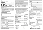
The FX2NC-ENET-ADP is an Ethernet adapter of 10BASE-T specifications for the
FX1S, FX 1N, FX2N and FX2NC Series.
The FX2NC-ENET-ADP enables upload, download, monitor and test sequence of
programs via Ethernet from a personal computer (GX Developer or MX Component
and the virtual COM port driver installed).
Item
3)
5)
Caution
• Use only in the environments specified under the general specifications
in the manual.
Do not use the product in environments with excessive or conductive
dust, corrosive (including salt breeze, Cl 2 , H 2 S, SO 2 , NO 2 , etc.) or
flammable gas, oily smoke, moisture or rain, excessive heat, regular
impact shocks or excessive vibration, as it may result in electrical shock,
fire, malfunction, damage or deterioration of the product.
• Make sure to shut off the external power before installing or wiring it.
Electric shock or serious damage to the product may occur, if the external
power is not disconnected.
• Never drop wire chips or shavings into the ventilation slits when drilling
screw holes or performing wiring, as they may cause fire, breakdown, or
malfunction.
• Securely install the FX2NC-ENET-ADP to the designated port.
A poor connection may result in malfunction.
Withstand voltage
Y0
Y2
Y1
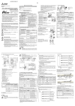
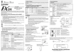
FX1N-CNV-BD
FX1S /FX1N
FX2N-CNV-BD
FX2N
1)
Installation to
FX2NC
4) Affix the above board using the
supplied M3 screws.
Tightening torque: 0.3 to 0.6 N·m
5) Connect the built-in cable of the
FX2NC-ENET-ADP to the port on the left side of the board.
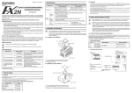
1) Remove the cover from the special adapter port provided on the left side of the
main unit.
2) Connect the built-in cable of the FX2NC-ENET-ADP to the special adapter port.
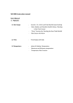
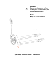
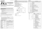
3.2 Installation to a Panel Face
FX Series
PLC
Direct installation to the panel face
Directly attach to the panel face using 2 sets of a
screw (M4), a spring washer, and a flat washer
in the mounting holes.
Tightening torque: 0.7 to 1.0 N·m
For the pitch and positions of mounting screw
holes, refer to the external dimensions.
DIN rail
ENET
-ADP
PC
To lock the tab
Detach
FX2NC-ENET-ADP
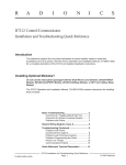
FX1S,FX1N,FX2N
FX2NC
....
LAN
cables
HUB
LAN cables
PLC
Ethernet adapter
LAN cable
FX2NC-ENET-ADP
Twisted pair cable
Category 5(e) STP or 3
STP (straight cable)
FX1S/FX1N PLC + FX1N-CNV-BD
FX2N PLC + FX2N-CNV-BD
TD-
Out
- side of send data
RD+
In
+ side of receive data
7.1 Used devices
7.3 Parameter setting examples for FX2NC-ENET-ADP
4
Unused
--
5
Unused
--
[FX1S]
Set the Ethernet parameters to nine data registers from D128 to D136.
Two examples of setting the Ethernet parameters for the FX2NC-ENET-ADP are shown
below:
Example of parameter settings
6
RD-
In
7
Unused
--
8
Unused
--
Description
STP (Shielded twisted pair) cable Category 5(e) or 3
D132, D133
Subnet mask*4
255.255.255.0
Set the sub-net mask for
connecting to Ethernet.*3
6. Wiring
D134, D135
Gateway
address*4
192.168.0.1
Set the gateway address for
connecting to Ethernet.*2
D136
TCP port
number
1024
Set the TCP ports within the
range from 1024 to 65535.
6.1 Cautions on wiring
Wiring Precaution
• Cut off all phases of external power source before installation or
performing wiring work in order to avoid electric shock or damage to
the product.
Wiring Precaution
• The grounding terminal in the main unit should be connected to a
grounding resistance of 100Ω or less.
• Do not drop cuttings and wire chips into the ventilation slits of the
PLC when drilling screw holes or performing wiring work.
Otherwise, fire, failure, or malfunction may occur.
PLC
Another
equipment
Dedicated grounding
(best)
PLC
Another
equipment
Shared grounding (good)
PLC
Another
equipment
Common grounding
(not possible)
[FX1N/FX2N/FX2NC]
Set the Ethernet parameters to nine data registers from D1000 to D1008.
If these data registers are used for any other purpose, the Ethernet parameters can be
set to nine data registers 'D' starting from D2000, D3000, D4000, D5000, D6000 or
D7000.
Data register
Setting item
Default
parameter
D!000,D!001
Header*1
-
D!002,D!003
IP address*4
192.168.0.100
Description
Set H454E4554 ("ENET").
Set the IP address for
connecting to Ethernet.*2
Subnet mask*4
255.255.255.0
D!006,D!007
Gateway
address*4
192.168.0.1
Set the gateway address for
connecting to Ethernet.*2
D!008
TCP port
number
1024
Set the TCP ports within the
range from 1024 to 65535.
Grounding
(100Ω or less)
Setting item
Parameter
Set data
Header
"ENET"
H454E4554
D1002,D1003
IP address
192.168.0.110
HC0A8006E
D1004,D1005
Subnet mask
255.255.255.0
HFFFFFF00
D1006,D1007
Gateway address
192.168.0.1
HC0A80001
D1008
TCP port number
1024
K1024
FX1N/FX2N/FX2NC
D128,D129
D1000,D1001
D130,D131
D132,D133
D134,D135
D136
M8002
D MOV H454E4554
D128
Setting of Header:
ASCII codes to specify
"ENET"
D MOV HC0A8006E
D130
Setting of IP address*6:
192 . 168 . 0 . 110
C0 A8 00 6E
D MOV HFFFFFF00
D132
Setting of Subnet mask:
255 . 255 . 255 . 0
FF FF FF 00
D134
Setting of Gateway
address:
192 . 168 . 0 . 1
C0 A8 00 01
Note
MOV
D136
TCP Port number:1024
.
.
.
K1024
[FX1N/FX2N/FX2NC]
M8002
D MOV H454E4554 D1000
Setting of Header:
ASCII codes to specify
"ENET"
D MOV HC0A8006E D1002
Setting of IP address*6:
192 . 168 . 0 . 110
C0 A8 00 6E
D MOV HFFFFFF00 D1004
Setting of Subnet mask:
255 . 255 . 255 . 0
FF FF FF 00
Set numbers from 1 to 223.
*3 In the following cases (and as explained in *2) concerning the Subnet mask data,
the RD LED will be lit when the FX2NC -ENET-ADP is turned on, an error will
occur and Ethernet communication will not be performed.
(The following conditions are expressed in binary form.)
1) If 1 is set for all bits
2) If 0 is set for all bits
3) If 1 is set immediately after 0 is set
Example: 111...11000100...
*4 The settings of the IP address, Subnet mask and Gateway address depend on
the customer's network environment. For the contents of these parameters, see
the network administrator.
*5 The FX2NC-ENET-ADP searches for the header in the order "D1000 → D7000".
The values described in lowest data resister numbers are set as the Ethernet
parameters.
SD
2) 3)
4)
5)
7)
6)
9)
11)
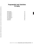
7(0.28")
(Height of screw hole)
74(2.92")
10)
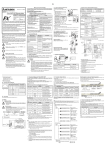
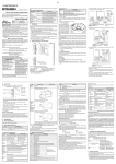
1) Mounting hole (2-φ4.2)
Used when FX2NC-ENET-ADP is mounted directly.
Not used when the module is mounted on DIN rail.
2) POWER LED (green)
Lit while 5V DC power is supplied from the PLC.
3) LINK LED (green)
Lit while the HUB is connected by an RJ45 connector and the power is on.
4) ACT LED (red)
Lit while transferring data with connected Ethernet.
5) SD LED (red)
Lit while sending data to the connected PLC.
6) RD LED (red)
Lit while receiving data from the connected PLC.
7) Connecting cable
Used to connect the main unit.
8) RJ45 connector
Connects the Ethernet cable.
9) Terminal block for grounding
Internally short-circuited.
Applicable cable: AWG 17 to 14
Tightening torque: 0.4 to 0.5 N·m
10)DIN rail mounting hook
11)DIN rail mounting groove
When file registers are used to set the Ethernet parameters
Select [Parameter] - [PLC parameter] - [Memory capacity] in GX Developer, and
set the file register capacity to 1 block or more.
Then, right-click [Device memory], add the device memory data, and set the
parameters as shown below:
• Settings of D128 to D135 or D1000 to D1007 (32-bit HEX mode)
Header: ENET
Subnet mask:
255.255.255.0
Gateway address:
192.168.0.1
• Settings of D136 or D1008 (16-bit DEC mode)
TCP port number: 1024
7.4 Check of configuration using SD LED and RD LED
Note
In the FX2NC-ENET-ADP, the Ethernet parameters become valid only when the power
is turned ON and the setting data is stored in specified data registers.
In either of the following cases, turn off the power of the PLC once, and then turn it on
again.
• When a parameter is set for the first time
• When the setting of a parameter is changed during operation
[FX1S]
D MOV HC0A80001
*2 The first 8 bits used for the IP address and Gateway address must be in the
range from 1 to 223.
If any number outside this range is used, the RD LED will be lit when the FX2NCENET-ADP is turned on and Ethernet communication will not be performed.
ACT
IP address: 192.168.0.110
• If "ENET" is not found or the parameters such as IP address, Gateway address,
Subnet mask are incorrect, the default parameters are valid.
• If FX 2NC-ENET-ADAP cannot read out the specified data register stored in the PLC,
the default parameters are used. In such a case, the SD or RD LED is lit.
(Refer to 7.4.)
*1 This is the header identifier required when FX2NC-ENET-ADP identifies the
Ethernet parameters.
Make sure to set H454E4554 ("ENET") to D128/D129 or D!000/D!001.
LINK
When the PLC program is used to set the Ethernet parameters
The Ethernet parameters for the FX2NC-ENET-ADP can be set using the program
shown below:
!: Indicates any number in the range from 1 to 7.
To
HUB
Unit: mm (inches)
Data register
FX1S
Set the sub-net mask for
connecting to Ethernet.*3
D!004,D!005
6.2 Wiring example
0.1 kg (0.22 lbs)
78(3.08")
3
192.168.0.100
3 pins
(However, internally short-circuited)
19.1
(0.76")
2
IP address*4
To ground
1)
+ side of send data
D130, D131
RJ45 connector
8)
Dismounting from DIN rail
Slightly pull down the DIN rail mounting clip
using a tool such as a slotted screwdriver. Pull
down the clip further, and the rail will be locked
with the clip left open.
Out
5.4 Used cable
Full duplex
To Ethernet
FX Series
PLC
Direction
Set the IP address for
connecting to Ethernet.*2
Star type
Communication
method
RD
TD+
Set H454E4554 ("ENET").
10BASE-T
Topology
Mass
1)
Signal name
-
Transmission media
POWER
1
Header
CSMA/CD(IEEE802.3)
FX 2NC-ENET-ADP
Pin
D128, D129
10Mbps
Protocol
Connector
Mounting on DIN rail
Affix the FX2NC-ENET-ADP to the DIN rail,
DIN46277 (35 mm (1.37") wide).
Set the Ethernet parameters using either of the following methods through serial
communication:
• Setting using the PLC program
• Setting using file registers
For each setting example, refer to Section 7.3.
Default
parameter
Baud rate
2-φ4.2(0.17")
7.2 Parameter setting methods
*1*5
5V DC, 135 mA (supplied from PLC)
16.1(0.64")
(to screw holes)
ENET
-ADP
To connect the FX2NC-ENET-ADP to the Ethernet, it is necessary to set the Ethernet
parameters, including the Header, IP address, Subnet mask, Gateway address and
TCP port number.
Set the Ethernet parameters to the 'D' data registers in the PLC.
Immediately after the power is turned on, the FX2NC-ENET-ADP reads the Ethernet
parameters stored in the 'D' data registers in the PLC, and configures itself.
Setting item
500V AC for 1 min Conforms to JEM1021, between all
terminals together
5 MΩ or more by
500V DC megger and grounding
terminal
5.2 Outside dimensions and name of each part
7. Parameter Settings for FX2NC-ENET-ADP
Data register
Supply voltage/
current
Performance
specifications
The RJ45 connector in the FX2NC-ENET-ADP has the following pin arrangement.
- side of receive data
Power supply
specifications
2)
5.3 Connector pin arrangement
1
Insulation resistance
Installation to FX2NC
Turn OFF the PLC before beginning any work.
FX2NC PLC
8
General
specifications
Corresponding
model
Board name
• Compatible version of GX Developer
Ver. 8.12N or later
• Compatible version of MX Component
Ver. 3.05F or later
Description
Description
X3
X1
2)
4. System Configuration
3. Installation
TRANSPORTATION AND MAINTENANCE PRECAUTIONS
• During transportation avoid any impact as the module is a precision
instrument. Doing so could cause trouble in the module.
• It is necessary to check the operation of module after transportation,
in case of any impact damage.
5.1 Specifications
The general specifications of FX2NC-ENET-ADP are same as those of the FX
Series PLC except the following items.
4)
Describes matters related
to the installation of the
boards.
For GX Developer and MX Component, refer to the operation manual respectively.
INSTALLATION PRECAUTIONS
• Use the module in an environment that meets the general
specifications contained in this manual. Using this module in an
environment outside the range of the general specifications could
result in electric shock, fire, erroneous operation, and damage to or
deterioration of the product.
• Do not disassemble or modify the module. Doing so may cause
failure, malfunction, injury, or fire.
1)
Screws
2. Outline of Product
3) Indicates a point of further interest or further explanation.
Installation to
FX1S/FX1N/FX2N
45 (1.78")
(to center of DIN rail)
Manual Number
Installation to FX1S/FX1N/FX 2N
Turn OFF the PLC before beginning any
work.
1) Remove the panel cover from the top
face of the main unit.
2) Take off the resin cover from the left
side of the main unit.
3) Install the following board to the port
on the main unit.
10
(0.40")
USER'S MANUAL
5. Product Specification
3.1 How to Install to FX Series PLC
65.5(2.58")
(between screw holes)
90(3.35")
FX2NC-ENET-ADP Ethernet adapter
● Note Concerning the CE Marking●
●
The CE marking does not guarantee that an entire mechanical module produced in
accordance with the contents of the notification comply with the following standards.
Compliance to EMC standards of the entire mechanical module should be checked by
the user / manufacturer.
Standards with which this product complies
Type : Programmable Controller (Open Type Equipment)
Models : Products manufactured from April 1st, 2004.
Electromagnetic Compatibility Standards
Remark
(EMC)
EN61000-6-4:2001
Compliance with all relevant aspects
Electromagnetic compatibility
of the standard. (Radiated Emissions
-Generic standards - Emission standard for and Mains Terminal Voltage
Industrial environment
Emissions)
EN61131-2:1994 Programmable controllers Compliance with all relevant aspects
/A11: 1996 -Equipment requirements and of the standard. (RF Immunity, Fast
tests
transients, ESD and Damped
/A12: 2000
oscillatory wave)
Compliance with all relevant aspects
EN61000-6-2:2001
of the standard. (RF immunity, Fast
Electromagnetic compatibility
transients, ESD, Conducted, Surges,
-Generic standards Immunity for industrial Power magnetic fields, Voltage dips
environments.
and Voltage interruptions)
D MOV HC0A80001 D1006
Setting of Gateway
address:
192 . 168 . 0 . 1
C0 A8 00 01
MOV
TCP Port number:1024
K1024
D1008
*6 When connecting two or more PLCs to a network, do not use the same IP
address twice.
Example: Personal computer (GX Developer) 192 . 168 . 0 . 10
PLC1
192 . 168 . 0 . 110
PLC2
192 . 168 . 0 . 111
The SD LED and the RD LED can be used to check whether the current
configuration is functioning properly or not.
At startup (reset)
After power is turned on, the SD LED and RD LED are lit for 2 seconds, and the
FX2NC-ENET-ADP reads the configuration data from the PLC.
If the configuration data is read correctly, the SD LED and RD LED turn off. If an
error occurs, the SD LED and RD LED indicate the error status as shown below:
SD LED
RD LED
Description
1)
ON
OFF
The contents of data registers in the PLC cannot be
read.
2)
OFF
ON
The header "ENET" cannot be detected.
A parameter such as IP address, Gateway address,
Subnet mask and TCP port number is invalid.
3)
OFF
OFF
Valid
Note
In case of 1) or 2), the parameters such as IP address, Gateway address, Subnet
mask are incorrect and the default parameters are valid.
JY997D12301
Revision
B
Date
July. 2004
• This manual contains text, diagrams and explanations which guide the
reader in the correct installation and operation of the FX2NC -ENET-ADP
Ethernet adapter. It should be read and understood before attempting to use
the unit.
• If in doubt at any stage of the installation of FX2NC-ENET-ADP, consult a
professional electrical technician who is qualified and trained to the local
and national standards which apply to the installation site.
• If in doubt about the operation or use of the FX2NC-ENET-ADP, please
consult the nearest Mitsubishi Electric distributor.
• This manual is subject to change without notice.
• Microsoft Windows is either registered Tactical or trademarks of Microsoft
Corporation in the United States and/or other countries.
• Tactical Software is a registered trademark and Serial/IP is a trademark of
Tactical Software, LLC.
• The company name and the product name described in this manual are the
registered trademarks or trademarks of each company.
Guideline for the safety of the user and protection of the FX2NC-ENET-ADP.
This manual provides usage information for the FX2NC-ENET-ADP Ethernet
adapter. The manual has been written to be used by trained and competent
personnel.
Notes on the symbols used in this manual
At various times throughout out this manual certain symbols will be used to
highlight points of information which are intended to ensure the users personal
safety and protect the integrity of equipment. Whenever any of the following
symbols are encountered, its associated note must be read and understood. Each
of the symbols used will now be listed with a brief description of its meaning.
Hardware Warnings
1) Indicates that the identified danger WILL cause physical and
property damage.
2) Indicates that the identified danger could POSSIBLY cause
physical and property damage.
For more details please contact the local Mitsubishi Electric sales site.
- Notes for compliance to the EMC regulation.
It is necessary to install the FX2NC-ENET-ADP module in a shielded metal control
panel.
1. Associated Manuals
PROGRAMMING MANUAL II mentioned below is not included with the product.
If required, please consult the Mitsubishi Electric sales site where the product was
purchased.
Manual name
Manual No.
FX1S HARDWARE MANUAL
JY992D83901
FX1N HARDWARE MANUAL
JY992D89301
FX2N HARDWARE MANUAL
JY992D66301
FX2NC HARDWARE MANUAL
(DSS/DS)
(D/UL)
JY992D76401
JY992D87201
PROGRAMMING MANUAL II
JY992D88101
FX1N-CNV-BD Special Adapter
Connection Board
JY992D84701
FX2N-CNV-BD Special Adapter
Connection Board
JY992D63601
Description
Describes the hardware of
the FX Series PLC such as
specifications, wiring, and
installation.
DISPOSAL PRECAUTIONS
• When disposing of this product, treat it as industrial waste.
Describes the instructions
available in the FX 1S/FX1N/
FX2N/FX2NC Series PLC.
The FX2NC-ENET-ADP is an Ethernet adapter of 10BASE-T specifications for the
FX1S, FX 1N, FX2N and FX2NC Series.
The FX2NC-ENET-ADP enables upload, download, monitor and test sequence of
programs via Ethernet from a personal computer (GX Developer or MX Component
and the virtual COM port driver installed).
Item
3)
5)
Caution
• Use only in the environments specified under the general specifications
in the manual.
Do not use the product in environments with excessive or conductive
dust, corrosive (including salt breeze, Cl 2 , H 2 S, SO 2 , NO 2 , etc.) or
flammable gas, oily smoke, moisture or rain, excessive heat, regular
impact shocks or excessive vibration, as it may result in electrical shock,
fire, malfunction, damage or deterioration of the product.
• Make sure to shut off the external power before installing or wiring it.
Electric shock or serious damage to the product may occur, if the external
power is not disconnected.
• Never drop wire chips or shavings into the ventilation slits when drilling
screw holes or performing wiring, as they may cause fire, breakdown, or
malfunction.
• Securely install the FX2NC-ENET-ADP to the designated port.
A poor connection may result in malfunction.
Withstand voltage
Y0
Y2
Y1
FX1N-CNV-BD
FX1S /FX1N
FX2N-CNV-BD
FX2N
1)
Installation to
FX2NC
4) Affix the above board using the
supplied M3 screws.
Tightening torque: 0.3 to 0.6 N·m
5) Connect the built-in cable of the
FX2NC-ENET-ADP to the port on the left side of the board.
1) Remove the cover from the special adapter port provided on the left side of the
main unit.
2) Connect the built-in cable of the FX2NC-ENET-ADP to the special adapter port.
3.2 Installation to a Panel Face
FX Series
PLC
Direct installation to the panel face
Directly attach to the panel face using 2 sets of a
screw (M4), a spring washer, and a flat washer
in the mounting holes.
Tightening torque: 0.7 to 1.0 N·m
For the pitch and positions of mounting screw
holes, refer to the external dimensions.
DIN rail
ENET
-ADP
PC
To lock the tab
Detach
FX2NC-ENET-ADP
FX1S,FX1N,FX2N
FX2NC
....
LAN
cables
HUB
LAN cables
PLC
Ethernet adapter
LAN cable
FX2NC-ENET-ADP
Twisted pair cable
Category 5(e) STP or 3
STP (straight cable)
FX1S/FX1N PLC + FX1N-CNV-BD
FX2N PLC + FX2N-CNV-BD
TD-
Out
- side of send data
RD+
In
+ side of receive data
7.1 Used devices
7.3 Parameter setting examples for FX2NC-ENET-ADP
4
Unused
--
5
Unused
--
[FX1S]
Set the Ethernet parameters to nine data registers from D128 to D136.
Two examples of setting the Ethernet parameters for the FX2NC-ENET-ADP are shown
below:
Example of parameter settings
6
RD-
In
7
Unused
--
8
Unused
--
Description
STP (Shielded twisted pair) cable Category 5(e) or 3
D132, D133
Subnet mask*4
255.255.255.0
Set the sub-net mask for
connecting to Ethernet.*3
6. Wiring
D134, D135
Gateway
address*4
192.168.0.1
Set the gateway address for
connecting to Ethernet.*2
D136
TCP port
number
1024
Set the TCP ports within the
range from 1024 to 65535.
6.1 Cautions on wiring
Wiring Precaution
• Cut off all phases of external power source before installation or
performing wiring work in order to avoid electric shock or damage to
the product.
Wiring Precaution
• The grounding terminal in the main unit should be connected to a
grounding resistance of 100Ω or less.
• Do not drop cuttings and wire chips into the ventilation slits of the
PLC when drilling screw holes or performing wiring work.
Otherwise, fire, failure, or malfunction may occur.
PLC
Another
equipment
Dedicated grounding
(best)
PLC
Another
equipment
Shared grounding (good)
PLC
Another
equipment
Common grounding
(not possible)
[FX1N/FX2N/FX2NC]
Set the Ethernet parameters to nine data registers from D1000 to D1008.
If these data registers are used for any other purpose, the Ethernet parameters can be
set to nine data registers 'D' starting from D2000, D3000, D4000, D5000, D6000 or
D7000.
Data register
Setting item
Default
parameter
D!000,D!001
Header*1
-
D!002,D!003
IP address*4
192.168.0.100
Description
Set H454E4554 ("ENET").
Set the IP address for
connecting to Ethernet.*2
Subnet mask*4
255.255.255.0
D!006,D!007
Gateway
address*4
192.168.0.1
Set the gateway address for
connecting to Ethernet.*2
D!008
TCP port
number
1024
Set the TCP ports within the
range from 1024 to 65535.
Grounding
(100Ω or less)
Setting item
Parameter
Set data
Header
"ENET"
H454E4554
D1002,D1003
IP address
192.168.0.110
HC0A8006E
D1004,D1005
Subnet mask
255.255.255.0
HFFFFFF00
D1006,D1007
Gateway address
192.168.0.1
HC0A80001
D1008
TCP port number
1024
K1024
FX1N/FX2N/FX2NC
D128,D129
D1000,D1001
D130,D131
D132,D133
D134,D135
D136
M8002
D MOV H454E4554
D128
Setting of Header:
ASCII codes to specify
"ENET"
D MOV HC0A8006E
D130
Setting of IP address*6:
192 . 168 . 0 . 110
C0 A8 00 6E
D MOV HFFFFFF00
D132
Setting of Subnet mask:
255 . 255 . 255 . 0
FF FF FF 00
D134
Setting of Gateway
address:
192 . 168 . 0 . 1
C0 A8 00 01
Note
MOV
D136
TCP Port number:1024
.
.
.
K1024
[FX1N/FX2N/FX2NC]
M8002
D MOV H454E4554 D1000
Setting of Header:
ASCII codes to specify
"ENET"
D MOV HC0A8006E D1002
Setting of IP address*6:
192 . 168 . 0 . 110
C0 A8 00 6E
D MOV HFFFFFF00 D1004
Setting of Subnet mask:
255 . 255 . 255 . 0
FF FF FF 00
Set numbers from 1 to 223.
*3 In the following cases (and as explained in *2) concerning the Subnet mask data,
the RD LED will be lit when the FX2NC -ENET-ADP is turned on, an error will
occur and Ethernet communication will not be performed.
(The following conditions are expressed in binary form.)
1) If 1 is set for all bits
2) If 0 is set for all bits
3) If 1 is set immediately after 0 is set
Example: 111...11000100...
*4 The settings of the IP address, Subnet mask and Gateway address depend on
the customer's network environment. For the contents of these parameters, see
the network administrator.
*5 The FX2NC-ENET-ADP searches for the header in the order "D1000 → D7000".
The values described in lowest data resister numbers are set as the Ethernet
parameters.
SD
2) 3)
4)
5)
7)
6)
9)
11)
7(0.28")
(Height of screw hole)
74(2.92")
10)
1) Mounting hole (2-φ4.2)
Used when FX2NC-ENET-ADP is mounted directly.
Not used when the module is mounted on DIN rail.
2) POWER LED (green)
Lit while 5V DC power is supplied from the PLC.
3) LINK LED (green)
Lit while the HUB is connected by an RJ45 connector and the power is on.
4) ACT LED (red)
Lit while transferring data with connected Ethernet.
5) SD LED (red)
Lit while sending data to the connected PLC.
6) RD LED (red)
Lit while receiving data from the connected PLC.
7) Connecting cable
Used to connect the main unit.
8) RJ45 connector
Connects the Ethernet cable.
9) Terminal block for grounding
Internally short-circuited.
Applicable cable: AWG 17 to 14
Tightening torque: 0.4 to 0.5 N·m
10)DIN rail mounting hook
11)DIN rail mounting groove
When file registers are used to set the Ethernet parameters
Select [Parameter] - [PLC parameter] - [Memory capacity] in GX Developer, and
set the file register capacity to 1 block or more.
Then, right-click [Device memory], add the device memory data, and set the
parameters as shown below:
• Settings of D128 to D135 or D1000 to D1007 (32-bit HEX mode)
Header: ENET
Subnet mask:
255.255.255.0
Gateway address:
192.168.0.1
• Settings of D136 or D1008 (16-bit DEC mode)
TCP port number: 1024
7.4 Check of configuration using SD LED and RD LED
Note
In the FX2NC-ENET-ADP, the Ethernet parameters become valid only when the power
is turned ON and the setting data is stored in specified data registers.
In either of the following cases, turn off the power of the PLC once, and then turn it on
again.
• When a parameter is set for the first time
• When the setting of a parameter is changed during operation
[FX1S]
D MOV HC0A80001
*2 The first 8 bits used for the IP address and Gateway address must be in the
range from 1 to 223.
If any number outside this range is used, the RD LED will be lit when the FX2NCENET-ADP is turned on and Ethernet communication will not be performed.
ACT
IP address: 192.168.0.110
• If "ENET" is not found or the parameters such as IP address, Gateway address,
Subnet mask are incorrect, the default parameters are valid.
• If FX 2NC-ENET-ADAP cannot read out the specified data register stored in the PLC,
the default parameters are used. In such a case, the SD or RD LED is lit.
(Refer to 7.4.)
*1 This is the header identifier required when FX2NC-ENET-ADP identifies the
Ethernet parameters.
Make sure to set H454E4554 ("ENET") to D128/D129 or D!000/D!001.
LINK
When the PLC program is used to set the Ethernet parameters
The Ethernet parameters for the FX2NC-ENET-ADP can be set using the program
shown below:
!: Indicates any number in the range from 1 to 7.
To
HUB
Unit: mm (inches)
Data register
FX1S
Set the sub-net mask for
connecting to Ethernet.*3
D!004,D!005
6.2 Wiring example
0.1 kg (0.22 lbs)
78(3.08")
3
192.168.0.100
3 pins
(However, internally short-circuited)
19.1
(0.76")
2
IP address*4
To ground
1)
+ side of send data
D130, D131
RJ45 connector
8)
Dismounting from DIN rail
Slightly pull down the DIN rail mounting clip
using a tool such as a slotted screwdriver. Pull
down the clip further, and the rail will be locked
with the clip left open.
Out
5.4 Used cable
Full duplex
To Ethernet
FX Series
PLC
Direction
Set the IP address for
connecting to Ethernet.*2
Star type
Communication
method
RD
TD+
Set H454E4554 ("ENET").
10BASE-T
Topology
Mass
1)
Signal name
-
Transmission media
POWER
1
Header
CSMA/CD(IEEE802.3)
FX 2NC-ENET-ADP
Pin
D128, D129
10Mbps
Protocol
Connector
Mounting on DIN rail
Affix the FX2NC-ENET-ADP to the DIN rail,
DIN46277 (35 mm (1.37") wide).
Set the Ethernet parameters using either of the following methods through serial
communication:
• Setting using the PLC program
• Setting using file registers
For each setting example, refer to Section 7.3.
Default
parameter
Baud rate
2-φ4.2(0.17")
7.2 Parameter setting methods
*1*5
5V DC, 135 mA (supplied from PLC)
16.1(0.64")
(to screw holes)
ENET
-ADP
To connect the FX2NC-ENET-ADP to the Ethernet, it is necessary to set the Ethernet
parameters, including the Header, IP address, Subnet mask, Gateway address and
TCP port number.
Set the Ethernet parameters to the 'D' data registers in the PLC.
Immediately after the power is turned on, the FX2NC-ENET-ADP reads the Ethernet
parameters stored in the 'D' data registers in the PLC, and configures itself.
Setting item
500V AC for 1 min Conforms to JEM1021, between all
terminals together
5 MΩ or more by
500V DC megger and grounding
terminal
5.2 Outside dimensions and name of each part
7. Parameter Settings for FX2NC-ENET-ADP
Data register
Supply voltage/
current
Performance
specifications
The RJ45 connector in the FX2NC-ENET-ADP has the following pin arrangement.
- side of receive data
Power supply
specifications
2)
5.3 Connector pin arrangement
1
Insulation resistance
Installation to FX2NC
Turn OFF the PLC before beginning any work.
FX2NC PLC
8
General
specifications
Corresponding
model
Board name
• Compatible version of GX Developer
Ver. 8.12N or later
• Compatible version of MX Component
Ver. 3.05F or later
Description
Description
X3
X1
2)
4. System Configuration
3. Installation
TRANSPORTATION AND MAINTENANCE PRECAUTIONS
• During transportation avoid any impact as the module is a precision
instrument. Doing so could cause trouble in the module.
• It is necessary to check the operation of module after transportation,
in case of any impact damage.
5.1 Specifications
The general specifications of FX2NC-ENET-ADP are same as those of the FX
Series PLC except the following items.
4)
Describes matters related
to the installation of the
boards.
For GX Developer and MX Component, refer to the operation manual respectively.
INSTALLATION PRECAUTIONS
• Use the module in an environment that meets the general
specifications contained in this manual. Using this module in an
environment outside the range of the general specifications could
result in electric shock, fire, erroneous operation, and damage to or
deterioration of the product.
• Do not disassemble or modify the module. Doing so may cause
failure, malfunction, injury, or fire.
1)
Screws
2. Outline of Product
3) Indicates a point of further interest or further explanation.
Installation to
FX1S/FX1N/FX2N
45 (1.78")
(to center of DIN rail)
Manual Number
Installation to FX1S/FX1N/FX 2N
Turn OFF the PLC before beginning any
work.
1) Remove the panel cover from the top
face of the main unit.
2) Take off the resin cover from the left
side of the main unit.
3) Install the following board to the port
on the main unit.
10
(0.40")
USER'S MANUAL
5. Product Specification
3.1 How to Install to FX Series PLC
65.5(2.58")
(between screw holes)
90(3.35")
FX2NC-ENET-ADP Ethernet adapter
● Note Concerning the CE Marking●
●
The CE marking does not guarantee that an entire mechanical module produced in
accordance with the contents of the notification comply with the following standards.
Compliance to EMC standards of the entire mechanical module should be checked by
the user / manufacturer.
Standards with which this product complies
Type : Programmable Controller (Open Type Equipment)
Models : Products manufactured from April 1st, 2004.
Electromagnetic Compatibility Standards
Remark
(EMC)
EN61000-6-4:2001
Compliance with all relevant aspects
Electromagnetic compatibility
of the standard. (Radiated Emissions
-Generic standards - Emission standard for and Mains Terminal Voltage
Industrial environment
Emissions)
EN61131-2:1994 Programmable controllers Compliance with all relevant aspects
/A11: 1996 -Equipment requirements and of the standard. (RF Immunity, Fast
tests
transients, ESD and Damped
/A12: 2000
oscillatory wave)
Compliance with all relevant aspects
EN61000-6-2:2001
of the standard. (RF immunity, Fast
Electromagnetic compatibility
transients, ESD, Conducted, Surges,
-Generic standards Immunity for industrial Power magnetic fields, Voltage dips
environments.
and Voltage interruptions)
D MOV HC0A80001 D1006
Setting of Gateway
address:
192 . 168 . 0 . 1
C0 A8 00 01
MOV
TCP Port number:1024
K1024
D1008
*6 When connecting two or more PLCs to a network, do not use the same IP
address twice.
Example: Personal computer (GX Developer) 192 . 168 . 0 . 10
PLC1
192 . 168 . 0 . 110
PLC2
192 . 168 . 0 . 111
The SD LED and the RD LED can be used to check whether the current
configuration is functioning properly or not.
At startup (reset)
After power is turned on, the SD LED and RD LED are lit for 2 seconds, and the
FX2NC-ENET-ADP reads the configuration data from the PLC.
If the configuration data is read correctly, the SD LED and RD LED turn off. If an
error occurs, the SD LED and RD LED indicate the error status as shown below:
SD LED
RD LED
Description
1)
ON
OFF
The contents of data registers in the PLC cannot be
read.
2)
OFF
ON
The header "ENET" cannot be detected.
A parameter such as IP address, Gateway address,
Subnet mask and TCP port number is invalid.
3)
OFF
OFF
Valid
Note
In case of 1) or 2), the parameters such as IP address, Gateway address, Subnet
mask are incorrect and the default parameters are valid.
8. Virtual COM Port (VCP) Driver
9. Settings in GX Developer
Install the virtual COM port driver on the personal computer in which GX
Developer is installed, and set the properties to the virtual COM port.
Set the information of the connected PLC (IP address and TCP port number) as
the properties.
Recommended driver
Serial/IP by Tactical Software (http://www.tactical-sw.com)
Settings in the Serial/IP (Version 4.1 is shown as an example.)
1) Set the virtual COM port to be added at [Select Ports].
2) Set the following items at [Configuration Wizard]:
- IP Address of Server: IP address of the FX2NC-ENET-ADP
- Port Number: TCP port number
9.1 Setting method
Select "Host station".
Select [Online] - [Connection setup] - [PC side I/F Serial setting], and select a COM
port set in the Serial/IP.
Select a COM port.
Select the Logical station number
before clicking the Next button.
2)
[Next]
[Next]
Select "Serial".
Note
The Transmission speed setting in GX Developer is ignored.
Use these items
in the default
settings.
9.2 Operations
In GX Developer, operations such as upload, download, monitoring and test of a
program are performed in the same way as with serial communication.
10. Setting in MX Component
10.1 Setting method
Select a COM port.
1)
Select [Programs] - [MELSOFT Application] - [MX Component] - [Communication
Setup Utility], and select a COM port set in the Serial/IP.
Set the TCP
port number.
Set the IP address.
Enter a comment.
Select a COM port.
[Next]
[Finish]
Select "CPU module".
[Wizard]
Note
Make sure that the IP address and TCP port number set in the Serial/IP are
equivalent to the Ethernet parameters set in the PLC.
FX 1S/FX 1N/FX 2N(C)
Note
The Transmission speed setting in MX Component is ignored.
[Next]
11. Troubleshooting
Turn ON power of PLC.
Is POWER
LED ON?
No
Check the cable connection between
FX2NC-ENET-ADP and PLC.
No
Check if FX2NC-ENET-ADP and HUB are
connected correctly.
Check if power of HUB is ON.
Yes
Is LINK
LED ON?
Yes
Two seconds after
FX2NC-ENET-ADP is
turned ON
SD LED:ON
RD LED:OFF
Execute PING
command for IP
address set to PLC.*
No
SD LED:OFF
RD LED:ON
Yes
Yes
Are FX2NC-ENET-ADP
and PLC connected
correctly?
No
No
Connect
cable
correctly.
Check Ethernet
parameters.
For details, refer
to "7. Parameter
Settings for
FX2NC-ENETADP".
SD LED:OFF
RD LED:OFF
Yes
Parameters
are read
correctly
from PLC.
Any response?
No
1) Check again IP address set to PLC.
2) Confirm that network address in PLC
matches network address in PC.
3) Confirm connection of Ethernet
between PC and PLC.
Yes
Confirm that TCP port number set in virtual
COM port driver matches TCP port number
set in PLC.
Yes
Turn ON power again.
Is communication
port set for computer
link or no protocol
communication?
(Value other than 0
stored in D8120.)
Is any
numeric value
other than 0 stored in
D8120?
No
Yes
Yes
Clear communication
parameter check box,
and download
program.
Set 0 to D8120.
Turn ON power again.
Clear the check box.
Check if PLC and PC
are connected
correctly.
* [Reference]
The PING command confirms confirmation whether the communication
between Ethernet devices using the IP address of TCP/IP is possible.
Execute the PING command from the PC connected to Ethernet, and
check whether the FX2NC-ENET-ADP sends a response.
Refer to the PING command described below.
Executing the PING command
Open the MS-DOS prompt (command prompt in the Windows2000/XP).
In the example above, the IP address is set to "192.168.0.110".
PING 192.168.0.110
HEAD OFFICE : MITSUBISHI DENKI BLDG MARUNOUTI TOKYO 100-8310
HIMEJI WORKS : 840, CHIYODA CHO, HIMEJI, JAPAN
JY997D12301
Revision
B
Date
July. 2004
• This manual contains text, diagrams and explanations which guide the
reader in the correct installation and operation of the FX2NC -ENET-ADP
Ethernet adapter. It should be read and understood before attempting to use
the unit.
• If in doubt at any stage of the installation of FX2NC-ENET-ADP, consult a
professional electrical technician who is qualified and trained to the local
and national standards which apply to the installation site.
• If in doubt about the operation or use of the FX2NC-ENET-ADP, please
consult the nearest Mitsubishi Electric distributor.
• This manual is subject to change without notice.
• Microsoft Windows is either registered Tactical or trademarks of Microsoft
Corporation in the United States and/or other countries.
• Tactical Software is a registered trademark and Serial/IP is a trademark of
Tactical Software, LLC.
• The company name and the product name described in this manual are the
registered trademarks or trademarks of each company.
Guideline for the safety of the user and protection of the FX2NC-ENET-ADP.
This manual provides usage information for the FX2NC-ENET-ADP Ethernet
adapter. The manual has been written to be used by trained and competent
personnel.
Notes on the symbols used in this manual
At various times throughout out this manual certain symbols will be used to
highlight points of information which are intended to ensure the users personal
safety and protect the integrity of equipment. Whenever any of the following
symbols are encountered, its associated note must be read and understood. Each
of the symbols used will now be listed with a brief description of its meaning.
Hardware Warnings
1) Indicates that the identified danger WILL cause physical and
property damage.
2) Indicates that the identified danger could POSSIBLY cause
physical and property damage.
For more details please contact the local Mitsubishi Electric sales site.
- Notes for compliance to the EMC regulation.
It is necessary to install the FX2NC-ENET-ADP module in a shielded metal control
panel.
1. Associated Manuals
PROGRAMMING MANUAL II mentioned below is not included with the product.
If required, please consult the Mitsubishi Electric sales site where the product was
purchased.
Manual name
Manual No.
FX1S HARDWARE MANUAL
JY992D83901
FX1N HARDWARE MANUAL
JY992D89301
FX2N HARDWARE MANUAL
JY992D66301
FX2NC HARDWARE MANUAL
(DSS/DS)
(D/UL)
JY992D76401
JY992D87201
PROGRAMMING MANUAL II
JY992D88101
FX1N-CNV-BD Special Adapter
Connection Board
JY992D84701
FX2N-CNV-BD Special Adapter
Connection Board
JY992D63601
Description
Describes the hardware of
the FX Series PLC such as
specifications, wiring, and
installation.
DISPOSAL PRECAUTIONS
• When disposing of this product, treat it as industrial waste.
Describes the instructions
available in the FX 1S/FX1N/
FX2N/FX2NC Series PLC.
The FX2NC-ENET-ADP is an Ethernet adapter of 10BASE-T specifications for the
FX1S, FX 1N, FX2N and FX2NC Series.
The FX2NC-ENET-ADP enables upload, download, monitor and test sequence of
programs via Ethernet from a personal computer (GX Developer or MX Component
and the virtual COM port driver installed).
Item
3)
5)
Caution
• Use only in the environments specified under the general specifications
in the manual.
Do not use the product in environments with excessive or conductive
dust, corrosive (including salt breeze, Cl 2 , H 2 S, SO 2 , NO 2 , etc.) or
flammable gas, oily smoke, moisture or rain, excessive heat, regular
impact shocks or excessive vibration, as it may result in electrical shock,
fire, malfunction, damage or deterioration of the product.
• Make sure to shut off the external power before installing or wiring it.
Electric shock or serious damage to the product may occur, if the external
power is not disconnected.
• Never drop wire chips or shavings into the ventilation slits when drilling
screw holes or performing wiring, as they may cause fire, breakdown, or
malfunction.
• Securely install the FX2NC-ENET-ADP to the designated port.
A poor connection may result in malfunction.
Withstand voltage
Y0
Y2
Y1
FX1N-CNV-BD
FX1S /FX1N
FX2N-CNV-BD
FX2N
1)
Installation to
FX2NC
4) Affix the above board using the
supplied M3 screws.
Tightening torque: 0.3 to 0.6 N·m
5) Connect the built-in cable of the
FX2NC-ENET-ADP to the port on the left side of the board.
1) Remove the cover from the special adapter port provided on the left side of the
main unit.
2) Connect the built-in cable of the FX2NC-ENET-ADP to the special adapter port.
3.2 Installation to a Panel Face
FX Series
PLC
Direct installation to the panel face
Directly attach to the panel face using 2 sets of a
screw (M4), a spring washer, and a flat washer
in the mounting holes.
Tightening torque: 0.7 to 1.0 N·m
For the pitch and positions of mounting screw
holes, refer to the external dimensions.
DIN rail
ENET
-ADP
PC
To lock the tab
Detach
FX2NC-ENET-ADP
FX1S,FX1N,FX2N
FX2NC
....
LAN
cables
HUB
LAN cables
PLC
Ethernet adapter
LAN cable
FX2NC-ENET-ADP
Twisted pair cable
Category 5(e) STP or 3
STP (straight cable)
FX1S/FX1N PLC + FX1N-CNV-BD
FX2N PLC + FX2N-CNV-BD
TD-
Out
- side of send data
RD+
In
+ side of receive data
7.1 Used devices
7.3 Parameter setting examples for FX2NC-ENET-ADP
4
Unused
--
5
Unused
--
[FX1S]
Set the Ethernet parameters to nine data registers from D128 to D136.
Two examples of setting the Ethernet parameters for the FX2NC-ENET-ADP are shown
below:
Example of parameter settings
6
RD-
In
7
Unused
--
8
Unused
--
Description
STP (Shielded twisted pair) cable Category 5(e) or 3
D132, D133
Subnet mask*4
255.255.255.0
Set the sub-net mask for
connecting to Ethernet.*3
6. Wiring
D134, D135
Gateway
address*4
192.168.0.1
Set the gateway address for
connecting to Ethernet.*2
D136
TCP port
number
1024
Set the TCP ports within the
range from 1024 to 65535.
6.1 Cautions on wiring
Wiring Precaution
• Cut off all phases of external power source before installation or
performing wiring work in order to avoid electric shock or damage to
the product.
Wiring Precaution
• The grounding terminal in the main unit should be connected to a
grounding resistance of 100Ω or less.
• Do not drop cuttings and wire chips into the ventilation slits of the
PLC when drilling screw holes or performing wiring work.
Otherwise, fire, failure, or malfunction may occur.
PLC
Another
equipment
Dedicated grounding
(best)
PLC
Another
equipment
Shared grounding (good)
PLC
Another
equipment
Common grounding
(not possible)
[FX1N/FX2N/FX2NC]
Set the Ethernet parameters to nine data registers from D1000 to D1008.
If these data registers are used for any other purpose, the Ethernet parameters can be
set to nine data registers 'D' starting from D2000, D3000, D4000, D5000, D6000 or
D7000.
Data register
Setting item
Default
parameter
D!000,D!001
Header*1
-
D!002,D!003
IP address*4
192.168.0.100
Description
Set H454E4554 ("ENET").
Set the IP address for
connecting to Ethernet.*2
Subnet mask*4
255.255.255.0
D!006,D!007
Gateway
address*4
192.168.0.1
Set the gateway address for
connecting to Ethernet.*2
D!008
TCP port
number
1024
Set the TCP ports within the
range from 1024 to 65535.
Grounding
(100Ω or less)
Setting item
Parameter
Set data
Header
"ENET"
H454E4554
D1002,D1003
IP address
192.168.0.110
HC0A8006E
D1004,D1005
Subnet mask
255.255.255.0
HFFFFFF00
D1006,D1007
Gateway address
192.168.0.1
HC0A80001
D1008
TCP port number
1024
K1024
FX1N/FX2N/FX2NC
D128,D129
D1000,D1001
D130,D131
D132,D133
D134,D135
D136
M8002
D MOV H454E4554
D128
Setting of Header:
ASCII codes to specify
"ENET"
D MOV HC0A8006E
D130
Setting of IP address*6:
192 . 168 . 0 . 110
C0 A8 00 6E
D MOV HFFFFFF00
D132
Setting of Subnet mask:
255 . 255 . 255 . 0
FF FF FF 00
D134
Setting of Gateway
address:
192 . 168 . 0 . 1
C0 A8 00 01
Note
MOV
D136
TCP Port number:1024
.
.
.
K1024
[FX1N/FX2N/FX2NC]
M8002
D MOV H454E4554 D1000
Setting of Header:
ASCII codes to specify
"ENET"
D MOV HC0A8006E D1002
Setting of IP address*6:
192 . 168 . 0 . 110
C0 A8 00 6E
D MOV HFFFFFF00 D1004
Setting of Subnet mask:
255 . 255 . 255 . 0
FF FF FF 00
Set numbers from 1 to 223.
*3 In the following cases (and as explained in *2) concerning the Subnet mask data,
the RD LED will be lit when the FX2NC -ENET-ADP is turned on, an error will
occur and Ethernet communication will not be performed.
(The following conditions are expressed in binary form.)
1) If 1 is set for all bits
2) If 0 is set for all bits
3) If 1 is set immediately after 0 is set
Example: 111...11000100...
*4 The settings of the IP address, Subnet mask and Gateway address depend on
the customer's network environment. For the contents of these parameters, see
the network administrator.
*5 The FX2NC-ENET-ADP searches for the header in the order "D1000 → D7000".
The values described in lowest data resister numbers are set as the Ethernet
parameters.
SD
2) 3)
4)
5)
7)
6)
9)
11)
7(0.28")
(Height of screw hole)
74(2.92")
10)
1) Mounting hole (2-φ4.2)
Used when FX2NC-ENET-ADP is mounted directly.
Not used when the module is mounted on DIN rail.
2) POWER LED (green)
Lit while 5V DC power is supplied from the PLC.
3) LINK LED (green)
Lit while the HUB is connected by an RJ45 connector and the power is on.
4) ACT LED (red)
Lit while transferring data with connected Ethernet.
5) SD LED (red)
Lit while sending data to the connected PLC.
6) RD LED (red)
Lit while receiving data from the connected PLC.
7) Connecting cable
Used to connect the main unit.
8) RJ45 connector
Connects the Ethernet cable.
9) Terminal block for grounding
Internally short-circuited.
Applicable cable: AWG 17 to 14
Tightening torque: 0.4 to 0.5 N·m
10)DIN rail mounting hook
11)DIN rail mounting groove
When file registers are used to set the Ethernet parameters
Select [Parameter] - [PLC parameter] - [Memory capacity] in GX Developer, and
set the file register capacity to 1 block or more.
Then, right-click [Device memory], add the device memory data, and set the
parameters as shown below:
• Settings of D128 to D135 or D1000 to D1007 (32-bit HEX mode)
Header: ENET
Subnet mask:
255.255.255.0
Gateway address:
192.168.0.1
• Settings of D136 or D1008 (16-bit DEC mode)
TCP port number: 1024
7.4 Check of configuration using SD LED and RD LED
Note
In the FX2NC-ENET-ADP, the Ethernet parameters become valid only when the power
is turned ON and the setting data is stored in specified data registers.
In either of the following cases, turn off the power of the PLC once, and then turn it on
again.
• When a parameter is set for the first time
• When the setting of a parameter is changed during operation
[FX1S]
D MOV HC0A80001
*2 The first 8 bits used for the IP address and Gateway address must be in the
range from 1 to 223.
If any number outside this range is used, the RD LED will be lit when the FX2NCENET-ADP is turned on and Ethernet communication will not be performed.
ACT
IP address: 192.168.0.110
• If "ENET" is not found or the parameters such as IP address, Gateway address,
Subnet mask are incorrect, the default parameters are valid.
• If FX 2NC-ENET-ADAP cannot read out the specified data register stored in the PLC,
the default parameters are used. In such a case, the SD or RD LED is lit.
(Refer to 7.4.)
*1 This is the header identifier required when FX2NC-ENET-ADP identifies the
Ethernet parameters.
Make sure to set H454E4554 ("ENET") to D128/D129 or D!000/D!001.
LINK
When the PLC program is used to set the Ethernet parameters
The Ethernet parameters for the FX2NC-ENET-ADP can be set using the program
shown below:
!: Indicates any number in the range from 1 to 7.
To
HUB
Unit: mm (inches)
Data register
FX1S
Set the sub-net mask for
connecting to Ethernet.*3
D!004,D!005
6.2 Wiring example
0.1 kg (0.22 lbs)
78(3.08")
3
192.168.0.100
3 pins
(However, internally short-circuited)
19.1
(0.76")
2
IP address*4
To ground
1)
+ side of send data
D130, D131
RJ45 connector
8)
Dismounting from DIN rail
Slightly pull down the DIN rail mounting clip
using a tool such as a slotted screwdriver. Pull
down the clip further, and the rail will be locked
with the clip left open.
Out
5.4 Used cable
Full duplex
To Ethernet
FX Series
PLC
Direction
Set the IP address for
connecting to Ethernet.*2
Star type
Communication
method
RD
TD+
Set H454E4554 ("ENET").
10BASE-T
Topology
Mass
1)
Signal name
-
Transmission media
POWER
1
Header
CSMA/CD(IEEE802.3)
FX 2NC-ENET-ADP
Pin
D128, D129
10Mbps
Protocol
Connector
Mounting on DIN rail
Affix the FX2NC-ENET-ADP to the DIN rail,
DIN46277 (35 mm (1.37") wide).
Set the Ethernet parameters using either of the following methods through serial
communication:
• Setting using the PLC program
• Setting using file registers
For each setting example, refer to Section 7.3.
Default
parameter
Baud rate
2-φ4.2(0.17")
7.2 Parameter setting methods
*1*5
5V DC, 135 mA (supplied from PLC)
16.1(0.64")
(to screw holes)
ENET
-ADP
To connect the FX2NC-ENET-ADP to the Ethernet, it is necessary to set the Ethernet
parameters, including the Header, IP address, Subnet mask, Gateway address and
TCP port number.
Set the Ethernet parameters to the 'D' data registers in the PLC.
Immediately after the power is turned on, the FX2NC-ENET-ADP reads the Ethernet
parameters stored in the 'D' data registers in the PLC, and configures itself.
Setting item
500V AC for 1 min Conforms to JEM1021, between all
terminals together
5 MΩ or more by
500V DC megger and grounding
terminal
5.2 Outside dimensions and name of each part
7. Parameter Settings for FX2NC-ENET-ADP
Data register
Supply voltage/
current
Performance
specifications
The RJ45 connector in the FX2NC-ENET-ADP has the following pin arrangement.
- side of receive data
Power supply
specifications
2)
5.3 Connector pin arrangement
1
Insulation resistance
Installation to FX2NC
Turn OFF the PLC before beginning any work.
FX2NC PLC
8
General
specifications
Corresponding
model
Board name
• Compatible version of GX Developer
Ver. 8.12N or later
• Compatible version of MX Component
Ver. 3.05F or later
Description
Description
X3
X1
2)
4. System Configuration
3. Installation
TRANSPORTATION AND MAINTENANCE PRECAUTIONS
• During transportation avoid any impact as the module is a precision
instrument. Doing so could cause trouble in the module.
• It is necessary to check the operation of module after transportation,
in case of any impact damage.
5.1 Specifications
The general specifications of FX2NC-ENET-ADP are same as those of the FX
Series PLC except the following items.
4)
Describes matters related
to the installation of the
boards.
For GX Developer and MX Component, refer to the operation manual respectively.
INSTALLATION PRECAUTIONS
• Use the module in an environment that meets the general
specifications contained in this manual. Using this module in an
environment outside the range of the general specifications could
result in electric shock, fire, erroneous operation, and damage to or
deterioration of the product.
• Do not disassemble or modify the module. Doing so may cause
failure, malfunction, injury, or fire.
1)
Screws
2. Outline of Product
3) Indicates a point of further interest or further explanation.
Installation to
FX1S/FX1N/FX2N
45 (1.78")
(to center of DIN rail)
Manual Number
Installation to FX1S/FX1N/FX 2N
Turn OFF the PLC before beginning any
work.
1) Remove the panel cover from the top
face of the main unit.
2) Take off the resin cover from the left
side of the main unit.
3) Install the following board to the port
on the main unit.
10
(0.40")
USER'S MANUAL
5. Product Specification
3.1 How to Install to FX Series PLC
65.5(2.58")
(between screw holes)
90(3.35")
FX2NC-ENET-ADP Ethernet adapter
● Note Concerning the CE Marking●
●
The CE marking does not guarantee that an entire mechanical module produced in
accordance with the contents of the notification comply with the following standards.
Compliance to EMC standards of the entire mechanical module should be checked by
the user / manufacturer.
Standards with which this product complies
Type : Programmable Controller (Open Type Equipment)
Models : Products manufactured from April 1st, 2004.
Electromagnetic Compatibility Standards
Remark
(EMC)
EN61000-6-4:2001
Compliance with all relevant aspects
Electromagnetic compatibility
of the standard. (Radiated Emissions
-Generic standards - Emission standard for and Mains Terminal Voltage
Industrial environment
Emissions)
EN61131-2:1994 Programmable controllers Compliance with all relevant aspects
/A11: 1996 -Equipment requirements and of the standard. (RF Immunity, Fast
tests
transients, ESD and Damped
/A12: 2000
oscillatory wave)
Compliance with all relevant aspects
EN61000-6-2:2001
of the standard. (RF immunity, Fast
Electromagnetic compatibility
transients, ESD, Conducted, Surges,
-Generic standards Immunity for industrial Power magnetic fields, Voltage dips
environments.
and Voltage interruptions)
D MOV HC0A80001 D1006
Setting of Gateway
address:
192 . 168 . 0 . 1
C0 A8 00 01
MOV
TCP Port number:1024
K1024
D1008
*6 When connecting two or more PLCs to a network, do not use the same IP
address twice.
Example: Personal computer (GX Developer) 192 . 168 . 0 . 10
PLC1
192 . 168 . 0 . 110
PLC2
192 . 168 . 0 . 111
The SD LED and the RD LED can be used to check whether the current
configuration is functioning properly or not.
At startup (reset)
After power is turned on, the SD LED and RD LED are lit for 2 seconds, and the
FX2NC-ENET-ADP reads the configuration data from the PLC.
If the configuration data is read correctly, the SD LED and RD LED turn off. If an
error occurs, the SD LED and RD LED indicate the error status as shown below:
SD LED
RD LED
Description
1)
ON
OFF
The contents of data registers in the PLC cannot be
read.
2)
OFF
ON
The header "ENET" cannot be detected.
A parameter such as IP address, Gateway address,
Subnet mask and TCP port number is invalid.
3)
OFF
OFF
Valid
Note
In case of 1) or 2), the parameters such as IP address, Gateway address, Subnet
mask are incorrect and the default parameters are valid.
8. Virtual COM Port (VCP) Driver
9. Settings in GX Developer
Install the virtual COM port driver on the personal computer in which GX
Developer is installed, and set the properties to the virtual COM port.
Set the information of the connected PLC (IP address and TCP port number) as
the properties.
Recommended driver
Serial/IP by Tactical Software (http://www.tactical-sw.com)
Settings in the Serial/IP (Version 4.1 is shown as an example.)
1) Set the virtual COM port to be added at [Select Ports].
2) Set the following items at [Configuration Wizard]:
- IP Address of Server: IP address of the FX2NC-ENET-ADP
- Port Number: TCP port number
9.1 Setting method
Select "Host station".
Select [Online] - [Connection setup] - [PC side I/F Serial setting], and select a COM
port set in the Serial/IP.
Select a COM port.
Select the Logical station number
before clicking the Next button.
2)
[Next]
[Next]
Select "Serial".
Note
The Transmission speed setting in GX Developer is ignored.
Use these items
in the default
settings.
9.2 Operations
In GX Developer, operations such as upload, download, monitoring and test of a
program are performed in the same way as with serial communication.
10. Setting in MX Component
10.1 Setting method
Select a COM port.
1)
Select [Programs] - [MELSOFT Application] - [MX Component] - [Communication
Setup Utility], and select a COM port set in the Serial/IP.
Set the TCP
port number.
Set the IP address.
Enter a comment.
Select a COM port.
[Next]
[Finish]
Select "CPU module".
[Wizard]
Note
Make sure that the IP address and TCP port number set in the Serial/IP are
equivalent to the Ethernet parameters set in the PLC.
FX 1S/FX 1N/FX 2N(C)
Note
The Transmission speed setting in MX Component is ignored.
[Next]
11. Troubleshooting
Turn ON power of PLC.
Is POWER
LED ON?
No
Check the cable connection between
FX2NC-ENET-ADP and PLC.
No
Check if FX2NC-ENET-ADP and HUB are
connected correctly.
Check if power of HUB is ON.
Yes
Is LINK
LED ON?
Yes
Two seconds after
FX2NC-ENET-ADP is
turned ON
SD LED:ON
RD LED:OFF
Execute PING
command for IP
address set to PLC.*
No
SD LED:OFF
RD LED:ON
Yes
Yes
Are FX2NC-ENET-ADP
and PLC connected
correctly?
No
No
Connect
cable
correctly.
Check Ethernet
parameters.
For details, refer
to "7. Parameter
Settings for
FX2NC-ENETADP".
SD LED:OFF
RD LED:OFF
Yes
Parameters
are read
correctly
from PLC.
Any response?
No
1) Check again IP address set to PLC.
2) Confirm that network address in PLC
matches network address in PC.
3) Confirm connection of Ethernet
between PC and PLC.
Yes
Confirm that TCP port number set in virtual
COM port driver matches TCP port number
set in PLC.
Yes
Turn ON power again.
Is communication
port set for computer
link or no protocol
communication?
(Value other than 0
stored in D8120.)
Is any
numeric value
other than 0 stored in
D8120?
No
Yes
Yes
Clear communication
parameter check box,
and download
program.
Set 0 to D8120.
Turn ON power again.
Clear the check box.
Check if PLC and PC
are connected
correctly.
* [Reference]
The PING command confirms confirmation whether the communication
between Ethernet devices using the IP address of TCP/IP is possible.
Execute the PING command from the PC connected to Ethernet, and
check whether the FX2NC-ENET-ADP sends a response.
Refer to the PING command described below.
Executing the PING command
Open the MS-DOS prompt (command prompt in the Windows2000/XP).
In the example above, the IP address is set to "192.168.0.110".
PING 192.168.0.110
HEAD OFFICE : MITSUBISHI DENKI BLDG MARUNOUTI TOKYO 100-8310
HIMEJI WORKS : 840, CHIYODA CHO, HIMEJI, JAPAN