1
Installation, user and maintenance manual
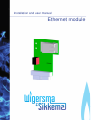
Ethernet module
3 Status indicators and connections
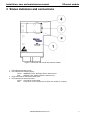
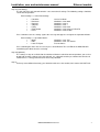
Figure 2. Connector and LED on the Ethernet module
1. LED indicator for powered on
2. LED indicator for network activity:
Green: 100BASE-TX link, blinking indicates data transfer.
Red:
10BASE-T link, blinking indicates data transfer.
3. RJ45 connector for connection to Ethernet
4. LED indicator for connected status:
Green: Constant on if connected.
Red:
Fault, blinks if an IP fault occurs or when the module is resetting.
DDNN004MHGB/09-2015/Rev.1
4