1
User Manual
Installation guide
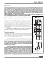
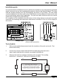
It is essential that the GCM Earth Continuity Monitor be installed in such a way that the generated
signal must travel via the fully insulated pilot conductor direct to the Remote Module. The latter
must be situated remotely from the GCM Monitor as shown in Fig.6 below. The main earth
conductor must form the return path to the GCM Monitor via the equipment frame at each end
and at intermediate points where applicable. The pilot and earth conductors plus the remote
module thus comprise the monitored loop.
On completion of the installation and connection of the wireing harness to the pilot and earth
conductors the following tests should be made before connection to the 110 volt ac supply to
the monitor.
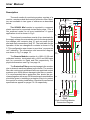
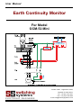
Fig 6
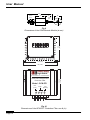
GCM-52 Mini connection
Test schedule
1.
With remote module disconnected check the insulation of the pilot and earth . Test
should read infinity.
2.
Connect the remote module with the M12 bolt fastened to the load centre
frame (earth) and the pilot conductor connected to the M8 bolt.
3.
Measure the total loop resistance between pilot and earth. This reading
should be a minimum of 100W and a maximum of 150W.
Pilot
R pilot
Black
Remote
Module
100W
R total
M8
R total = R pilot + R earth + R module
The resistance displayed by the Monitor will be :
R display = (R total - R module) = (R total -100)
Thus the Monitor only displays the resistance of
the pilot conductor plus the earth conductor.
M12
Green
R earth
Earth
GCM-52 Mini
Page 11