1
User Manual
Introduction
Earth leakage relays perform two main functions on mining installations: to protect machinery
from damage and to make the installation safer for personnel. In the typical distribution circuit
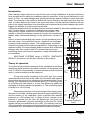
shown in Fig 1, an earth leakage relay provides protection against leakage to earth and earth
faults. The principle of this method is that all the current flowing to the load must return from the
load. If current leaks to the frame of the motor and returns via the earth bond back to the star
point of the supply transformer then this difference is detected by the earth leakage relay which
triggers the breaker, thus disconnecting the load.
It becomes apparent that the earthing must be solid and reliable for electrical installations to be
safe. For this reason, machinery is earthed via the supply cable,
using either a copper conductor of the cable or the armour. The
Supply
ground on which the machinery stands is normally not considered a
Transformer
reliable earth. Mechanical damage to the earth bond, corrosion of
the
Main Earth
armour or bad workmanship may result in a high resistance point in
the earth return. If an earth fault occurs, voltage will be developed
Neutral
Earthing
across the high resistance region. This voltage poses a potential
Resistor
hazard to any personel who may be exposed to it. Depending on the
resistance value, the current flowing and the reaction time of the earth Bus
Bars
leakage relay, this could be fatal. It is obvious that continuous
monitoring of the earth bond is imperative if safety standards are to
be maintained.
Q1
Breaker
I>
I>
E
Theory of operation
To continuously monitor the resistance of the earth bond, an electrical
measuring signal is fed into the earth conductor via a separate pilot
wire. To cater for the possibility of a short between this pilot and the
earth, a remote module must be employed.
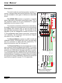
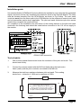
A loop now exists, consisting of the pilot wire, the remote
module and the earth wire in the cable. An intrinsically safe signal is
injected into the loop and, by interpreting the voltage and the current
flowing, the resistance can be monitored: see Fig 2. The energy level
of an intrinsically safe signal is so low that dangerous gases like
hydrogen or methane cannot be ignited by it. The monitoring signal
is limited to 5 Vdc at 50mA.
Depending on factors such as the length of the supply cable,
the nature of the load, variable speed drives or heavy load switching,
and the location of the installation, [near a pipeline with cathodic
protection or a DC railway line], a range of noise signals can be
induced or injected into the loop: the signals can vary from high
frequency generated by thyristor switching, to 50Hz and DC. Noise
signals can have an amplitude of up to 100V. The relatively low level
of the intrinsically safe measuring signal and the high electrical noise
necessitated the development of specialised measuring circuitry.
GCM-52 Mini
I>
L
Earth
Leakage
K1
Contactor
with
Overload
Cable
Earth
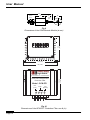
SWITCHING SYSTEMS' range of EARTH CONTINUITY
RELAYS provides a cost effective solution to the problem.
Load
Main
Earth
Fig1
A typical distribution
circuit
Page 3