1
Desoldering Tool
Instruction Manual
●
Thank you for purchasing the HAKKO FR-400 Desoldering Tool.
Please read this manual before operating the HAKKO FR-400.
Keep this manual readily accessible for reference.
●
Table of Contents
1. PACKING LIST AND PART NAMES ...................... 1
2. SPECIFICATIONS ................................................. 1
3. WARNINGS, CAUTIONS AND NOTES ................. 2
4. INITIAL SETUP ...................................................... 3
5. OPERATION .......................................................... 5
6. PARAMETER SETTING ...................................... 13
7. MAINTENANCE .................................................. 22
8. CHECKING PROCEDURE ................................. 27
9. ERROR MESSAGE ............................................. 29
10. TROUBLE SHOOTING GUIDE ......................... 30
11. PARTS LIST ...................................................... 31
12. WIRING DIAGRAM ........................................... 34
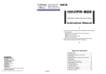
1. PACKING LIST AND PART NAMES
HAKKO FR-400 Desoldering station
HAKKO FR-4001 Desoldering Handpiece
(with ø1.0mm [0.04 in] nozzle)
Power cord
1
1
1
Please check to make sure that all items
listed below are included in the package.
Handpiece holder (with Cleaning wire)
Toolbox
Instruction Manual
1
1
1
Nozzle
(N60 series)
HAKKO
FR-4001
Handpiece holder
HAKKO FR-400
Station
Power cord
Toolbox
×1
×4
Ceramic paper Filter
(Desoldering handpiece)
×2
Station
Filter
×1
Cleaning Pin (for ø1.0mm
[0.04 in] nozzle)
Cleaning Drill (for ø1.0mm
[0.04 in] nozzle)
×1
×1
Cleaning Pin
(for Heating Element)
Nozzle wrench
2. SPECIFICATIONS
● HAKKO FR-400
Power consumption
Temperature range
Temperature stability
320W
350 - 500℃ (660 - 940℉ )
± 5℃ (9℉ ) at idle temperature
● Station
Output
Dimensions
AC 29V
160(W) × 137(H) × 235(D) mm
(6.3 × 5.4 × 9.3 in.)
Weight
5.7 kg (12.6 lb.)
Vacuum generator
Vacuum pump, double cylinder type
Vacuum pressure (max.) 80 kPa (600 mmHg)
Suction flow
15ℓ/min.
1
● HAKKO FR-4001
Part name
Power consumption
Nozzle to ground resistance
Nozzle to ground potential
Length (w/o cord)
Weight (w/o cord)
Cord
HAKKO FR-4001
300W(29 V)
<2Ω
< 2 mV
183 mm (7.2 in.) with ø1.0mm [0.04 in] nozzle
245 g (0.54 lb.) with ø1.0mm [0.04 in] nozzle
1.2 m (4 ft.)
* The temperature was measured using the HAKKO FG-101
Station Tester.
* This product is protected against electrostatic discharge.
* Specifications and design are subject to change without notice.
3. WARNINGS, CAUTIONS AND NOTES
Warnings, cautions and notes are placed at critical points in this manual to direct the
operator’s attention to significant items. They are defined as follows:
WARNING:Failure to comply with a WARNING may result in serious injury or death.
CAUTION :Failure to comply with a CAUTION may result in injury to the operator,
or damage to the items involved.
NOTE:A NOTE indicates a procedure or point that is important to the process
being described.
WARNING
When power is ON, the nozzle will be hot. To avoid injury or damage to
personnel and items in the work area, observe the following:
● Do not touch the nozzle or the metal parts near the nozzle.
● Do not allow the nozzle to come close to, or touch, flammable materials.
● Inform others in the area that the unit is hot and should not be touched.
● Turn the power off when not in use, or left unattended.
● Turn the power off when connecting the HAKKO FR-4001 or
storing the HAKKO FM-400.
● The unit is for a counter or workbench use only.
● This appliance is not intended for use by persons (including
children) with reduced physical, sensory or mental capabilities,
or lack of experience and knowledge, unless they have been
given supervision or instruction concerning use of the appliance
by a person responsible for their safety.
● Children should be supervised to ensure that they do not play
with the appliance.
To prevent accidents or damage to the HAKKO FR-400, be sure to observe the following:
CAUTION
● Do not use the unit for applications other than desoldering.
● Do not strike the handpiece against hard objects to remove excess solder. This will
damage the handpiece.
● Do not modify the HAKKO FR-400.
● Use only genuine HAKKO replacement parts.
● Do not allow the HAKKO FR-400 to become wet, or use it when hands are wet.
● Be sure to hold the plug when inserting or removing the handpiece and power cords.
● Be sure the work area is well ventilated. Soldering produces smoke.
● Be sure the cooling fan at the rear of the station is unrestricted.
● While using the HAKKO FR-400, don't do anything which may cause bodily harm
or physical damage.
2
4. INITIAL SETUP
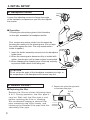
A. Handpiece holder
Loosen the adjusting screws to change the angle
of the handpiece receptacle as you like, then tighten
the screws.
● Operation
Following the instructions given in the illustration
on the right, assemble the handpiece holder.
First, remove any excess solder from the nozzle by
thrusting the nozzle into the cleaning wire. (Do not wipe
the nozzle against the wire. This may cause molten
solder to spatter.)
1. Insert the holder assembly securely into the handpiece
holder base.
2. When the cleaning wire becomes dirty or loaded with
solder, turn the wire until a clean surface is presented.
3. When changing the cleaning wire, lift the top vertically
to prevent solder debris from falling out.
CAUTION
Do not set up the angle of the handpiece receptacle too high, or
the temperature of the handpiece will become very hot.
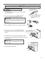
B. HAKKO FR-4001
● Replacing the filter
Replace the filter as shown following steps
A to C. During operation, the filter pipe is
very hot. Wait until the filter pipe is cool
before replacing the filter or cleaning.
We recommend keeping a second filter
pipe containing new filters handy, and
replacing the installed filter pipe with this
secondary filter pipe.
3
C. Replace the entire filter pipe with
a secondary filter pipe.
B. Pull
A. Down
CAUTION
Be sure to hold the plug when inserting or removing the handpiece cord.
C. Station
Insert the plug into
the receptacle until
it seats.
● Connection
1. Connect the power cord to the receptacle on the
rear of the station.
To disconnect, pull the plug
from the receptacle while
pressing down the tab on
the plug.
2. Connect the plug from the HAKKO FR-4001
to the receptacle on the HAKKO FR-400.
CAUTION
Connect the plug to the receptacle, aligning
the tab on the plug with the opening on the
receptacle.
3. Set the HAKKO FR-4001 in the handpiece holder.
4. Connect the hose from the HAKKO FR-4001
to the filter case cover on the HAKKO FR-400
station.
Connect the hose.
5. Plug the power cord into a grounded power outlet.
Ensure that the power switch is OFF before inserting
the AC plug.
CAUTION
Be sure to ground this product as it is ESD
safe by design.
Turn the power
switch ON
6. Turn the power switch ON.
4
5. OPERATION
PART NAMES
Normal display screen
Control
Button
C
Filter Case
Cover
Power Switch
Receptacle
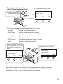
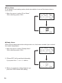
Making Changes to Settings
● Selecting the preset number
1. Press any of the
three control buttons.
3. Make your PRESENT SELECTION
by moving the cursor UP or DOWN
by pressing the corresponding
buttons.
PRESET1
PRESET2
PRESET3
<↑>
<↓>
350℃
400℃
450℃
<OK>
2. The preset selection screen
appears.
PRESET1
PRESET2
PRESET3
<↑>
<↓>
350℃
400℃
450℃
<OK>
If you wish to exit the
PRESET SELECTION
screen, simply use the
DOWN button to scroll
to the bottom of the list,
and select <EXIT>.
4. Press the “OK” button to
finalize your selection.
PRESET1
PRESET2
PRESET3
<↑>
<↓>
350℃
400℃
450℃
<OK>
If you wish to exit the PRESET SELECTION screen...
• You select <EXIT> and press the <OK> button, you will return to the normal display
without making change.
• if the device is left alone without making any operation for 10 seconds, you will return
to the normal display.
5
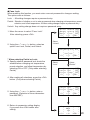
● Changing various settings
(other than preset selections)
1. Press and hold any one
of the three control buttons
for at least 2 seconds.
2. The setting selection screen
appears.
Set Temp
Offset Temp
Vacuum Check
<↑>
<↓>
<OK>
The following settings can be changed from this screen:
Set Temp
Offset Temp
Vacuum Check
Preset Temp
Preset ID
LCD Contrast
<Exit>
(Nozzle temperature setting)
(Nozzle temperature offset setting)
(Check of nozzle clogging and suction force)
(Setting of each preset temperature)
(Setting of each preset name)
(Contrast adjustment of display screen)
(Return to the setting screen)
3. Make your PRESENT SELECTION
by moving the cursor UP or DOWN
by pressing the corresponding
buttons.
Set Temp
Offset Temp
Vacuum Check
<↑>
<↓>
<OK>
4. Press the “OK” button to
finalize your selection.
Set Temp
Offset Temp
Vacuum Check
<↑>
<↓>
<OK>
* Change of selected setting
Depending on selected setting, the display on the screen differs. However, you
can make changes to the settings by following the above operation procedure.
After completing the changes to the setting, if you press the “OK” button again in
the selection screen, you will return to the normal display.
6
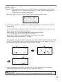
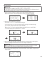
● Set Temp
CAUTION
The temperature range is from 350 to 500℃. ( 660 to 940℉)
● If you enter a value outside the temperature setting range, the display returns to
the hundreds digit, and you have to enter a correct value.
1. Move the cursor to select “Set Temp”. After selecting, press <OK>.
S e t Temp
350゚ C
O f f s e t T e m p 00゚ C
Vacuum Check
<↑>
<↓>
<OK>
2. Entering from hundreds to units digit
Press the <↑> or <↓> to set the desired figure.
Only values from 3 to 5 can be selected when entering the hundreds digit.
(In ℉ mode, values from 6 to 9 can be selected.)
Values from 0 to 9 can be selected when entering the tens or units digits.
(The same values can be selected in ℉ mode.)
C
<↑>
<↓>
<OK>
C
<↑>
<↓>
<OK>
C
<↑>
<↓>
<OK>
3. When desired figure is displayed, press the button to enter.
The next digit will begin to flash. After entering the units digit, press the button to
save the figure to the system memory and begin heater control with new setting
temperature.
CAUTION
If power is switched off or lost during the execution of this procedure, no data
will be entered. The entire procedure must be repeated from step 1.
7
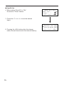
● Offset Temp
Example:If the measured temperature is 405℃ and set temperature is 400℃, the
difference is -5℃. (need to decrease by 5℃) So, enter the figure which 5
is deducted from present offset value.
1. Move the cursor to select “Offset Temp”. After selecting, press <OK>.
S e t Temp
350゚ C
O f f s e t T e m p 00゚ C
Vacuum Check
<↑>
<↓>
<OK>
2. Enter the offset value (-5) which is the difference between tip temperature and set
temperature.
The hundreds digit can display 0 (for positive value) or minus sign. (for negative value)
(Same values can be selected in ℉ mode.)
Values from 0 to 5 can be selected when entering the ten digit.
(In ℉ mode, values from 0 to 9 can be selected.)
Values from 0 to 9 can be selected when entering the units digit.
(Same values can be selected in ℉ mode.)
The allowable ranges for offset values are from -50 to +50℃ . (In ℉ mode, from -90
to +90℉) If you enter a value outside the offset value range, the display returns to
the hundreds digit, and you have to enter a correct value.
C
<↑>
<↓>
<OK>
C
<↑>
<↓>
<OK>
C
<↑>
<↓>
<OK>
3. After entering the units digit, press the button to save the figure to the system
memory and begin heater control with the new offset value.
CAUTION
During the offset setting, please be careful tip temperature does not exceed 500 ℃.
8
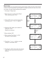
● Vacuum Check
During suction, the gauge indicating sucking status is shown at the lower side
of the screen.
C
CHK
Suction gauge
Sign of clogging
When “CHK” appears and you notice that the sucking force is weakening,
perform “Vacuum Check.”
1. Move the cursor to select “Vacuum Check”. After selecting, press <OK>.
S e t Temp
350゚ C
O f f s e t T e m p 00゚ C
Vacuum Check
<↑>
<↓>
<OK>
2. Pull the trigger.
Vacuum Check
Pu l l Tr i gge r
<EX I T>
3. When “Clogging” appears, perform cleaning and replace filters.
No degradation in sucking force
Vacuum Check
Pu l l Tr i gge r
O
K
<EX I T>
9
Degradation in sucking force
Vacuum Check
Pu l l Tr i gge r
C l ogg i ng
<EX I T>
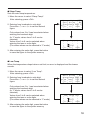
● Preset Temp
CAUTION
The temperature range is from 350 to 500℃. ( 660 to 940℉)
● If you enter a value outside the temperature setting range, the display returns to
the hundreds digit, and you have to enter a correct value.
1. Move the cursor to select “Preset Temp”. After selecting, press <OK>.
Select the preset No. whose temperature setting you wish to change.
Select the preset No.
O f f s e t T e m p 00゚ C
Vacuum Check
P r e s e t Temp
<↑>
<↓>
<OK>
P1 Temp
P2 Temp
P3 Temp
<↑>
<↓>
350゚ C
400゚ C
450゚ C
<OK>
2. Entering from hundreds to units digit
Press the <↑> or <↓> to set the desired figure.
Only values from 3 to 5 can be selected when entering the hundreds digit.
(In ℉ mode, values from 6 to 9 can be selected.)
Values from 0 to 9 can be selected when entering the tens or units digits.
(The same values can be selected in ℉ mode.)
PRESET1 TempS e t
<↑>
50゚ C
<↓>
<OK>
PRESET1 TempS e t
<↑>
3 0゚ C
<↓>
<OK>
PRESET1 TempS e t
<↑>
35 ゚ C
<↓>
<OK>
3. After entering the units digit, press the button to save the figure to the system
memory and begin heater control with new setting temperature.
CAUTION
If power is switched off or lost during the execution of this procedure, no data
will be entered. The entire procedure must be repeated from step 1.
4. To exit from each setting screen, scroll the screen, select <Exit>, and press the
<OK> button.
P2 Temp
P3 Temp
<EX I T>
<↑>
<↓>
400゚ C
450゚ C
<OK>
10
● Preset ID
CAUTION
As a preset ID, 1 to 8 characters can be used.
Usable characters are “A-Z,” “0-9,” and space (“ ”). Entering a space makes your
entry terminated. Any character(s) that follows the space is deleted.
1. Move the cursor to select “Preset ID”. After selecting, press <OK>.
Vacuum Check
P r e s e t Temp
Prese t ID
<↑>
<↓>
<OK>
2. Move up and down the cursor with the control buttons.
After selecting, press <OK>.
P1 I D
PRESET1
P2 I D
PRESET2
P3 I D
PRESET3
<↑>
<↓>
<OK>
3. Press the <↑> or <↓> to set the desired letters.
P1
ID
<↑>
SET
RESET1
<↓>
<OK>
4. To exit from setting screen, scroll the screen, select <Exit>, and press the
<OK> button.
P2 I D
PRESET2
P3 I D
PRESET3
<EX I T>
<↑>
<↓>
<OK>
11
● LCD Contrast
To make the screen display easy to see, adjust contrast.
1. Move the cursor to select “LCD Contrast”. After selecting, press <OK>.
P r e s e t Temp
Prese t ID
LCD C o n t r a s t
<↑>
<↓>
<OK>
2. Press the <↑> or <↓> to set the adjust contrast.
(Selection range is 1 to 25.)
LCD C o n t r a s t
A d j u s t me n t
10
<↑>
<↓>
<OK>
3. Press the <OK> button to set the value.
To exit from each setting screen, scroll the screen, select <Exit>, and press
the <OK> button.
Prese t ID
LCD C o n t r a s t
<EX I T>
<↑>
<↓>
<OK>
12
6. PARAMETER SETTING
● PARAMETER SETTINGS
Press and hold any one of the three control buttons, and turn on the power switch to
display the parameter setting screen. The following parameters can be set:
Value
Initial value
Press and hold any one of
the three control buttons while
℃/℉
℃ (℉*)
turning on the power switch.
OFF / ON
OFF
30 ~ 60 min
30 min
Normal / Timer
Normal
①
1∼5sec
1sec
OFF / 1 ~ 29min
6 min
200 ~ 300℃
200℃ (390℉)
(390 ~ 570 ℉)
②
30 ~ 150℃ (54 ~ 270℉)
150℃ (270℉)
Low Temp
ON / OFF
ON
Error Alarm
ON / OFF
ON
Ready Alarm
Pass. Lock
ON (Lock/Partial) / OFF (unlock) OFF
Password**** “ABCDEF” Select three letters Initial Reset
℃ / ℉ / Cancel
* For USA.
** Auto-shutOff Time can be set when Auto-ShutOff is set to ON.
*** Vacuum Time is displayed when Vacuum Mode is set to "Timer."
****Password is displayed when Password Lock is set to "ON" or "Partial."
Parameter name
Temp Mode
ShutOff Set
Timer**
Vaccum Mode
Vacuum Time***
AutoSleep
Sleep Temp
* Operation procedure for parameter setting
Use <↑>, <↓>, and <OK> to set parameters as you do in the operation settings. When you are finished,
press the “OK” button in the parameter setting screen to return to the normal display.
13
● Temp Mode
The displayed temperature can be switched between Celsius and Fahrenheit.
1. Move the cursor to select “Temp Mode”.
Temp Mo d e
After selecting, press <OK>.
゚C
S h u t O f f S e t OFF
V a c u u m M o d e NOR
<↑>
<↓>
<OK>
2. ℃ and ℉ will be switched alternately
if you press the <↑> or <↓> button.
Temp Mo d e
3. Return to parameter setting display
if you press the <OK> button after
setting.
<↑>
゚F
<↓>
Se t
<OK>
● ShutOff Set
Select whether you will activate the auto shut off function. When the auto shutoff
function is set to on and no operation is performed for constant time after the iron is
set in the iron holder, the buzzer sounds three times and the auto shutoff function
will be enabled.
Temp Mo d e
゚C
S h u t O f f S e t OFF
V a c u u m M o d e NOR
<↑>
<↓>
<OK>
1. Move the cursor to select “ShutOff Set”.
After selecting, press <OK>.
2. ON and OFF will be switched alternately
if you press the <↑> or <↓> button.
3. Selecting “ON” allows you to make the
setting for “Timer.”
(Default is 30 minutes.)
Select
“OFF”
Shu t Of f
Shu t Of f
T i me r
<↑>
<↓>
Se t
OFF
30m
<OK>
Select
“ON”
(Next page)
14
● ShutOff Set
4. When setting “Shut Off” to “ON,”
the area for “Timer” flashes.
Shu t Of f
Shu t Of f
T i me r
<↑>
<↓>
Se t
ON
0m
<OK>
5. Press the <↑> or <↓> to set the desired
figure.
6. Pressing the <OK> button after this change
makes the set time stored in the internal memory.
15
Temp Mo d e
゚C
S h u t O f f S e t OFF
V a c u u m M o d e NOR
<↑>
<↓>
<OK>
● Vacuum Mode
Select whether you manually operate the desoldering pump or use the timer function.
Normal:Solder is sucked only when you are pulling the trigger.
Timer:Even after you release the trigger, sucking continues for the specified period of time.
* Set time in “Vacuum Time.”
1. Move the cursor to select “VacuumMode”.
After selecting, press <OK>.
2. Normal and Timer will be switched alternately
if you press the <↑> or <↓> button.
Temp Mo d e
゚C
S h u t O f f S e t OFF
V a c u u mM o d e
NOR
<↑>
<↓>
<OK>
Select
“Normal”
V a c u u m Mo d e
<↑>
T i me r
<↓>
3. Return to parameter setting display
if you press the <OK> button after
setting.
Se t
<OK>
Select
“Timer”
(Vacuum Time)
* When selecting Timer:
“Vacuum Time” appears under “Vacuum Mode” in the parameter select screen.
● Vacuum Time
1. Move the cursor to select “Vacuum Time”.
After selecting, press <OK>.
S h u t O f f S e t OFF
V a c u u mM o d e T I M E
V a c u um T i me
1s
<↑>
<↓>
<OK>
2. Press the <↑> or <↓> button, you can
change to the desired value.
V a c u u m T i me S e t
0
3. Return to parameter setting display
if you press the <OK> button after
setting.
<↑>
sec
<↓>
<OK>
16
● Auto Sleep
Select whether you will activate the auto sleep function. When the auto sleep function
is set to on and no operation is performed for constant time after the iron is set in the
iron holder, the auto sleep function will be enabled.
* Set temp in “Sleep temp”.
1. Move the cursor to select “Auto Sleep”.
After selecting, press <OK>.
2. ON and OFF will be switched alternately
if you press the <↑> or <↓> button.
3. Selecting “ON” allows you to make the
setting for “Timer.”
(Default is 6 minutes.)
S h u t O f f S e t OFF
V a c u u mM o d e
NOR
Au t o S l e e p
OFF
<↑>
<↓>
<OK>
Select
“OFF”
Au t o S l e e p S e t
Au t o S l e e p
OFF
T i me r
06m
<↑>
<↓>
<OK>
Select
“ON”
* When selecting “ON”
4. When setting “Auto Sleep” to “ON,”
the area for Timer flashes.
Au t o S l e e p S e t
Au t o S l e e p
ON
6m
T i me r
<↑>
<↓>
<OK>
5. Press the <↑> or <↓> button, you can
change to the desired value.
6. Pressing the <OK> button after this change
makes the set time stored in the internal
memory.
17
S h u t O f f S e t OFF
V a c u u mM o d e
NOR
Au t o S l e e p
6m
<↑>
<↓>
<OK>
● Sleep Temp
Sets the auto sleep temperature.
1. Move the cursor to select “Sleep Temp”.
After selecting, press <OK>.
2. Entering from hundreds to units digit.
Press the <↑> or <↓> to set the desired
figure.
Only values from 2 to 3 can be selected when
entering the hundreds digit.
(In ℉ mode, values from 3 to 5 can be
selected.)
Values from 0 to 9 can be selected when
entering the tens or units digits.
(The same values can be selected in ℉ mode.)
V a c u u mM o d e
NOR
Au t o S l e e p
6m
S l e e p T e m p 200゚ C
<↑>
<↓>
<OK>
S l e ep
<↑>
Temp
00゚ C
<↓>
Se t
<OK>
3. After entering the units digit, press the button
to save the figure to the system memory
● Low Temp
When the temperature drops below a set limit, an error is displayed and the buzzer
sounds.
1. Move the cursor to select “Low Temp”.
After selecting, press <OK>.
2. Entering from hundreds to units digit.
Press the <↑> or <↓> to set the desired
figure.
Only values from 0 to 1 can be selected when
entering the hundreds digit.
(In ℉ mode, values from 0 to 2 can be
selected.)
Values from 0 to 9 can be selected when
entering the tens or units digits.
(The same values can be selected in ℉ mode.)
Au t o S l e e p
6m
S l e e p T e m p 200゚ C
L o w Te m p
150゚ C
<↑>
<↓>
<OK>
L ow
<↑>
Temp
Se t
50゚ C
<↓>
<OK>
3. After entering the units digit, press the button
to save the figure to the system memory
18
● Error Alarm
In the buzzer sound setting mode, which sets whether to sound the buzzer when a
error occurs.
1. Move the cursor to select “Error Alarm”.
After selecting, press <OK>.
S l e e p T e m p 200゚ C
L o w Te m p
150゚ C
E r r o r A l a r m ON
<↑>
<↓>
<OK>
Er r or
<↑>
A l arm
Se t
OFF
<↓>
<OK>
● Ready Alarm
When the set temperature alert setting mode is on, the buzzer sounds if you reached
the usable temperature.
1. Move the cursor to select “Ready Alarm”.
After selecting, press <OK>.
L o w Te m p
150゚ C
E r r o r A l a r m OFF
R e a d y A l a r m ON
<↑>
<↓>
<OK>
2. ON and OFF will be switched alternately
if you press the <↑> or <↓> button.
3. Return to parameter setting display if you
press the <OK> button after setting.
19
Re a d y A l a r m S e t
O N
OFF
<↑>
<↓>
<OK>
● Pass. Lock
When enabling this function, you must enter a correct password to change a setting.
The options are as follows:
Lock : All setting changes require a password entry.
Partial : Selection of whether or not to enter a password when changing set temperature, preset
selection, and offset temperature. All other setting changes require a password entry.
Unlock:Any setting change does not require a password entry.
E r r o r A l a r m OFF
R e a d y A l a r m OFF
Pa s s . L o c k
OFF
<↑>
<↓>
<OK>
1. Move the cursor to select “Pass. Lock”.
After selecting, press <OK>.
2. Using the <↑> or <↓> button, select an
option from Lock, Partial, and Unlock.
Select
“Unlock”
Pa s s wo r d L o c k S e t
<↑>
* When selecting Partial or Lock:
3. Specify whether password lock should be
enabled when changing set temperature,
preset selection, and offset temperature by
selecting ON or OFF. (Only when selecting
Partial)
UnL o c k
<↓>
<OK>
Select
“Lock”
Select
“Partial”
S e t Temp
OFF
P r e s e t Se l
OFF
O f f s e t Temp
OFF
<↑>
<↓>
<OK>
4. After making all selections, press the <OK>
button. (Only when selecting Partial)
5. Using the <↑> or <↓> button, enter a
password. (Selection of three characters
from ABCDEF)
6. Return to parameter setting display
if you press the <OK> button after
setting.
Prese t
Of f se t
<↑>
Se l
OFF
Temp
OFF
OK
<↓>
<OK>
Pa s s wo r d
***
OK
<↑>
<↓>
Se t
<OK>
20
● Initial Reset
Initial Reset allows the factory default settings to be restored.
1. Move the cursor to select “Initial Reset”.
After selecting, press <OK>.
2. Using the <↑> or <↓> button, select
either C or F. To stop Initial Reset, scroll
the screen to select <Exit>.
3. After selecting it, using the <↑> or <↓>
button, select OK or Cancel.
R e a d y A l a r m OFF
Pa s s . L o c k
OFF
I n i t i a l Re se t
<↑>
<↓>
<OK>
I n i t i al
Re se t
゚ F
<↓>
<OK>
<↑>
I n i t i a l Re se t
゚C
<↑>
<↓>
<OK>
CAUTION
Even when Initial Reset is finished, “Pass. Lock” and password settings remain.
After completing settings, if you press the “OK” button again in the selection
screen, you will return to the normal display.
Pa s s . L o c k
OFF
I n i t i a l Re se t
<EX I T>
<↑>
<↓>
<OK>
21
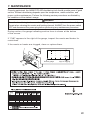
7. MAINTENANCE
Properly maintained, the HAKKO FR-400 desoldering tool should provide years of good
service. Efficient desoldering depends upon the temperature, nozzle selection, and
proper routine maintenance. Perform the following service procedures as dictated by
the conditions of the station's usage.
WARNING
Since the desoldering tool can reach a very high temperature, please work carefully.
Except when cleaning the nozzle and heating element, ALWAYS turn the power switch
OFF and disconnect the power plug before performing any maintenance procedure.
During suction, the gauge indicating suction force is shown at the bottom
of the screen.
If "CHK" appears to the right of the gauge, inspect the nozzle and heater for
restrictions.
If the nozzle or heater are clogged, clean or replace them.
C
CHK
Suction gauge
連接部
隔離器
電路板
插座
電磁蓋
真空泵組件
螺釘
坦克組件
排出閥門
×
×
×
×
×
×
×
×
×
○
○
○
○
○
○
○
○
○
○
○
○
○
○
○
○
○
○
○
○
○
○
○
○
○
○
○
○
○
○
○
○
○
○
○
○
Sign of clogging
○
○
○
○
○
○
○
○
○
22
Nozzle Maintenance
CAUTION
The desoldering tool may be extremely hot. During maintenance, please work carefully.
1. Inspect and clean the nozzle
● Turn the power switch ON and let the nozzle
heat up.
Cleaning with the nozzle cleaning pin
The cleaning pin passes
completely through the
hole.
CAUTION
The cleaning pin will not pass through the
nozzle until the solder inside the nozzle is
completely melted.
● Clean out the hole of the nozzle with the
nozzle cleaning pin.
● If the cleaning pin does not pass through the
hole in the nozzle, clean with the cleaning
drill.
Cleaning with the cleaning drill
● Before cleaning
Insert the bit while turning it
clockwise.
● After cleaning
● Check the condition of the solder plating on
the nozzle tip.
CAUTION
If the cleaning drill is forced into the nozzle, the drill bit
could break or be damaged.
Please use the proper size cleaning pin or cleaning drill
for the nozzle diameter.
Pull the drill bit out straight
without turning it.
Use the proper size cleaning
pin or cleaning drill for the
nozzle diameter.
● Check visually if the nozzle was eroded.
• If the cleaning pin and cleaning drill do not pass through the hole
in the nozzle, replace the nozzle.
• If the solder plating on the nozzle tip is worn, replace the nozzle.
• If the inside hole of the nozzle is eroded, replace the nozzle.
Hole is damaged by erosion.
CAUTION
Desoldering efficiency goes down and all other parts appear to be OK, the nozzle is
probably eroded and should be replaced.
The inside hole and the surface of the nozzle is plated with a special alloy. Should
this alloy become eroded by high temperature solder, the nozzle will not be able to
maintain the proper temperature.
● If the nozzle is still in a good condition, put some fresh solder on the nozzle tip to
protect solder plated area from oxidation.
23
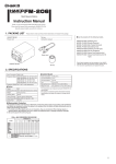
2. Disassemble the heating element.
CAUTION
The heating element is very hot during operation.
Element Cover
Heating Element
Nozzle
Nut
Remove the element cover assembly and the nozzle with the attached wrench.
3. Clean out the tube in the heating element
with the provided cleaning pin.
Scrape away all oxidation from the tube
in the heating element until the cleaning
pin passes cleanly through the tube.
● Turn the power off after cleaning.
CAUTION
・Be sure the solder in the tube in the heating element is completely heated, before
cleaning the tube.
・If the cleaning pin does not pass through the tube in the heating element, replace
the heating element.
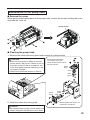
4. Replace the filters.
● When the filter pipe is cool to the touch, push down on the release knob at the back
of the handpiece and remove the filter pipe.
CAUTION
The filter pipe is very hot.
● Examine the seals (front and back holders) at each end of the filter pipe.
Replace : Stiff and/or cracked.
● Examine the Pre-filter: Remove solder adhering to the waste collector.
● Examine the ceramic paper filter.
Replace : Ceramic paper filter is showing signs of stains from flux, is stiff,
or contains any solder.
Front holder
Back holder
Ceramic paper
filter
FRONT
Pre-filter
5. Replacement of station filter
If the filer is showing signs of stains
from flux or is stiff, replace it.
Attach the filter as shown in the right
diagram.
①
②
Filter
Filter case cover
Filter case cover
(with Filter)
24
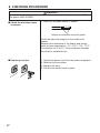
Replacing the heating element (heating core)
CAUTION
Except the case especially indicated, always turn the power switch OFF and disconnect the
power plug before performing any maintenance procedure.
● Disassemble the heating element.
1. Remove the nozzle and element cover assembly.
Heating
Element
Element
Cover
Nozzle
Nut
Remove the element cover assembly and the nozzle with the attached wrench.
2. Remove the 3 screws from the handpiece and disconnect the heating element.
Heating
Element
3. Replace the heating element. Assemble using the same procedure in reverse.
CAUTION
Be sure to calibrate the nozzle temperature after replacing the heating element. Failure to do
this may result in a heater temperature that is much higher or lower than the previous one.
25
Maintenance of the pump head
● Remove the cover
When performing maintenance on the pump head, remove the screws holding the cover
and take the cover off.
pump head
● Cleaning the pump head
1. Remove the valve and valve guard and remove any attached flux.
CAUTION
• When the valve guard is difficult to remove,
please warm it with hot air. Please do not try
to forcibly remove it with a screwdriver, etc.
If the valve guard becomes deformed, it will
no longer be airtight.
• Please clean with either alcohol or thinner.
Pump head disassembly
*It is resting on its side.
Clean the pump head, valve
and valve guard.
Pump
head
Valve
Valve
guard
Pump
head
2. Install the valve and valve guard.
Caution
When assembling the pump, please make sure
to keep it airtight so that there are no air leaks.
Valve
guard
Valve
*Please replace the valve if it is
deformed or hardened.
26
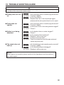
8. CHECKING PROCEDURE
WARNING
Unless otherwise directed, carry out these procedures with the power switch OFF and
the power UNPLUGGED.
■ Check for a broken heater
or sensor
1. Check for a broken heater or sensor
Measure the resistance across this position.
Verify the electrical integrity of the heater and
sensor.
Measure the resistance of the heater and sensor
while at room temperature(15∼25℃;59∼77℉).
It should be 3.4 Ω ±10%. If the resistance exceeds
these limits, replace the tip.
■ Replacing the fuse
27
1. Unplug the power cord from the power receptacle.
2. Remove the fuse holder.
3. Replace the fuse.
4. Put the fuse holder back in place.
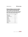
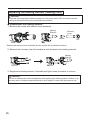
■ Checking the connection
cord for breakage
5
3
8
2
6
Socket
Checking the connection cord for breakage
1. Unplug the connection cord from the station.
4
2. Disassemble the heating element. {Please
refer to [Replacing the heating element
(heating core)]}
1
7
3. Measure the resistance values between the
connector and the lead wires at the socket as
follows:
① Red
Brown
②
Yellow
③
Switch board
⑤ Green
Black
Grounding
line
④
Purple
Pin1・・・・・・・・・・・・Red (Socket) ①
Pin2・・・・・・・・・・・・Green (Grounding line) ⑤*
Pin3・・・・・・・・・・・・Black (Switch board) ②
Pin5・・・・・・・・・・・・Yellow (Switch board) ③
Pin6・・・・・・・・・・・・Purple (Switch board) ④
Pin8・・・・・・・・・・・・Brown (Socket) ①
If any value exceeds 0 Ω or is ∞, replace the
connection cord.
* For information on the plug 2, refer to “■
Checking the grounding line”)
■ Checking the grounding
line
1. Measure the resistance value between Pin 2
and the nozzle.
2. If the value exceeds 2 Ω (at room temperature), perform the nozzle maintenance. If the
value still does not decrease, check the
connection cord for breakage.
28
9. ERROR MESSAGE
● Sens Error
When there is the possibility that a failure has occurred in the
sensor or heater (including the sensor circuit), "Sens Error" is
displayed and the power is shut down.
● Grip Error
"Grip Error" will be displayed if the connector cord is not attached
to the station OR the wrong soldering iron is connected.
● Low Temp Error
If the sensor temperature falls below the difference between the
current temperature setting and the low-temperature alarm
tolerance, "Low Temp Error" is displayed and the warning buzzer
sounds. When the nozzle temperature rises to a value within the
set tolerance, the buzzer will stop sounding.
EXAMPLE:
350℃ (400℃ - 50℃)
Set temperature
Low-temperature alarm tolerance
OR
650℉ (750℉ - 100℉)
Set temperature
Low-temperature alarm tolerance
EXAMPLE:
Assume that the temperature setting is 400℃/750℉ and the
tolerance 50℃/100℉. If the temperature continues to decrease
and finally falls below the value indicated while the heating
element is on, "Low Temp Error" is displayed.
● Heater Short Error
"Heater Short Error" will flash, and the buzzer will sound
continuously, when the nozzle is inserted incorrectly, an incompatible
nozzle is inserted, or a foreign object has found its way into the
connector.
● FATAL Error
This is displayed when the system is unable to operate normally.
Should this error be displayed, please contact your HAKKO
representative.
29
10. TROUBLE SHOOTING GUIDE
WARNING
Before checking the inside of the HAKKO FR-400 or replacing parts, be sure to disconnect the power
plug. Failure to do so may result in electric shock.
● Display does not turn
on.
CHECK
ACTION
CHECK
ACTION
:
:
:
:
Is the power supply cable or connection plug disconnected?
Connect it tightly.
Is the fuse blown?
Replace the fuse. If the fuse blows again,
please send the entire product back to us for repair.
● Pump does not
operate.
CHECK
ACTION
CHECK
ACTION
:
:
:
:
Is the power supply cable or connection plug disconnected?
Connect it tightly.
Is the nozzle or hole in the heating element clogged?
Clean it.
● Solder is not being
absorbed.
CHECK
ACTION
CHECK
ACTION
CHECK
ACTION
:
:
:
:
:
:
Is the heater tube or nozzle clogged?
Clean it.
Is the ceramic filter hardened?
Replace it with a new one.
Is there a vacuum leak?
Check the connections and filter pipe seals and
replace any worn parts.
● The nozzle does not
heat up.
CHECK
ACTION
CHECK
ACTION
:
:
:
:
Is the desoldering gun cord assembly properly connected?
Connect it tightly.
Is the heating element damaged?
Replace it with a new one.
NOTE :
When repairs are needed, please send both the handpiece and the station to
your sales agent.
30
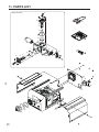
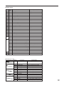
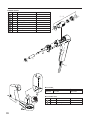
11. PARTS LIST
⑨
Pump assembly
⑦
③
⑳
②
⑤
⑪
①
⑫
21
⑬
⑩
①
③
②
⑧
⑧
⑪
22
⑫
⑤
⑥
④
⑨
⑦
⑱
⑲
⑯
⑮
⑭
31
⑰
● HAKKO FR-400
Part Name
Item No. Part No.
Specifications
1
A1013 Diaphragm
2 pcs.
2
A1014 Valve plate
2 pcs.
3
B1050 Pump head
4
B1053 Balance weight
5
B1056 Fixing plate
6
B1057 Ring for bearing
7
B1059 Exhaust filter
8
B1312 Crank
2 pcs.
9
B1313 Filter retaining pin
10
B2060 Crank shaft
11
B2085 Diaphragm setting plate
12
B2506 Damper
13
B3428 Motor
14
B5076 Vacuum outlet cap
15
A5020 Filter
16
B5077 O-ring
17
B3414 Inner hose joint
18
B2384 Inlet
19
B3674 Fuse/250V-7A
100 - 120V
B3675 Fuse/250V-4A
220 - 240V
B2419 Power cord, 3 wired cord & American plug
USA
B2421 Power cord, 3 wired cord but no plug
220-240V
B2422 Power cord, 3 wired cord & BS plug
India
B2424 Power cord, 3 wired cord & European plug
220V KTL, 230V CE
B2425 Power cord, 3 wired cord & BS plug CE
230V CE, U.K
20
2 pcs.
Set of 10
B2426 Power cord, 3 wired cord & Australian plug
B2436 Power cord, 3 wired cord & Chinese plug
China
B3508 Power cord, 3 wired cord & American plug(B)
B3550 Power cord, 3 wired cord & SI plug
21
C5011 Toolbox
22
B5082 Nozzle wrench
● Cleaning pin / Drill
Part Name
Part No.
B1215 Cleaning pin
B1086
B1087
B1088
B1089
B1302
B1303
B1304
B1305
B1306
B1307
B1308
B1309
B1310
B1311
Cleaning pin
Cleaning pin
Cleaning pin
Cleaning pin
Cleaning drill
Cleaning drill
Cleaning drill
Cleaning drill
Drill holder
Drill holder
Drill bit
Drill bit
Drill bit
Drill bit
Specifications
For heating element
For ø0.8 mm (0.03 in.) nozzle
For ø1.0 mm (0.04 in.) nozzle
For ø1.3 mm (0.05 in.) nozzle
For ø1.6 mm (0.06 in.) nozzle
For ø0.8 mm (0.03 in.) nozzle
For ø1.0 mm (0.04 in.) nozzle
For ø1.3 mm (0.05 in.) nozzle
For ø1.6 mm (0.06 in.) nozzle
For ø0.8 mm (0.03 in.)/1.0 mm (0.04 in.) nozzle
For ø1.3 mm (0.05 in.)/1.6 mm (0.06 in.) nozzle
For ø0.8 mm (0.03 in.) nozzle (set of 10)
For ø1.0 mm (0.04 in.) nozzle (set of 10)
For ø1.3 mm (0.05 in.) nozzle (set of 10)
For ø1.6 mm (0.06 in.) nozzle (set of 10)
32
● HAKKO FR-4001
Item No. Part No.
Specifications
Part Name
1
A5017
Front holder
2
B5080
Pre-filter
3
A5018
Filter holder
①∼④
4
A5019
Ceramic paper filter
1 - 4
B5081
Filter pipe assembly
5
B5078
Nut
6
B5079
Element cover
7
A5016
Heating element
8
B2877
Hose
④
③
Set of 10
②
①
⑦
⑥
⑤
⑧
● Iron Holder
Part No.
FH400-82
1
Specifications
With 599B
2
● Iron Holder Parts
Item No.
33
Part Name
Iron holder
Part No.
Part Name
1
FT400-81 Tip cleaner
2
599-029
Cleaning wire
Specifications
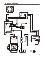
12. WIRING DIAGRAM
Inlet
Power
switch
34
HEAD OFFICE
4-5, Shiokusa 2-chome, Naniwa-ku, Osaka 556-0024 JAPAN
TEL:+81-6-6561-3225 FAX:+81-6-6561-8466
http://www.hakko.com E-mail:[email protected]
OVERSEAS AFFILIATES
U.S.A.: AMERICAN HAKKO PRODUCTS, INC.
TEL: (661) 294-0090 FAX: (661) 294-0096
Toll Free (800)88-HAKKO
4 2 5 5 6
http://www.hakkousa.com
HONG KONG: HAKKO DEVELOPMENT CO., LTD.
TEL: 2811-5588 FAX: 2590-0217
http://www.hakko.com.hk
E-mail:[email protected]
SINGAPORE: HAKKO PRODUCTS PTE LTD.
TEL: 6748-2277 FAX: 6744-0033
http://www.hakko.com.sg
E-mail:[email protected]
Please access to the following address for the other Sales affiliates.
http://www.hakko.com
Copyright © 2015 HAKKO Corporation. All Rights Reserved.
2015.5
MA02723XZ150501


![[ For FX951-51 -up ] Service Manual](http://vs1.manualzilla.com/store/data/006022140_1-0f4cb22e78fbda3a4f7c4fb90e43baab-150x150.png)