1
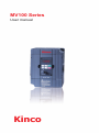
MV100 Series
User manual
Kinco
Thank you for choosing the general-purpose inverter of MV100
series of multi-functions and high performance.
Incorrect handing might cause an unexpected fault. Before using
the inverter, always read this instruction manual and the instruction
manual packed with the product carefully to use the equipment to its
optimum.
Do not attempt to install, operate, maintain or inspect the inverter
until you have read through instruction manual and appended
documents carefully and can use the equipment correctly. Do not
use the inverter until you have a full knowledge of the equipment,
safety information and instructions. In this instruction manual the
safety instruction levels are classified into “Danger” and “Warning”,
please pay special attention to the symbols “
Warning” and their relevant contents.
Danger ” and “
“ Danger” Assumes that incorrect handing may cause hazardous
conditions,resulting in death or severe injury.
“
Warning” Assumes that incorrect handing may cause hazardous
conditions, resulting in medium or slight injury, or may cause
physical damage only.
The figures in this instruction manual are for convenience with
description, they may have slight differences compared to the
product, and the product update can also cause slight differences
between the figure and product, the actual sizes are subject to
actual products.
Please read carefully the operation manual before putting the
inverter to use so as to correctly install and operate the inverter,
give full play to its functions and ensure the safety. Please keep
the operation manual handy for future reference, maintenance,
inspection and repair.
If you have any questions, please contact us or our agents in time,
you will always receive our best attention.
Operation Instruction of MV100 Series Inverter
Contents
Chapter 1 Safety Cautions.............................................................1
1-1 Confirmation on receiving
................................................1
1-2 Transportion and installation ................................................1
1-3 Wiring and Junction .............................................................3
1-4 Power-on, Test operation......................................................4
1-5 Inspection and Maintenance.................................................5
1-6 Emergency stop....................................................................6
1-7 Disposing of the inverter.......................................................6
Chapter 2 Product Introduction....................................................7
2-1 Unpacking Confirmation . .....................................................7
2-2 Inverter model description . ..................................................7
2-3 Product Specifications .........................................................8
2-4 Product storage . ..................................................................9
Chapter 3 Installation of the Inverter..........................................11
3-1 Installation environment and requirements ........................11
3-2 Inverter outline dimension drawings....................................13
Chapter 4 Wiring...........................................................................14
4-1 Main Circuit Wiring .............................................................15
4-1-1 Peripheral Devices Description ...............................15
4-1-2 Main Circuit Wiring Notice .......................................15
4-1-3 Peripheral Devices Specifications............................17
Contents‖1
Contents
4-1-4 Specification of main circuit terminal........................18
4-2 Control circuit terminal........................................................19
4-2-1 Basic wiring diagram ...............................................19
4-2-2 Control terminals layout (0.4~1.5kW).......................19
4-2-3 Control circuit terminals description.........................19
4-2-4 Wiring instructions....................................................21
Chapter 5 Operation.....................................................................22
5-1 Opeation panel....................................................................23
5-1-1 Key Function description..........................................23
5-1-2 Displays description.................................................23
5-2 Operating panel operation instruction.................................24
Chapter 6 Table of Function Parameters....................................27
Chapter 7 Detailed Explanations of Functional Parameters ...42
7-1 Parameters for monitoring...................................................42
7-2 Basic parameters................................................................46
7-3 Parameters of basic applications........................................57
7-4 Parameters for input and output application.......................63
7-5 Secondary application group...............................................80
7-6 Special operation (PLC Control).........................................90
7-7 Special operation (PID Control)..........................................97
7-8 Initial settings and specifications
of RS-485 communication.................................................104
7-9 Advanced application parameters..................................... 111
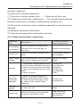
Chapter 8 Precautions for Maintenance and Inspection........114
8-1 Inspection..........................................................................114
8-1-1 Daily inspection......................................................114
Contents‖2
Operation Instruction of MV100 Series Inverter
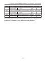
8-1-2 Periodic inspection................................................114
8-1-3 Daily and periodic inspection..................................115
8-2 Replacement of parts.......................................................116
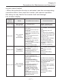
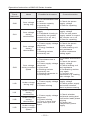
8-3 Trouble shooting................................................................116
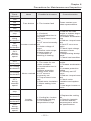
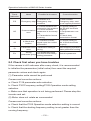
8-3 Check first when you have troubles..................................120
8-4 Inverter-generated noises
and their reduction techniques..........................................122
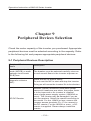
Chapter 9 ....................................................................................124
9-1 Peripheral Devices Description.........................................124
9-2 Applied Braking resistor Specification...............................125
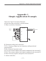
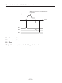
Appendix 1 Simple Application Example.................................127
Contents‖3
Chapter 1 Safety Cautions
Chapter 1 Safety Cautions
1-1 Confirmation on receiving
Warning
The inverter has been strictly and well packed before ex-work .
Inconsideration of various factors during the transportation special
attention should be paid to the following points before the assembly
and installation. If there is anything abnormal please notify the
dealer or the relevant people of our company.
• Check if the inverter has got any damage or deformation during
the transportation and handling.
• Check if there is one piece of MV100 series inverter and one copy
of the instruction manual available when unpacking it.
• Check the information on the nameplate to see if the specifications
meet your order (Operating voltage and KVA value).
• Check if there is something wrong with the inner parts, wiring and
circuit board.
• Check if each terminal is tightly locked and if there is any foreign
article inside the inverter.
• Check if the operator buttons are all right.
• Check if the optional components you ordered are contained.
• Check if there is a certificate of qualification and a warranty card.
1-2 Transportion and installation
Warning
• When carrying products, use correct lifting gear to prevent injury.
• Do not stack the inverter boxes higher than the number
·1·
Operation Instruction of MV100 Series Inverter
recommended.
• Ensure that installation position and material can withstand the
weight of the inverter. Install according to the information in the
instruction manual.
• Do not install or operate the inverter if it is damaged or has parts
missing.
• When carring the inverter, do not hold it by the front cover or
setting dial. It may fall or fail.
• Do not stand or rest heavy objects on the product.
• Check the inverter mounting orientation is correct.
• Prevent other conductive bodies such as screws and metal
fragments or other flammable substance such as oil from entering
the inverter.
• As the inverter is a precision instrument, do not drop or subject it
to impact.
• Use the inverter under the following enviromental conditions.
Otherwise, the inverter may be damaged.
Ambient temperature: -10℃~40℃ <non-freezing>.
Ambient humidity: 95% RH or less <non-condensing>
Ambient environment: indoors <free from corrosive gas,flammable
gas,oil mist,dust and dirt, free from direct sunlight>
Vibration: max. 0.5G
• Please make sure that the screws are fixed, fastened firmly in
accordance with the stipulations of the instruction manual, to
prevent the inverter falling.
• If two or more inverters are installed in a control cabinet, please
install them according to the information in the instruction manual,
and it is required to keep enough space and install extra cooling
fans to keep the air in the cabinet flowing freely to keep the
temperature inside the cabinet lower than 40℃. Overheating may
cause inverter fault, fire or other accidents.
• Due to the inverter of akind of electrical and electronic product
·2·
Chapter 1 Safety Cautions
it must be installed, tested and adjusted with parameters by
specialized engineering persons of motors.
1-3 Wiring and Junction
Warning
• Please do not damage the wires. Let the wires bear weight or be
clamped may damage the wires and cause an electric shock.
• Do not install a power factor correction capacitor or surge
suppressor/radio noise filter (capacitor type filter ) on the inverter
output side.
• Do not install switch devices such as the air switch and contactor
on the inverter output side, if it is for technologic demand, please
ensure that the inverter is switching without output.
• Wrong wiring might lead to damage of the inverter. The control
signal lines must be kept fully away from the main circuit to protect
them from noise.
Danger
• Please ensure that the power is off before junction.
• The wiring work shall be done by qualified electricians.
• Please wire the wires in accordance with the specifications
stipulated in the instruction manual.
• The grounding connection shall be done correctly and in
accordance with relative regulations in the instruction manual,
otherwise it may cause an electric shock or fire.
• Please use independent power supply for the inverter, never use
the same power supply with strong interference equipment like
electric welder.
• Please do not touch the bottom plate with wet hand, otherwise you
may get an electric shock.
• Please do not touch the terminals directly, do not connect the
·3·
Operation Instruction of MV100 Series Inverter
inverter’s input or output terminals to the inverter's shell, otherwise
you may get an electric shock.
• Please make sure that the voltage of the power supply and the
voltage of the inverter are same, otherwise it may cause the
inverter fault or personnel injury.
• The power supply cables must be connected to R,S,T. Never
connect the power cable to the U,V,W of the inverter.Doing so will
damage the inverter.
• Please do not conduct pressure resistance test to the inverter,
otherwise it may cause the inverter’s internal fault.
• Please install accessories such as brake units, brake resistors
in accordance with the regulations of the instruction manual,
otherwise it may cause the inverter fault or fire.
• Please ensure that the screws of the terminals are firmly locked,
otherwise it may cause the inverter fault.
1-4 Power-on, Test operation
Warning
• While power is on or when the inverter is running, do not open the
front cover. Otherwise you may get an electric shock.
• Do not run the inverter with the front cover or wiring cover
removed. Otherwise, you may access the exposed high-voltage
terminals or the charging part of the circuitry and get an electric
shock.
• Before starting operation , confirm and adjust the parameters. A
failure to do so may cause some machines to make unexpected
motions.
• It is recommended to undertake test runs with no load.
• Please provide an emergency stop switch when the “stop” function
setting is unavailable.
• Do not use the inverter input side magnetic contactor to start/stop
·4·
Chapter 1 Safety Cautions
the inverter, otherwise it may affect the life of the inverter.
Danger
• When fault restart function is set, please do not approach the
equipment because the equipment may automatically restart after
the running stop.
• Make sure that the specification and rating match the system
requirements. Exceeding their use range can cause motor and
machine fault.
• Please do not change the parameter settings of inverter casually
during running.
• While power is on or for some time after power-off, do not touch
the inverter as it is hot and you may get burnt.
• Perform setting dial and key operations with dry hands to prevent
an electric shock. Otherwise you may get an electric shock.
• Please do not link or withdraw motors during the inverter running,
otherwise it may cause inverter protection or fault.
1-5 Inspection and Maintenance
Warning
• Please ensure that the power supply and the power indicating light
is off before inspecting and maintaining. Otherwise you may get
an electric shock.
• For prevent damage due to static electricity,touch nearby metal
before touching this product to eliminate static electricity from your
body.
• Do not carry out a megger (insulation resistance) test on the
control circuit of the inverter.
Danger
·5·
Operation Instruction of MV100 Series Inverter
• Any person who is involved in the wiring or inspection of this
equipment should be fully competent to do the work.
• Please do check, maintenance and replacement of the
components according to the appointed methods in the instruction
manual, strictly prohibit modifying by yourself. If you do so, you
may get an electric shock and injury or the inverter may get
damaged.
1-6 Emergency stop
Danger
• Provide a safty backup such as an emergency brake which will
prevent the machine and equipment from hazardous conditions if
the inverter fails.
• When the braker on the inverter input side trips, check for the
wiring fault (short circuit), damage to internal parts of the inverter,
etc. Identify the cause of the trip, then remove the cause and
power on the breaker.
• When the protective function is activated, take the corresponding
corrective action, then reset the inverter, and resume operation.
1-7 Disposing of the inverter
Warning
Treat as industrial waste. Do not burn it up!
·6·
Chapter 2 Product Introduction
Chapter 2
Product Introduction
2-1 Unpacking Confirmation
In unpacking, please confirm the following:
• Check whether the model type of the inverter is in accordance
with your order.
• Check whether the inverter is damaged and related accessories
are included.
If you find an omission or disagreement, please contact the
suppliers.
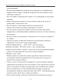
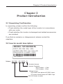
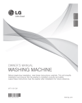
2-2 Inverter model description
MODEL: MV1002S0015G
INPUT: 1PH 2200 50Hz / 60Hz
OUTPUT: 3PH 220V 7.0A 150% 60S
FREQ RANGE: 0.1-400HZ 1.5KW
1201150001
Model: MV100 2S 0015 G
Constant torque
Inverter Capacity:
0015 means : 1.5kw
0150 means : 15kw
Voltage range:
2S means one-phase AC/220V input;
4T means three-phase AC/380V inpu
MV100 Series inverter
·7·
Operation Instruction of MV100 Series Inverter
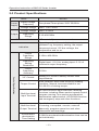
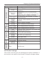
2-3 Product Specifications
Items
Power
Supply
Output
Rated voltage,
Frequency
MV100
One-phase/Three-phase 220V 50/60Hz
Voltage Range
220V: 170V~240V
Voltage Range
220V: 0~220V
Frequency
Range
0.10~400.00Hz
Control method
Indication
V/F control, Space vector control.
Operating status/Alarm definition/interactive
guidance: eg, frequency setting, the output
frequency/current, DC bus voltage, the
temperature and so on.
Control Specifications
Output
Frequency
Range
0.10Hz~400.00Hz
Frequency
Setting
Resolution
Digital input : 0.01 Hz, analog input: 0.1% of
maximum output frequency
Output
Frequency
Accuracy
0.01Hz
V/F Control
Setting V/F curve to satisfy various load
requirements.
Torque Control
Auto increase: auto raise torque by loading
condition; Manual increase:enable to set
0.0~20.0% of raising torque.
Multifunctional
Input Terminal
Six multi-function input terminals, realizing
functions including fifteen section speed control,
program running, four-section acceleration/
deceleration speed switch, UP/DOWN function
and emergency stop and other functions
Multifunctional
Output Terminal
Acceleration/
deceleration
Time Setting
2 multi-function output terminals for displaying
of running, zerospeed, counter, external
abnormity, program operat ion and other
information and warnings.
0~999.9s acceleration/deceleration time can be
set individually.
·8·
Chapter 2 Product Introduction
Items
PID Control
RS485
MV100
Built-in PID control
Standard RS485 communication function
(MODBUS)
Other Functions
Frequency
Setting
Analog input:0 to 10V, 0 to 20mA can be
selected;
Digital input: Input using the setting dial of the
operation panel or RS485or UP/DOWN.
Multi-speed
Six multifunction input terminals, 15 section
speed can be set
Automatic
voltage
regulation
Automatic voltage regulation function can be
selected
Protection/Warning
Function
Counter
Built-in 2 group of counters
Overload
150%, 60second (Constant torque)
Over Voltage
Over voltage protection can be set.
Under Voltage
Under voltage protection can be set.
Other
Protections
Overheat ,output shortcircuit, over current, and
parameter lock and so on.
Environment
Ambient
Temperature
-10℃ to 40℃ (non-freezing)
Ambient
Humidity
Max. 95% (non-condensing)
Altitude
Lower than 1000m
Vibration
Max. 0.5G
Structure
Cooling Mode
Protective
Structure
Installation
Mode
Forced air cooling
IP 20
Wall Mounted
2-4 Product storage
The inverter must be put in the packaging box before installation. If
the inverter is not used for the moment, during the storage, please
·9·
Operation Instruction of MV100 Series Inverter
pay attention those as below:
1. The products must be placed in the location with dry and without
dust and dirt.
2. The relative humidity of the environment is within 0~95%, and
without condensing.
3. The storage temperature of the environment must be within the
range of -26℃ to +65℃.
4. There are no corrosive gas and liquids in the storage
environment, and the product is away from direct sunlight.
It is better not to store the inverter for long time. Long time storage
of the inverter will lead to the deterioration of electrolytic capacity. If
it needs to be stored for a long time make sure to power it up one
time within a year and the power-up time should be at least above
five hours. When powered up the voltage must be increased slowly
with a voltage regulator to the rated voltage value.
·10·
Chapter 3 Installation of the Inverter
Chapter 3
Installation of the Inverter
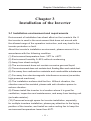
3-1 Installation environment and requirements
Environment of installation has direct effect on the inverter's life. If
the inverter is used in the environment that does not accord with
the allowed range of the operation instruction, and may lead to the
inverter protection or fault.
About the inverter's installation environment, please ensure it is in
accordance with the following condition:
(1) Environment temperature from -10℃ to +40℃
(2) Environment humidity 0~95% without condensing
(3) Away from direct sunlight
(4) The environment does not contain corrosive gas and liquid
(5) The environment does not contain dust, floating fiber and metal dust.
(6) Far away from radioactive materials and combustible substances
(7) Far away from electromagnetic interference sources (as welder,
high-powered machines)
(8) The installation surface shall be firm. Without vibration, the
vibration cannot be avoided, please add anti-vibration spacer to
reduce vibration.
(9) Please install the inverter to a location where it is good for
ventilation, inspection and maintenance, and away from heating unit
(as brake resistor).
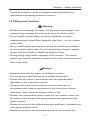
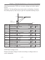
(10) Preserved enough space for inverter installation, especially
for multiple inverters installation, please pay attention to the laying
position of the inverter, and install an extra cooling fan to keep the
environment temperature lower than 45℃.
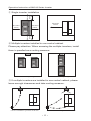
·11·
Operation Instruction of MV100 Series Inverter
Morethan
150mm
① Single inverter installation
Morethan
50mm
Morethan
50mm
Morethan
150mm
Morethan
50mm
② Multiple inverters installed in one control cabinet.
Please pay attention: When encasing the multiple inverters, install
them in paralled as a cooling measure.
Favorable placing
Unfavorable placing
③ If multiple inverters are installed in one control cabinet, please
leave enough clearances and take cooling measure.
Correct installation position of the fan
Incorrect installation position of the fan
·12·
Chapter 3 Installation of the Inverter
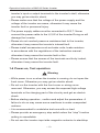
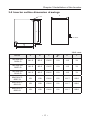
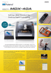
3-2 Inverter outline dimension drawings
E
C
A
D
10.5mm
B
F
Unit: mm
Model
A
B
C
MV100-2S0004-G
141.5
85.0
130.5
MV100-2S0007-G
141.5
85.0
MV100-2S0015-G
141.5
MV100-4T0007-G
E
F
5.0
113
74
130.5
5.0
113
74
85.0
130.5
5.0
113
74
151
100
139.6
5.2
111.7
88.6
MV100-4T0015-G
151
100
139.6
5.2
111.7
88.6
MV100-4T0022-G
151
100
139.6
5.2
111.7
88.6
·13·
D
Operation Instruction of MV100 Series Inverter
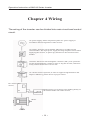
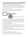
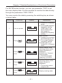
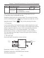
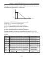
Chapter 4 Wiring
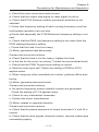
The wiring of the inverter can be divided into main circuit and control
circuit.
AC power supply. Please adopt three-phase AC power supply in
accordance allowed regulation of the inverter.
Air switch: Non-fuse circuit breaker (MCCB) or residual current
circuit breaker. The input power supply has large impulse current when
supplying the inverter, so please pay attention to the selection of the
breaker.
Contactor. Please use electromagnetic contactor (MC), note: please do
not use electromagnetic contator to start or stop the inverter, otherwise
it may reduce the inverter's service life.
AC current reactor. Optional, in order to suppress high harmonic and
improve efficiency, please choose a proper reactor.
DC current P/+
reactor
Brake resistor. It can improve the braking ability of
the internal brake unit of the inverter.
P1
Motor
Ground
·14·
Chapter 4 Wiring
4-1 Main Circuit Wiring
4-1-1 Peripheral Devices Description
(1) AC power supply
Use within the permissible power supply specifications of the
inverter.
(2) Moulded case circuit breaker: (MCCB)
When the power supply voltage is low or the input terminal short
circuit occurs, the breaker can provide protection, during inspection,
maintenance or the inverter is not running, you can cut off the
breaker to separate the inverter from the power supply.
(3)Magnetic contractor(MC)
The contractor can turn on and turn off the power of the inverter to
ensure safety.
(4) AC current reactor
a: Suppress high harmonic to protect the inverter.
b: Improve the power efficiency.
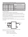
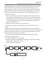
(5) Brake resistor
When the motor is braking, the resistor can avoid DC bus high
voltage of the inverter, and improve the braking ability of the internal
brake unit.
15KW or less the brake unit is built-in, please confirm it.
To select the brake resistor, please refer to section 4, chapter 9:
Appiled Braking resistor speeification.
U
V
W
B1
B2
Brake resistor
4-1-2 Main Circuit Wiring Notice
The MV100 series is a highly reliable product, but incorrect
peripheral circuit making or operation / handing method may shorten
the product life or damage the product.
·15·
Operation Instruction of MV100 Series Inverter
Before starting operation, always recheck the following items.
(1) Use crimping terminals with insulation sleeve to wire the power
supply and motor.
(2) Application of supply power to the output terminals (U,V,W) of
the inverter will damage the inverter. Never perform such wiring.
(3) After wiring, wire offcuts must not be left in the inverter.
Wire offcuts can cause an alarm ,failure or malfunction. Always keep
the inverter clean . When drilling mounting holes in an enclosure
etc., take are not to allow chips and other foreign matter to enter the
inverter.
(4) This inverter must be earthed. Earthing must conform to the
requirements of national and local safety regulations and electrical
codes.
(5) Use the thickest possible earth cable.
(6) The grounding point should be as near as possible to the
inverter, and the ground wire length should be as short as possible.
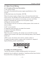
(7) Where possible, use independent earthing for the inverter. If
independent earthing is impossible, use joint earthing (Ⅰ, Ⅱ) where
the inverter is connected with the other equipment at an earthing
point. Joint earthing as in (Ⅲ) must be avoided as inverter is
connected with the other equipment by a common earth cable.
Correct
Correct
Incorrect
Ⅰ
Ⅱ
Ⅲ
(8) To prevent a malfunction due to noise, keep the signal cables
more than 10 cm away from the power cables.
·16·
Chapter 4 Wiring
(9)The overall wiring length should be 100 m maximum.
Especially for long distance wiring, the fast-response current limit
function may be reduced or the equipment connected to the inverter
output side may malfunction or become faulty under the influence of
a charging current due to the stray capacity of the wiring. therefore,
note the overall wiring length.
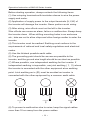
(10) Do not install a power factor correction capacitor, surge
suppressor or radio noise filter on the inverter output side.
U
inverter
M
V
Motor
W
It is strictly prohibited to connect capacitanceresistance ab sorbing devices to the output side.
(11) Before starting wiring or other work after the inverter is operated,
wait for at least 10 minutes after the power supply has been switched
off, and check that there are no residual voltage using a tester or the
like. The capacitor is charged with high voltage for some time after
power off and it is dangerous.
(12) Electromagnetic wave interference
The input/output (main circuit) of inverter includes high frequency
components, which may interfere with the communication devices
(such as AM radios) used near the inverter. In this case,set the EMC
filter valid to minimize interference.
(13) Across P/+ and PR terminals, connect only an external
regenerative brake discharge resistor. Do not connect a mechanical
brake.
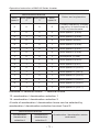
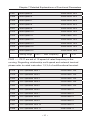
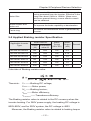
4-1-3 Peripheral Devices Specifications
Check the motor capacity of the inverter you purchased .
Appropriate peripheral devices must be selected according to
·17·
Operation Instruction of MV100 Series Inverter
the capacity. Refer to the following list and prepare appropriate
peripheral devices:
Applicable Inverter
Type
Input Side
Motor Main Circuit Breaker
Magnetic
Input
Output Cable Type Selection
contractor
voltage
(A)
(kW)
(mm2)
(A)
MV100-2S-0004-G
220V
0.4
2.5
16
12
MV100-2S-0007-G
220V
0.75
2.5
16
12
MV100-2S-0015-G
220V
1.5
2.5
32
18
MV100-4T-0007-G
380V
0.75
2.5
16
12
MV100-4T-0015-G
380V
1.5
2.5
16
12
MV100-4T-0022-G
380V
2.2
2.5
16
12
*The above data are for reference only.
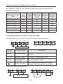
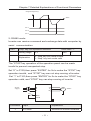
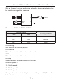
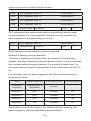
4-1-4 Specification of main circuit terminal
The arrangement of main circuit terminals is shown below:
E
T/L3
S/L2
R/L1
U
V
W
B1
B2
POWER SUPPLY
Terminal
Symbol
Terminal Name
Description
R,S,T
AC power input
Connect to the commercial power
supply.
U,V,W
Inverter output
Connect a three-phase motor.
B1, B2
Brake resistor
connection
Connect brake resistor.
Earth (ground)
For earthing (grounding) the inverter
chassis. Must be earthed (grounded).
E
Cable connection examples
E
R/L1
S/L2
U
1PH AC 220V
V
Motor
·18·
W
B1
B2
Braking Resistor
Chapter 4 Wiring
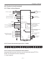
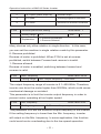
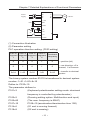
4-2 Control circuit terminal
4-2-1 Basic wiring diagram
Power supply
Grounding
Forward rotation
Reverse rotation
R
S
T
E
U
V
W
FWD
B1
REV
B2
GND
M
Motor
To connect
brake resistor
+10V (fequency
10KΩ
setup power supply)
0-10V
frequency setup
0-20mA
frequency setup
FIV
RC Multifunctional
output termina
FIC
RA (3A/250VAC.
3A/30VDC)
GND
RB
M01 Multifunctional
output terminal
S1
MCM
S2
Multifunctional
input terminal
+24V Assistant DC
power supply
S3
S4
FOV
GND
GND
RS+
Voltmeter
(0-10V)
RS-
RS485
4-2-2 Control terminals layout (0.4~1.5kW)
RA
RB RC
FWD REV S1
S2
S3
S4 GND FOV FIC 10V FIV GND MCM M01
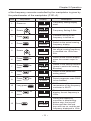
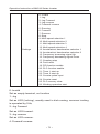
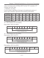
4-2-3 Control circuit terminals description
Indicates that terminal functions can be selected using P315 to
P329. (I/O terminal function selection)
(1) Input signals
·19·
Operation Instruction of MV100 Series Inverter
Type
Terminal
Terminal Name
Symbol
Description
Refer
to page
Contact input
FWD
Forward
rotation start
Turn on the FWD signal to start
forward rotation and turn it off
to stop. (multifunctional input
terminal)
35
REV
Reverse
rotation start
Turn on the REV signal to start
reverse rotation and turn it off
to stop. (multifunctional input
terminal)
35
S1
multifunctional input terminal 1
35
S2
multifunctional input terminal 2
35
S3
multifunctional input terminal 3
35
S4
multifunctional input terminal 4
35
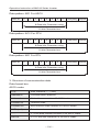
Frequency setting power supply.
(FIV, FIC)
36
FIV
Inputting 0 to 10VDC provides
Frequency
the maximun output frequency at
setting(voltage) 10V and makes input and output
proportional.
36
FIC
Inputting 0 to 20mADC provides
Frequency
the maximun output frequency
setting(current) at 20mA and makes input and
output proportional.
36
+10V
Frequency setting
GND
Frequency
setting power
supply
Frequency
setting
common
Common terminal for terminals
FIV, FIC, +10V, and analog
output terminal FOV, FOC
36
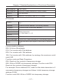
(2) Output signals
Type
Terminal
Terminal Name
Symbol
Contact
output
MO1
Multifunction
output terminal Permissible load 24VDC 0.1A
(optical coupling)
Contact output
RA
RB
RC
Description
Relay out 1
Abnormal: No conduction across
YA-YB (AcrossYB -YCcontinuity),
Nor-mal: No conduction across
YC-YB (Across YB-YA continuity).
Contact capacity: 250VAC / 3A,
30VDC / 3A
·20·
Refer to
page
36
36
Chapter 4 Wiring
Type
Terminal
Terminal Name
Symbol
Analog
output
FOV
Analog voltage
output
Description
Refer to
page
Output signal 0 to 10VDC,
permissible load current 1mA.
The output signal is proportional
to the output frequency.
36
(3)Communication
RS485
RS+
Frequency
setting (current)
RS_
Frequency
setting
common
With the RS+, RS, connector,
communication can be made
through RS486.
36
36
4-2-4 Wiring instructions
(1) Use shielded or twisted cables for connection to the control
circuit terminals and run them away from the main and power
circuits ( including the 200V relay sequence circuit ).
(2) Use two or more parallel micro-signal contacts or twin contacts
to prevent a contact faults when using contact inputs since the
control circuit input signals are micro-currents.
(3) Do not apply a voltage to the contact input terminals of the
control circuit.
(4) Always apply a voltage to the alarm output terminals (RA, RB,
RC, MO1) via a relay coil, lamp, etc.
(5) It is recommended to use the cables of 0.75mm2 gauge for
connection to the control circuit terminals.
(6) The wiring length should be 30m maximum.
·21·
Operation Instruction of MV100 Series Inverter
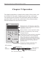
Chapter 5 Operation
The digital manipulator is located at the center of the inverter, and
it is divided into two parts: displaying part and key control part.
The displaying part indicates the parameter setting and different
operation status, and the key control part is the communication
channel between the user and the inverter.
Displaying part: set frequency, operation
frequency, current, parameter setting and
irregularity content, etc.
Status indicator: various operation status
Operation command key: start running
Programming key
Stop/ Reset key: stop running or reset after
an interrupt because of any irregularity
Shift / data enter key: enter the data to
modify a parameter and display the status,
parameters, set frequency, output current,
forward / backward rotating, physical
quantities, etc.
Frequency set knob: enter the main
frequency by rotating this knob
LED indicators:
LED
Indicators:
Red:Running
RUN
S TO P
F WD
Red: Running stopped
·22·
REV
Red: Reverse
Running
Red: Forward Running
Chapter 5 Operation
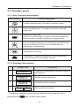
5-1 Opeation panel
5-1-1 Key Function description
Key Symbol
Function description
Function selecting key, for select a function menu
Figure modifying key, for modify a function code and
parameter
Shift key or enter key
Shift to an another digit or switch to another display by
short-pressing, confirm a setting by long-pressing
Turn to another frequency by rotating the potentiometer
when the frequency is set to be controlled by the
manipulator potentiometer
Command for running
Command for stopping (applicable in the manipulator
controlled status) or reset after an fault
5-1-2 Displays description
Display item
Description
1
F00.0
Frequency setting after the power supply is
switched on
2
H00.0
Actual running frequency
3
A00.0
Current for motor running
4
Frd rEu
Motor rotating direction
* The above display items can be switched and read by short
pressing the key on the main menu.
·23·
Operation Instruction of MV100 Series Inverter
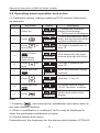
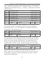
5-2 Operating panel operation instruction
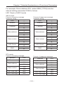
(1) Parameter setting <taking modifying P104 reverse Valid setup
as example>
Program
Key name
1
Power on
2
Press
3
4
5
6
7
8
9
Press
Display
STOP
F00.0
STOP
FWD
P000
for
four times
Quickly press
2 times
(quick press
means shift)
Press
FWD
for
once
Press and hold
Press
Press and hold
Press
STOP
FWD
P004
STOP
FWD
P004
STOP
FWD
P104
STOP
FWD
0001
STOP
FWD
0000
STOP
FWD
P105
STOP
FWD
F00.0
Description
① Display the frequency
setting (initial display).
② The inverter is standing by.
To enter the parameter setup
state, and the first letter blinks
(means modifiable item)
The digit is modified into "4"
from "0".
Shift leftward for two digits
and the third digit will clicker.
The digit is modified into "1"
from "0".
Enter the parameter setting
interface.
Modified "1" into "0".
To confirm that the value
"P104" has been modified.
Return back to the initial
display.
Note:
can interrupt the modification and return back to
1. Pressing the main display interface.
2. When a modification is confirmed, An Err may be displayed to
show the parameter modification is failed.
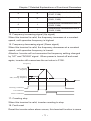
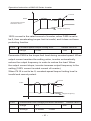
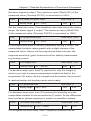
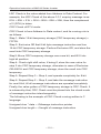
(2) Status display and inquiry
Parameter set: the frequency for the startup and shutdown (P102=0)
·24·
Chapter 5 Operation
of the frequency converter controlled by the manipulator is given by
the potentiometer of the manipulator (P101=3).
Step
Key name
Display
STOP
1
Power on
2
Rotate
3
Press
4
Press
5
Rotate
6
Press
once
for
RUN
7
Press
once
for
RUN
8
Press
once
for
RUN
9
Press
once
for
RUN
10
Long press
11
Press
twice
12
Press
FWD
F00.0
STOP
FWD
F05.0
RUN
FWD
F05.0
RUN
FWD
F05.0
RUN
FWD
H15.0
FWD
A00.0
FWD
Frd
FWD
P000
FWD
P006
RUN
FWD
022.8
for
RUN
FWD
F15.0
STOP
FWD
F15.0
·25·
Description
Frequency setting display
state.
Frequency Setting 5.0Hz.
Forward running of the
frequency is turned on.
Switch to the actual running
frequency display.
Modify the set frequency, and
the actual running frequency
is modified into 15Hz from
5Hz.
Switch to the current display
when the current output is
0A.
Switch to the setting interface
(press to switch the rotating
direction)
Switch to the parameter
setting status.
Select parameter code P006
to be modified.
P006 content: the current
temperature of the frequency
converter is 22.8℃.
Return back to the main
display, the set frequency is
15Hz.
During the frequency
converter is decelerating
before stop, the key will
flicker and then the and
keys will turn on, and the set
frequency displayed is 15Hz
Operation Instruction of MV100 Series Inverter
Note: The set frequency, running frequency, output current and
running speed of the frequency converter can be monitored by
switching keys during operation, and the main display can be
modified by P000 setting as per the practical requirement, and
meanwhile the related content can be monitored by the user through
P001-P018.
·26·
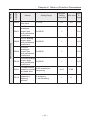
Chapter 6 Table of Function Parameters
Chapter 6
Table of Function Parameters
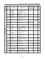
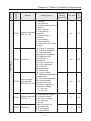
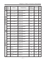
This chapter explains the “PARAMETERS” for use of this product.
Aways read this instructions before use.
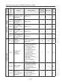
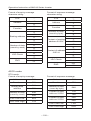
Parameter list
Parameters
Function
Name
Setting Range
P000
Main display
data selection
P001
Display the set
Read only
frequecy.
Display
P002 the output
frequency
0-32
Minimum
Refer
Setting Initial value To
increments
Page
1
1
42
-----
-----
43
Read only
-----
-----
43
Monitor
functions
P003
Display the
output current
Read only
-----
-----
43
P004
Display the
motor speed.
Read only
-----
-----
43
Display the DC
P005 bus voltage
Read only
value.
-----
-----
43
Display the
P006 temperature of Read only
inverter.
-----
-----
43
P007 Display PID
Read only
-----
-----
44
P010 Alarm record 1 Read only
-----
-----
44
P011 Alarm record 2 Read only
-----
-----
44
P012 Alarm record 3 Read only
-----
-----
44
P013 Alarm record 4 Read only
-----
-----
44
·27·
Operation Instruction of MV100 Series Inverter
Parameters
Function
Name
Setting Range
Minimum
Refer
Setting Initial value To
increments
Page
Monitor
functions
Basic functions
The frequency
P014 setting in the
Read only
last alarm.
-----
-----
44
The output
P015 frequency in
last alarm.
Read only
-----
-----
44
The output
P016 current in last
alarm.
Read only
-----
-----
44
The output
P017 voltage in last
alarm.
Read only
-----
-----
44
The output DC
P018 bus voltage in Read only
last alarm.
-----
-----
44
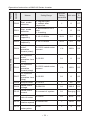
Digital
P100 frequency
setting
0.00—Maximum
frequency
0.01
0.00
46
Frequency
P101 setting
selection
0: Digital frequency
setting (P100)
1: Analog voltage
(0—10VDC)
2: Analog current
(0—20mADC )
3. Setting dial
(Operation panel)
4 UP/DOWN
frequency setting
5: RS485
communication
frequency setting
1
0
46
Start signal
P102
selection
0: Operation panel
(FWD/REV/STOP)
1: I/O terminal
2: Communication
(RS485)
1
0
49
“stop” key
P103 lock operation
selection
0: “Stop”key lock
mode invalid
1: “Stop” key lock
mode valid
1
1
51
·28·
Chapter 6 Table of Function Parameters
Parameters
Function
Name
Setting Range
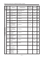
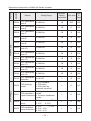
P104
Reverse
rotation
prevention
selection
0: Reverse rotation
disallowed
1: Reverse rotation
allowed
P105
Maximum
frequency
P106
Minimum
Refer
Setting Initial value To
increments
Page
Basic functions
1
1
52
Minimum
frequency~400.00Hz
0.01
0.00
52
Minimum
frequency
0.00~maximum
frequency
0.01
0.00
52
P107
Acceleration
time 1
0~999.9s
0.1
53
P108
Deceleration
time 1
0~999.9s
0.1
Depends
on
models
P109
V/F maximum
voltage
V/F intermediate
voltage ~ 500.0V
0.1
400.0
53
P110
V/F base
frequency
V/F intermediate
frequency ~ max.
frequency
0.01
50.00
53
V/F
P111 intermediate
voltage
V/F minimum voltage
~ V/F maximum
voltage
0.1
Changing
53
V/F
P112 intermediate
frequency
V/F minimum
frequency ~ V/F base
frequency
0.01
2.50
53
53
P113
V/F minimum
voltage
0~V/F intermediate
voltage
0.1
15.0
54
P114
V/F minimum
frequency
0~V/F intermediate
frequency
0.01
1.25
54
P115
Carrier
frequency
1.0K-15.0K
0.1
Changing
56
P116
Automatic
carrier line up
Reserved
1
0
*
P117
Initialization of 8: Initialization of
parameters
Factory Setting
1
0
56
1
0
56
P118 Parameter lock
0: Unlock parameters
1: Lock up parameters
·29·
Operation Instruction of MV100 Series Inverter
Parameters
Function
Name
Setting Range
Minimum
Refer
Setting Initial value To
increments
Page
Basic functions
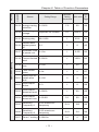
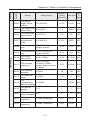
P200
Start mode
selection
0: regular start
1: restart after
inspection
1
0
57
P201
Stop mode
selection
0: deceleration to a
stop
1: coasting
1
0
58
P202
Starting
frequency
0.10~10.00Hz
0.01
0.5
58
P203
Stopping
frequency
0.10~10.00Hz
0.01
0.5
59
P204
DC injection
brake
operation
current (start)
0~150% rated motor
current
1%
100%
59
0.1
0
59
1%
100%
60
0.1
0
60
DC injection
brake
0~25.0S
P205
operation time
(start)
P206
DC injection
brake
operation
current (stop)
0~150% rated motor
current
DC injection
brake
P207
0~25.0S
operation time
(stop)
P208 Torque boost
0~20.0%
1
5%
60
Rated motor
P209
voltage
0~500.0V
0.1
380.0
61
0~current of system
0.1
Changing
61
0.1
40%
61
P210
Rated motor
current
P211
No load current
0~100%
ratio of motor
P212
Rated motor
0~6000r/min
rotation speed
1
1420
61
P213
Number of
motor poles
1
4
61
0~20
·30·
Chapter 6 Table of Function Parameters
Parameters
Function
Name
Setting Range
Minimum
Refer
Setting Initial value To
increments
Page
Basic functions
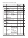
P214
Rated motor
slip
0~10.00Hz
0.01
2.50
61
P215
Rated motor
frequency
0-400.00Hz
0.01
50.00
62
P216
Resistance of
stator
0-100Ω
0.01
0
62
P217
Resistance of
rotor
0-100Ω
0.01
0
62
P218
Self inductance
0-1.000H
of rotor
0.01
0
62
0601
0
63
Mutual
P219 inductance of
rotor
0-1.000H
I/O functions
P300
FIV minimum
voltage input
0~FIV maximum
voltage
0.1
0
63
P301
FIV maximum
voltage input
FIV minimum
voltage~10V
0.1
10.0
63
P30 2
FIV input filter
time
0~25.0S
0.1
1.0
63
P303
FIC minimum
current input
0~FIC maximum
current
0.1
0
64
P304
FIC maximum
current input
FIC minimum current
input~20mA
0.1
20.0
64
P305
FIC input filter
time
0~25.0S
0.1
1.0
64
P306
FOV minimum 0~FOV maximum
voltage output voltage
0.1
0
65
P307
FOV maximum FOV maximum
voltage output voltage output~10V
0.1
10.0
65
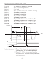
P310
Frequency of
low analog
0.00
66
P311
Direction of low
0/1
analog
1
0
66
P312
Frequency of
high analog
0.01HZ
50.00
66
0~600.00
0~600.00
·31·
Operation Instruction of MV100 Series Inverter
Parameters
Function
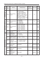
P313
Name
Direction of
high analog
Analog input
P314 reverse
selection
P315
Input terminal
FWD (0~32)
Input terminal
P316
REV (0~32)
I/O functions
P317
Input terminal
S1 (0~32)
P318
Input terminal
S2 (0~32)
Input terminal
P319 S3
(0~32)
Input terminal
P320 S4
(0~32)
P321
Reserved
(0~32)
P322
Reserved
(0~32)
Setting Range
Minimum
Refer
Setting Initial value To
increments
Page
0/1
1
0
66
0/1
1
0
67
0: Invalid
1: Jog
2: Jog Forward
3: Jog reverse
4: Forward/ reverse
5: Run
6: Forward
7: Reverse
1
6
69
1
7
69
1
1
69
1
18
69
1
15
69
1
16
69
1
8
69
1
9
69
8: Stop
9: Multi-speed 1
10: Multi-speed 2
11: Multi-speed 3
12: Multi-speed 4
13: Accleration/
Deceleration terminal 1
14: Accleration/
Deceleration terminal 2
15: Frequency
increase signal (UP)
16: Frequency
decrease signal
(DOWN)
17: Emergency stop
signal
18:Inverter reset
signal
19: PID in running
20: PLC in running
21: Start signal for
timer 1
22: Start signal for
timer 2
23: Counter pulse
signal
24: Counter reset
signal
25: Memory clear
26: Start winding
operation
·32·
Chapter 6 Table of Function Parameters
Parameters
Function
Name
Setting Range
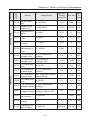
I/O functions
0: Invalid
1: In running
2: Frequency reached
3: Alarm
4: Zero speed
5: Frequency 1
Output terminal
P323
reached
M01 (0~32)
6: Frequency 2
reached
7: Accleration
8: Deceleration
9: Indication for under
voltage
10: Timer 1 reached
11: Timer 2 reached
12: Indication for
completion of phase
13:Indication for
completion of
P324 Reserved
procedure
14: PID maximum
15: PID minimum
16: 4-20mA
disconnection
17: Overload
18: Over torque
26: Winding operation
completed
27: Counter reached
Alarm output
28: Intermediate
P325 terminal RA,
counter reached
RB, RC (0~32) 29:Water supply by
constant voltage
“1” turn on
“0” turn off
0: Frequency output
Output terminal 1: current output
P326
2: Dc bus voltage
FOV (0~7)
3: Ac voltage
4: Pulse
output,1pulse/ Hz
5: 2pulses/Hz
P327 Reserved
6: 3 pulses/Hz
7: 6 pulses/Hz
·33·
Minimum
Refer
Setting Initial value To
increments
Page
1
01
75
1
02
75
1
03
75
1
0
79
1
1
79
Operation Instruction of MV100 Series Inverter
Parameters
Function
Name
Setting Range
Minimum
Refer
Setting Initial value To
increments
Page
Secondary application
P400
Jog frequency 0.00~maximum
setting
frequency
0.01
5.00
80
P401
Acceleration
time 2
0~999.9s
0.1S
10.0
81
P402
Deceleration
time 2
0~999.9s
0.1S
10.0
81
P403
Acceleration
time 3
0~999.9s
0.1S
20.0
81
P404
Deceleration
time 3
0~999.9s
0.1S
20.0
81
P40 5
Acceleration
time 4/Jog
acceleration
time
0~999.9s
0.1S
2.0
81
P406
Deceleration
time 4/Jog
deceleration
time
0~999.9s
0.1S
2.0
81
Designated
P407 value of
counter
0~999.9s
1
100
81
Intermediate
P408 value of
counter
0~999.9s
1
50
81
Limitation of
P409 acceleration
torque
0~200%
1%
150%
81
Limitation of
P410 constant speed 0~200%
torque
1%
00
82
P411
Over voltage
prevention
selection in
deceleration
0/1
1
1
82
P412
Automatic
Voltage
regulation
selection
0~2
1
1
83
·34·
Chapter 6 Table of Function Parameters
Parameters
Function
Name
Setting Range
AutomaticP413 energy-saving 0~100%
selection
P414
DC Braking
voltage
Depends on models
Minimum
Refer
Setting Initial value To
increments
Page
1%
00
84
0.1
800.0
84
P415 Braking duty
40~100%
1
50%
84
Restart after
P416 instant power
off
0~1
1
0
85
1
5.0S
86
1
150%
86
P417
Allowable time
0~10s
of power cut
Secondary application
Flank restart
P418 Current limited 0~200%
level
P419
Flank restart
time
0~10s
1
50
87
P420
Fault restart
times
0~5s
1
0
87
0~100
2
2
87
0~3
1
0
88
1
00
88
Delay time for
P421 restart after
fault
P422
Over torque
action
P423
Over torque
0~200%
detection level
P424
Over torque
detection time
0~20.0S
0.1
00
88
P425
Reaching
Frequency 1
0.00~maximum
frequency
0.01
100
89
P426
Reaching
Frequency 2
0.00~maximum
frequency
0.01
5.0
89
0.1
0
89
P427 Timer 1 setting 0~999.9s
·35·
Operation Instruction of MV100 Series Inverter
Parameters
Function
Name
Setting Range
P428 Timer 2 setting 0~999.9s
ConstantP429 speed torque
limiting time
0~999.9s
Width of arrival
P430 of frequency in 0.00~2.00
hysteretic loop
Minimum
Refer
Setting Initial value To
increments
Page
1
0
89
0.1
Changing
89
0.01
0.50
90
Secondary application
P431
Jump
frequency 1
0.00~maximum
frequency
0.01
0
90
P432
Jump
frequency 2
0.00~maximum
frequency
0.01
0
90
P433
Jump
frequency
0.00~2.00
hysteresis loop
width
0.01
0.50
90
P434
UP/DOWN
0~10.00Hz
frequency step
0.01
0.1
0: memory
1: No Memory
1
0
UP/DOWN
frequency
P435
Memory
options
P500
PLC memory
mode
0~1
1
0
90
P501
PLC starting
mode
0~1
1
0
91
PLC running
mode
0: PLC stops after
running for one cycle
1: PLC stop mode, it
stops after running for
one cycle
2: PLC cycle running
3: PLC stop mode,
cycle running mode
4: PLC operates at the
last frequency after
running for one cycle.
1
0
92
0.01
10.0
92
P502
P503 Multi-speed 1
0.00~maximum
frequency
·36·
Chapter 6 Table of Function Parameters
Parameters
Function
Name
Setting Range
Minimum
Refer
Setting Initial value To
increments
Page
Secondary application
PLC operation
P504 Multi-speed 2
0.00~maximum
frequency
0.01
15.00
92
P505 Multi-speed 3
0.00~maximum
frequency
0.01
20.00
92
P506 Multi-speed 4
0.00~maximum
frequency
0.01
25.00
92
P507 Multi-speed 5
0.00~maximum
frequency
0.01
30.00
93
P508 Multi-speed 6
0.00~maximum
frequency
0.01
35.00
93
P509 Multi-speed 7
0.00~maximum
frequency
0.01
40.00
93
P510 Multi-speed 8
0.00~maximum
frequency
0.01
45.00
93
P511 Multi-speed 9
0.00~maximum
frequency
0.01
50.00
93
P512 Multi-speed 10
0.00~maximum
frequency
0.01
10.00
93
P513 Multi-speed 11
0.00~maximum
frequency
0.01
10.00
93
P514 Multi-speed 12
0.00~maximum
frequency
0.01
10.00
93
P515 Multi-speed 13
0.00~maximum
frequency
0.01
10.00
93
P516 Multi-speed 14
0.00~maximum
frequency
0.01
10.00
93
P517 Multi-speed 15
0.00~maximum
frequency
0.01
10.00
93
P518
PLC operation
0~999.9s
time 1
1S
100
93
P519
PLC operation
0~999.9s
time 2
1S
100
93
P520
PLC operation
0~999.9s
time 3
1S
100
93
P521
PLC operation
0~999.9s
time 4
1S
100
93
·37·
Operation Instruction of MV100 Series Inverter
Parameters
Function
Name
Setting Range
Minimum
Refer
Setting Initial value To
increments
Page
PLC operation
PID operation
P522
PLC operation
0~999.9s
time 5
1S
100
93
P523
PLC operation
0~999.9s
time 6
1S
0
93
P524
PLC operation
0~999.9s
time 7
1S
0
93
P525
PLC operation
0~999.9s
time 8
1S
0
93
P526
PLC operation
0~999.9s
time 9
1S
0
93
P527
PLC operation
0~999.9s
time 10
1S
0
93
P528
PLC operation
0~999.9s
time 11
1S
0
93
P529
PLC operation
0~999.9s
time 12
1S
0
94
P530
PLC operation
0~999.9s
time 13
1S
0
94
P531
PLC operation
0~999.9s
time 14
1S
0
94
P532
PLC operation
0~999.9s
time 15
1S
0
94
P533
PLC operation
0~32767
direction
1
0
94
P600
PID starting
mode
1
0
97
1
0
98
1
0
98
1
0
98
0: PID disable
1: PID start
2: PID start by
external terminal
0: Negative feedback
PID operation mode
P601
mode selection 1: Positive feedback
mode
P602
PID action set
point
0: figure mode (P604)
1: FIV
2: FIC
P603
0: FIV
1: FIC
PID feedback
2: FIV - FIC
value selection
3: FIC - FIV
·38·
Chapter 6 Table of Function Parameters
Parameters
Function
Name
PID figure
P604 target value
setting
Setting Range
0.0~100.0%
Minimum
Refer
Setting Initial value To
increments
Page
0.1%
0.0%
99
P605
PID upper limit
0~100.0%
alarm value
1%
100%
100
P606
PID lower limit
0~100.0%
alarm value
1%
0%
101
0.0~200.0%
0.1%
100%
101
0.0~200.0 S.0
means closed
0.1s
0.1s
101
PID
P607 proportional
band
PID operation
P608
PID integral
time
P609
PID differential 0.00.0~20.00 S.0
time
means closed
0.1s
0.0
101
P610
PID action
step-lergth
0.00~1.00Hz
0.01
0.10Hz
101
P611
PID standby
frequency
0.00~120.0Hz
(0.00Hz) 0.00Hz
means sleep function
is closed
0.01
0.00Hz
102
P612
PID standby
duration
0~200s
1S
10s
102
P613
PID wake-up
value
0~100%
1%
0
102
1
1000
103
PID
0~10000
P614 corresponding
value of display
P615
PID diqit of
display
1~5
1
1
103
P616
PID decimal
0~4
digits of display
1
1
103
P617
PID upper limit
0~max. frequency
frequency
0.01
48.00
P618
PID lower limit
0~max. frequency
frequency
0.01
20.00
·39·
Operation Instruction of MV100 Series Inverter
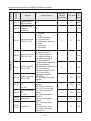
Parameters
Function
Name
Setting Range
PID operation
0: Always work (PID
function open)
1: When feedback
reaches upper limit
(P605), it will work at
Min-frequency. When
feedback reaches
lower limit (P606), PID
will begin to work.
RS-485 Communication
P619
PID working
mode
P700
0: 4800bps
Communication 1: 9600 bps
speed
2: 19200 bps
3: 38400 bps
Minimum
Refer
Setting Initial value To
increments
Page
1
0
0
0: 8N1 FOR ASC
1: 8E1 FPR ASC
Communication 2: 8O1 FOR ASC
P701
mode
3: 8N1 FOR RTU
4: 8E1 FOR RTU
5: 8O1 FOR RTU
P702
Communication
0~240
address
Advanced
0: Locked
P800 application
1: Unlocked
parameter lock
Advanced application
P801
System 50Hz/
60Hz setting
P802
Constant
torque or
0: Constant torque
variable torque 1: Variable torque
selction
Over-voltage
P803 protection
setting
0~50Hz 1~60Hz
104
104
1
0
104
1
111
111
1
0
111
1
0/1
111
changing
1
changing 112
Under-voltage
P804 protection
changing
setting
1
changing 112
1
85/95℃ 112
P805
Overtemperature
protection
setting
40~120℃
·40·
Chapter 6 Table of Function Parameters
Parameters
Function
P806
Name
Setting Range
Current display
0~10.0
filter time
Minimum
Refer
Setting Initial value To
increments
Page
0.1
2.0
112
0-10V
analogue
P807 output low
0-65535
end calibration
coefficient
1
-
112
0-10V analog
output high
0-65535
end calibration
coefficient
1
-
113
0-20mA
analogue
P809 output low
0-65535
end calibration
coefficient
1
-
113
0-20mA analog
output high
0-65535
end calibration
coefficient
1
-
113
Compensation
0.00~maximum
P811 frequency point
frequency
for dead time
0.01
0.00
1
0
P808
Advanced application
P810
P812
UP/DOWN
frequency
Memory
options
0: memory
1: No Memory
·41·
Operation Instruction of MV100 Series Inverter
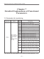
Chapter 7
Detailed Explanations of Functional
Parameters
7-1 Parameters for monitoring
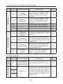
Parameters
P000
Name
Main display
data selection
(Initial value:
00)
Setting range
(00-32)
Setting
Range
Descrption
00
Displays the set frequency
01
Displays the inverter output frequency
02
Displays the inverter output current
03
Displays the motor speed
04
Displays the DC bus voltage
05
Displays the inverter temperature
09
Displays record of last faults (1)
10
Displays record of last faults (2)
11
Displays record of last faults (3)
12
Displays record of last faults (4)
13
Displays the recently set frequency of
the inverter when the fault occured
14
Displays the recently output frequency
of the inverter when the fault occured
15
Displays the recently output current of
the inverter when the fault occured
16
Displays the recently output voltage of
the inverter when the fault occured
17
Displays the recently DC bus voltage
of the inverter when the fault occured
18
Displays the recently temperature of
the inverter when the fault occured
User can set the initial display of the inverter through parameter P000.
·42·
Chapter 7 Detailed Explanations of Functional Parameters
For example, in order to monitor rotation speed through the
operation panel , user can set parameter P000 to “03”.
Initial value of P000 is “00”, therefore , if not been changed,
inverter will display the set frequency .
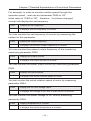
P001
Display the set frequency
It displays the set frequency of inverter.
You can monitor the set frequency of inverter by examining the
content of this parameter.
P002
Display the output frequency
It displays the present output frequency of inverter.
You can monitor the present output frequency of the inverter by
examining parameter P002.
P003
Display the output current
It displays the output current of inverter.
You can monitor the actual output current by examining parameter
P003.
P004
Display the motor speed
It displays the actual rotation speed of motor.
You can monitor the actual rotation speed of motor by examining
parameter P004.
P005
Display the DC bus voltage value
It displays the voltage of DC bus in main circuit of inverter.
You can monitor the actual voltage of DC bus by examining
parameter P005.
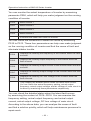
P006
Display temperature of inverter
It displays the actual temperature of inverter.
·43·
Operation Instruction of MV100 Series Inverter
You can monitor the actual temperature of inverter by examining
parameter P006, which will help you make judgment on the running
condition of inverter.
P010
Alarm record 1
P011
Alarm record 2
P012
Alarm record 3
P013
Alarm record 4
It records the latest four faults of inverter.
You can check the conditions of latest four faults by examining
P010 to P013. These four parameters can help user make judgment
on the running condition of inverter and find the cause of fault and
eliminate hidden trouble.
P014
Displays the recently set frequency of the inverter when the fault
occured
P015
Displays the recently output frequency of the inverter when the
fault occured
P016
Displays the recently output current of the inverter when the fault
occured
P017
Displays the recently output voltage of the inverter when the fault
occured
P018
Displays the recently DC bus voltage of the inverter when the
fault occured
They display the detailed status when the latest fault occurs.
You can check the actual frequency setting, actual output
frequency, actual output voltage, and dc voltage of main circuit in
inverter by examining these parameters respectively.
You can check the detailed status when the latest fault occurs
by examining the content of P014--P018. You can examine the
frequency setting, actual output frequency, and actual output
current, actual output voltage, DC bus voltage of main circuit.
According to the above data, you can analyze the cause of fault
and find a solution quickly, which will help maintenance personnel in
repair work.
·44·
Chapter 7 Detailed Explanations of Functional Parameters
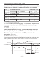
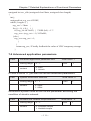
For MV100 series inverter, you can use parameter “F.00” to set
the main display data. It’s also possible to monitor the data directly
through the parameters “P001~P018”.
You may monitor the data by pressing the switching key as shown
in below table:
Procedure
1
2
3
4
5
Press key
Turn on power
for
once
FWD
F50.0
FWD
RUN
FWD
H50.0
for
STOP
for
RUN
once
Press
Explanation
F50.0
once
Press
STOP
RUN
Press
Press
Display
FWD
A00.0
FWD
Frd
·45·
① Inverter is in standby
mode.
② The keypad displays
frequency setting.
FREE light is on,
which means that
the keypad is
displaying frequency
setting
Start inverter
① Inverter is in running
and RUN light is on.
② The image displays
frequency setting.
Forward light is on;
inverter is in Forward
state.
Switch display; stop
switching when actual
output frequency is
displayed.
Inverter is in Forward
running state.
① The actual output
frequency is 50.0Hz.
Switch display; stop
switching when actual
output current is
displayed.
① The actual current
output is 0A
Display running state.
Operation Instruction of MV100 Series Inverter
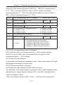
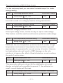
7-2 Basic parameters
P100
Digital frequency setting
Setting range
(Initial value: 0.00Hz)
0.00-Maximum frequency
Unit
0.01
When P101 is set to 0, inverter works in Digital frequency setting
mode. The frequency value is set by P100.
During running, you can change frequency by modifying the content
of parameter P100 or by pressing “ ” key or “ ” key to
change frequency. If you change frequency by modifying P100,
when the inverter stops running or when power is off, the modified
content can be remembered.
If you change frequency by pressing “ ” key or “ ”
key, when the inverter stops running or power is off, the modified
content will not be remembered; instead the original P100 will be
remembered. When the inverter is started next time, it will operate
at the original value of P100.
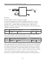
P101
Frequency setting selection
Initial value : 0
Setting range
0-5
Unit
1
Explanation
0: Digital frequency setting (P100)
1: Analog voltage (0—10VDC)
2: Analog current (0—20mADC )
3. Setting dial (Operation panel)
4. UP/DOWN frequency setting
5: RS485 communication frequency setting
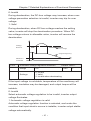
Frequency setting selection can be used to decide the output
frequency of inverter.
0: Digital frequency setting
The output frequency of inverter is decided by P100. Generally
speaking, you can change output frequency by pressing the “ or “ ” key on Keypad. Refer to P100 for details.
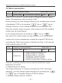
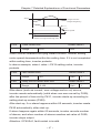
1: Analog voltage mode (0~10VDC)
·46·
”
Chapter 7 Detailed Explanations of Functional Parameters
The output frequency of inverter is decided by external voltage
signal (0-10V), which is put into inverter through FIV terminal .
There are two modes of external voltage signal: one is setting signal
ranging from 0 to 10V; the other is setting by potentiometer. Refer to
the following diagram for connection method.
MV100
R
S
T
Power
supply
U
V
W
FIV
0-10V
GND
M
Motor
E
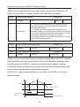
Explanation: control the output frequency through terminal FIV/ FC
(0~10V).
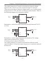
MV100
Power
supply
0-10V
R
S
T
U
V
W
+10V
FIV
GND
E
M
Motor
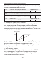
Explanation: control output frequency of inverter by FIV voltage
signal sent by external POT (10k Ω)
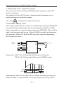
2: Analog current mode (0~20mA DC)
The output frequency of inverter is decided by external current
signal (0-20mA). Control the output frequency of inverter by external
terminal FIC.
MV100
R
S
T
Power
supply
0-20mA
U
V
W
FIC
GND
·47·
E
M
Earth
Motor
Operation Instruction of MV100 Series Inverter
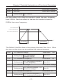
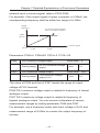
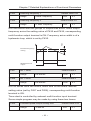
3: Setting dial mode (Operation panel)
You can control the running of H3400 series inverter by the POT
knob on Keypad.
Pay attention to the POT knob in Keypad which enables you to
switch between monitoring images.
Turn the
change the output frequency
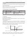
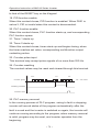
4 UP/DOWN setting mode
The output frequency of inverter is controlled by external UP/DOWN
terminals. External terminals can be selected from P315 to P322 ,
been selected one of external terminals as UP/DOWN. When UP is
valid, the frequency will go up. When DOWN is valid, the frequency
will go down. When UP and DOWN are both valid, the frequency
will remain the same.
MV100
R
S
T
Power
supply
UP
S1
Down S2
GND
U
V
W
M
Motor
E
Parameter: P317=15, S1 terminal will be set in UP mode.
P318=16, S2 terminal will be set in DOWN mode.
F
T
Run
Up
Down
Explanation: when UP is valid (UP is closed), frequency will go up.
When DOWN is valid (DOWN is closed), frequency will go down.
·48·
Chapter 7 Detailed Explanations of Functional Parameters
P102
Start signal selection
Initial value : 0
Setting range
0-2
Unit
1
Explanation
0: Operation panel (FWD/REV/STOP)
1: I/O terminal
2: Communication (RS485)
Start signal selection are used to set running signal source.
0: Operation panel (FWD/REV/STOP)
Operation panel gives the running signal. The running of inverter
” key (Forward reverse) key on the
can be controlled by the “
operation panel. Press “ ” key to stop running of inverter.
1: I/O terminal
In the initial setting ,the forward/reverse rotation signals are used
as start and stop signals .Turn on either of the forward and reverse
rotation signals to start the motor in the corresponding direction.
If both are turned off ( or on) during operation , the inverter
decelerates to a stop ( or Keep the original running condition )
You can make two-wire type or three-wire type control mode by
using I/O terminal
① Two-wire type
A two-wire type connection is shown below :
MV100
R
S
T
Power
supply
K1
K2
FWD
REV
GND
Parameter: P102=1 P315=6
U
V
W
E
P316=7
Operation Instruction of NT3000 Series Inverter
Actuating explanation:
·49·
M
Motor
Operation Instruction of MV100 Series Inverter
Input Status
Status of inverter
K1
K2
ON
OFF
Forward
OFF
OFF
Stop
OFF
ON
Reverse
ON
ON
Keep the original running condition
② Three-wire type
A three-wire type connection is shown below.
The start self-holding selection becomes valid when the STOP
signal is turned on. In this case, the forward/reverse rotation signal
functions only as a start signal.
If the start signal (S1/S2) is turned on and then off, the start signal
is held and makes a start. When changing the direction of rotation,
turn S1(S2) on once and then off.
The stop the inverter, turning off the STOP signal once decelerates
it to a stop.
MV100
R
S
T
Power
supply
Sw3
Sw1
Sw2
U
V
W
M
S1
S2
E
S3
GND
Use S1, S2, or S3 as input terminal for external signal
Parameter: P317=6 S1 is in forward
P318=7 S2 is in reverse
P319=9 S3 is in stop mode
P102=1 external terminal input
·50·
Motor
Chapter 7 Detailed Explanations of Functional Parameters
Output frequency
Time
Sw1
Sw2
Sw3
2: RS485 mode
Inverter can receive command and exchange data with computer by
serial communication.
P103
“stop” key lock operation selection
nitial value : 1
Setting range
0-1
Unit
Explanation
0: “Stop”key lock mode invalid
1: “Stop” key lock mode valid
1
The “STOP"key operation of the operation panel can be made
invalid to prevent unexpected stop.
Set “0” in P103,then press “ENTER” for 2s to make the “STOP” key
operation invalid, and “STOP” key can not stop running of inverter
Set “1” in P103,then press “ENTER” for 2s to make the “STOP” key
operation valid, and “STOP” key can stop running of inverter
MV100
R
S
T
Power
supply
K1
U
V
W
M
Motor
REV
GND
Procedure
1
Input
Explanation
K1 close
Reverse of inverter is started
·51·
Operation Instruction of MV100 Series Inverter
2
(K1 open) press stop key
Inverter stops
3
K1 open
Running signal is removed
4
K1 close
Reverse of inverter is started
P104
Reverse prevention setting
Setting range
0-1
Explanation
0: Reverse prohibited
1: Reverse allowed
Initial value : 1
Unit
1
Many devices only allow rotation in single direction. In this case,
you can set the machine in single rotation mode by this parameter.
0: Reverse prohibited
Reverse of motor is prohibited. When P104 is set at reverse
prohibited, switch between Forward and reverse is invalid.
1: Reverse allowed
Reverse of motor is enabled, switching between forward and
reverse is valid.
P105
Max. frequency
Setting range
Initial value: 50.00
Min. output frequency ~ 400.00Hz
The output frequency range of inverter is 0.1~400.00Hz. Therefore,
inverter can drive the motor higher than 50/60Hz, which could cause
mechanical damage or accident.
This parameter is to limit the inverter output frequency in order to
prevent motor operating at too higher speed.
P106
Min. frequency
Setting range
Initial value: 0.00
0.00 ~ max. frequency
This parameter is to set the minimum output frequency of the inverter.
If the setting frequency is lower than the Min. frequency, inverter
will output on the Min. frequency. In some application, this function
could avoid motor overheating due to the low speed operation.
·52·
Chapter 7 Detailed Explanations of Functional Parameters
P107
Acc time
Initial value: change
P108
Dec time
Initial value: change
Setting range
0.1~999.9s
Acc time refers to the time for inverter to reach the max. frequency
from 0.00Hz. Dec time refers to the time for inverter to lower to
0.00Hz from max. frequency.
F
P105Maximum
running frequency
Set running frequency
Accelerating
Decelerating
P107
P108
T
The Default Acc/Dec time is the primary Acc time/ Dec. time. Other
Acc time or Dec time can be selected via external terminal.
P109
V/F maximum voltage
Setting range
P110
V/F fundamental frequency
Setting range
P111
V/F intermediate frequency
~ max. frequency
V/F intermediate voltage
Setting range
P112
Initial value : 380
V/F intermediate
voltage~500.00
V/F minimum voltage ~ V/F
maximum voltage
V/F intermediate frequency
Setting range
V/F minimum frequency ~
V/F fundamental frequency
·53·
Unit 0.01
Initial value :
50
Unit 0.01
Initial value : change
Unit 0.1
Initial value : 2.5
Unit 0.01
Operation Instruction of MV100 Series Inverter
P113
V/F minimum voltage
Setting range
P114
Initial value : 15
0.0 ~ V/F intermediate
voltage
V/F minimum frequency
Setting range
Unit 0.1
Initial value : 1.25
0.0 ~ V/F intermediate
frequency
Unit 0.01
Parameters from P109 to P114 determine the V/F curve of inverter.
Set corresponding V/F curves according to different loads.
Constant torque curve: application for constant torque load, output
voltage and output frequency are in linear relation.
Down (variable) torque curve: application for variable torque load,
like fan and pump. Load will increase with the increase of rotation
speed.
High start torque curve: application for heavy load and load need
high starting torque.
V
High starting torque curve
P109
Constant torque curve
P111
Torque dropping curve
P113
P114
P112
P110
P105
F
P109: V/F maximum voltage, V/F maximum voltage can be set
according to the motor connected. Generally, it will be set at the
rated voltage of motor. When motor is very near to inverter, usually
within 30m, it should be set at a higher value.
P110: V/F fundamental frequency
V/F fundamental frequency, please set it at the running voltage
frequency of motor. Generally, do not change V/F fundamental
frequency setting; or else, it is very likely to damage motor.
P111: V/F intermediate voltage
·54·
Chapter 7 Detailed Explanations of Functional Parameters
Set V/F intermediate voltage according to the specific load. Improper
setup can cause over current of motor or insufficient torque output,
or even cause inverter protection. Increasing the value of P111 can
increase output torque and output current. Please monitor output
current while changing the value of P111. While changing the value
of P111, adjust the value slowly until the necessary output torque is
reached. Too higher setting may cause inverter protection or fault.
P112: V/F intermediate frequency
V/F intermediate frequency determines the intermediate point of V/F
curve. Improper setup can cause insufficient torque or over current
protection of inverter. Generally, do not change the setup value of
this parameter while using.
P113: V/F minimum voltage
V/F minimum voltage setup is relevant to start torque to a certain
extend. Increasing the value of this parameter properly can increase
the torque of starting, it can also cause over current. Generally, it’s
not necessary to change the value of P113.
P114: V/F minimum frequency
V/F minimum frequency determines the initial point of V/F curve, it
is the minimum value in V/F curve.
Please refer to the following table for the specific Default setting of
each model:
parameter
P107
P108
P111
P115
MV100-2S-0004-G
7
7
15
10
MV100-2S-0007-G
8
8
14
10
MV100-2S-0015-G
9
9
14
9
MV100-4T-0007-G
8
8
27
5
MV100-4T-0015-G
9
9
26
5
MV100-4T-0022-G
10
10
25
5
Model
·55·
Operation Instruction of MV100 Series Inverter
P115
Carrier frequency
Setting range
Factory Setting
1-15
unit 1
Carrier frequency decides the switching frequency of internal power
module. The factory setting of inverters with different capacity
are different because will affect motor noise, motor heating and
disturbance.
Carrier frequency P115
Motor Noise
Motor Heating
Disturbance
Small → Big
Big → Small
Small → Big
Small → Big
Therefore, when the environment demands running without noise,
you shall increase the value of P115, the maximum load of inverter will
decrease. If motor is far from inverter, you shall lower the value of P115
so as to lower the leakage current between wires and wire to ground.
When the environment temperature or motor load is high, you shall
lower the value of P115 to reduce the heating of the inverter. Refer
to table in P114 for the factory set of P115.
P117
Initialization of parameters
Initial value : 0
Setting range 0-8
Unit: 1
Explanation
8: Initialization of parameters
When the parameter setup is not proper or when false running leads
to improper setup of parameter, you can set P117 at 08 to restore all
parameters to the Factory Setting, and then you can set them again
according to actual need.
Attention: when locked up of parameters is valid, that is when
P118=1, you cannot carry out initialization of parameters and
change them. Please unlock first, and then set these parameters.
P118
Initialization of parameters
Setting range 0-1
Unit: 1
Explanation
0: Unlocked
·56·
Initial value: 0
Chapter 7 Detailed Explanations of Functional Parameters
1: Locked
You can lock the parameter by P118 to prevent unexpected change
of the inverter setup.
When P118 is valid, all the other parameters except P100 (main
frequency setting) cannot be changed.
7-3 Parameters of basic applications
P200
Start mode selection
Setting range
0-1
Explanation
Initial value : 0
Unit
1
0: Start at start frequency
1: Tracing start
There are two start modes for MV100 series inverter. You can
choose from the two by setup of parameter P200 and the condition
of machinery.
0: Start at start frequency
Most loads do not have special requirement in start. Inverter output
from the start frequency.
1: Tracing start
Tracing start is application for start after fault reset or instantaneous
power failure. Using tracing start function, inverter can automatically
detect the rotation speed and rotation direction of motor, the output
the starting frequency and voltage accordingly.
Motor speed
Frequency converter
output frequency
Running command
Attention: when inverter starts in tracing start mode, inverter will
have speed tracing in the sequence of high to low frequency.
·57·
Operation Instruction of MV100 Series Inverter
High current is likely in start, it is also possible to cause current.
Therefore, you need to have over current level setup (4.09 setup).
The specific value depends on the load.
In addition, when the value of 4.09 is too low, it may lead to a long
start time. If over current in the speed tracing, inverter will pause the
speed tracing.
P201
Stop mode selection
Initial value : 0
Setting range
0-1
Unit
Explanation
0: Deceleration to stop
1: Coasting stop
1
You can choose a suitable stop mode according to the actual load.
0: Deceleration to stop
Once inverter receives stop command, it will reduce the output
frequency according to the deceleration time.
F
Running
frequency
Shutdown
frequency
Free running shutdown
Shutdown duration
DC braking
With regard to stop mode after stop frequency is reached, you can
choose DC injection brake and other options. If you do not choose
DC injection braking, it will stop in coasting stop mode.
1: Coasting stop
When inverter receives stop command, it will stop frequency output
and it will have free running with load until it stops.
P202
Start frequency setting
Setting range
Initial value : 0.5
0.10-10.00
·58·
Unit
0.01
Chapter 7 Detailed Explanations of Functional Parameters
F
Set frequency
Startup
frequency
t
Running
command
Start frequency is the initial frequency when inverter starts. For
device with heavy load or requires large starting torque, increasing
start frequency can make start easier. However, if the start
frequency is too high, it may cause over current protection.
P203
Stop frequency setting
Setting range
Initial value : 0.5Hz
0.10-10.00Hz
Unit
0.01Hz
When inverter receives stop command, it reduce the output
frequency until the stop frequency, then it will start coasting stop or
DC injection brake stop according to the setting.
F
Running
frequency
Decelerating stop
DC braking stop
Shutdown
frequency
P204
Dc braking current in start
Setting range
P205
Free running stop
t
0-150
Dc braking time in start
Setting range
Initial value : 100
Unit
1
Unit
1
Initial value : 0
0-250
Dc braking in start is application for fan in stop mode and moving
load. Because before inverter starts, motor is in free running mode
·59·
Operation Instruction of MV100 Series Inverter
and the rotation direction is unknown. It is easy to cause over
current protection in start. Therefore, before start, you shall use DC
injection brake to stop the motor in advance.
Dc braking current in start is the ratio of rated current of inverter,
adjusting P204 can have different braking torques. While setting
value of parameter, you can adjust it from low to high until a
sufficient braking torque is reached according to the actual load.
Dc braking time is the period DC injection brake lasts. When it is 0,
DC injection brake is invalid.
P202
P205
Running
command
P206
Dc braking current in stop
Setting range
P207
Dc braking time in stop
Setting range
Initial value : 100
0-150
Unit
1
Unit
1
Initial value : 0
0-250
Dc braking in stop is application for load which has requirement on
braking.
Dc braking current in stop is the ratio of rated current of inverter.
Adjusting this parameter can have different braking torques.
Dc braking time in stop is the period DC injection brake mode lasts.
When it is 0, DC injection brake is invalid.
Refer to the explanations of P203, P204 and P205 for relevant
details.
P208
Torque boost
Setting range
Initial value : 5%
0.1-20%
·60·
Unit
0.1
Chapter 7 Detailed Explanations of Functional Parameters
Adjusting parameter P208 can increase voltage and obtain higher
torque.
Attention: Too big setting may cause motor overheating. Increase
the setting step by step until you get the requested starting torque.
V
100%
Torque
compensation
P209
Rated motor voltage
Setting range
P210
F
Initial value : 380.00V
0-500.00
Rated Motor current
P212
0-6000
0-10
Setting range
1
Initial value : 1420
Unit
1
Initial value : 4
Unit
Rated motor slip
0. 1
Initial value : 40
Unit
Numher of motor poles
Setting range
P214
0-100
Rated motor rotation speed
Setting range
P213
Unit
No load current ratio of motor
Setting range
0.01
Initial value : *
Setting range
P211
Unit
1
Initial value : 2.5
0-100
Unit
0. 1
Please set above parameters according to the motor rating.
P209 Rated voltage motor
Please set rated voltage of motor according to voltage value on
motor nameplate.
·61·
Operation Instruction of MV100 Series Inverter
P210 Rated motor current
Please set rated current of motor according to the current value on
nameplate. If the running current exceeds the value of rated current,
inverter will trip to protect the motor.
P211 No load current ratio of motor
The value of rated no load current of motor can affect slip
compensation. Rated no load current is the percentage of motor
current.
P212 Rated motor rotation speed
The value of parameter P112 is the rotation speed at 50Hz. It is
related to rotation speed display. Generally, it shall be set according
to the value on nameplate.
To display the actual rotation speed of motor, you can set parameter
P212 at the actual rotation speed at 50Hz.
P213 Number of motor poles
Set the number of pole pairs of motor by adjusting this parameter
according to the value on nameplate
P214 Rated motor slip
When inverter drives motor, slip will increase when load increase.
Adjusting P214 can compensation the slip and make motor speed
close to the synchronization speed.
P215
Rated motor frequency
Setting range
P216
Resistance of stator
Setting range
P217
Unit
0.01
Initial value: 0
0-100.00
Resistance of rotor
Setting range
P218
0.00-400.00
Initial value: 50Hz
Unit
0.01
Initial value: 0
0-100.00
Self inductance of rotor
·62·
Unit
0.01
Initial value: 0
Chapter 7 Detailed Explanations of Functional Parameters
Setting range
P219
0-1.000
Mutual inductance of rotor
Setting range
0-1.000
Unit
0.001
Initial value: 0
Unit
0.001
The above parameters are parameters of motor.
P215 Rated frequency of motor
Please set rated frequency of motor according to motor nameplate.
P216 Resistance of stator
P217 Resistance of rotor
P218 Self inductance of rotor
P219 Mutual inductance of rotor
Set the above parameters according to the actual condition of
motor.
7-4 Parameters for input and output application
P300
FIV minimum voltage input
Setting range
P301
FIV maximum voltage input
Setting range
P302
0~FIV maximum voltage
input
FIV minimum voltage
input~0
FIV input filter time
Setting range
Initial value: 0
Unit
0.1
Initial value: 10.0
Unit
0.1
Initial value: 1.0
0-25.0
Unit
1
P300 FIV minimum voltage input
FIV minimum voltage input value is related to frequency of lowest
analogue input. Voltage command below this value is deemed as
invalid command.
P301 FIV maximum voltage input
FIV maximum voltage input value is related to frequency of highest
analogue input. For voltage higher than this value, the machine will
·63·
Operation Instruction of MV100 Series Inverter
still operate at this value.
The value of P300 and that of P301 decide the range of input
voltage.
P302 Input filter time
Value of input filter time decides the response speed of inverter to
analogue change. With the increase of value of P302, the inverter
will get slower for responding to analogue change.
P303
FIC minimum current input
Setting range
P304
FIC maximum current input
Setting range
P305
0~FIC maximum current
input
FIC minimum current
input-20.0
FIC input filter time
Setting range
Initial value: 0
Unit
0.1
Initial value: 20.0
Unit
0.1
Initial value: 1.0
0-25.0
Unit
0.1
P303: FIC minimum current input
FIC minimum current input is related to frequency of lowest
analogue input. Inverter will deem current signal below value of
P303 as invalid.
P304: FIC maximum current input
FIC maximum current input is related to frequency of highest
analogue input. For current command higher than value of P304,
inverter will operate at the value.
P305: FIC input filter time
FIC input filter time decides how fast inverter responds to analogue
change. With the increase of value of P305, inverter will respond
more and more slowly to analogue change. The output of inverter
will be relatively stable.
Refer to explanations of P300 to P302 for relevant parameters.
If the external input is voltage signal, refer to P300-P302. If the
·64·
Chapter 7 Detailed Explanations of Functional Parameters
external input is current signal, refer to P303-P305.
For example, if the output signal of upper computer is 4-20mA, the
corresponding frequency shall be within the range of 0–50Hz.
Output
frequency
A current signal of 20mA
above is treated sa 20mA
50Hz
(P312)
0
(P310)
4 mA
P303
20 mA
P304
Current signal
Parameters: P303=4 P304=20 P310= 0 P312= 50
P306
FOV minimum voltage output
Setting range
P307
0-FOV maximum voltage
output
FOV maximum voltage output
Setting range
FOV minimum voltage
output-10.0
Initial value : 0
Unit
0.1
Initial value : 10.0
Unit
0.1
The value of P306 and that of P307 decide the range of output
voltage of FOV terminal.
P306 FOV minimum voltage output is related to frequency of lowest
analogue output.
P307 FOV maximum voltage output is related to frequency of
highest analogue output. You can connect voltmeters of various
measurement ranges by setting parameter P306 and P307.
For example, use a frequency meter with input voltage of 0-5V and
measurement range of 0-50Hz to monitor the output frequency of
inverter.
·65·
Operation Instruction of MV100 Series Inverter
V
P307
5V
P306
0V 0
50Hz
P312
P310
F
Then you need to set them like the following: P306-P307=5.
P308
FOC minimum current output
Setting range
P309
0-FOC maximum current
output
FOC maximum current output
Setting range
FOC minimum current
output-20.0
Initial value : 0
Unit
0.1
Initial value : 20.0
Unit
0.1
P308 and P309 decides the range of output current of FOC terminal.
P308 and P309 correspond to frequency of lowest analogue output
and frequency of highest analogue output respectively. Refer to
explanations of P306 and P307 for relevant parameters.
P310
Frequency of low analog
Setting range
P311
P312
Direction of of low analog
Setting range
0-1
Explanation
0: Positive direction
1: Negative direction
0.00-600.00
Direction of high analog
Setting range
Unit
0-1
1
Initial value: 50
Unit
0.01
Initial value: 0
Unit
·66·
0.01
Initial value: 0
Unit
Frequency of high analog
Setting range
P313
0.0-600.00
Initial value: 0.00
1
Chapter 7 Detailed Explanations of Functional Parameters
Explanation
P314
0: Positive direction
1: Negative direction
Analogue reverse options
Initial value: 0
Setting range
0-1
Unit
1
Explanation
0: No reverse at negative bias voltage
1: Reverse allowed at negative bias voltage
The parameter group of P310-P314 decides the running condition
of analogue, including output frequency and direction. According to
actual need of user, they can form various control curves.
P310 Frequency of low analog
Frequency of lower analogue decides the output frequency of
lowest analogue input, corresponding to analogue minimum voltage
(current) input.
P311 Direction of low analog
Direction of lower analogue decides the running condition at low
frequency, whether it is Forward or reverse.
P312 Frequency of high analog
Analogue high-end frequency determines high-end output
frequency, and is corresponding to analogue maximum voltage
(current) input.
P313 Direction of high analog
Analogue high-end direction determines whether the running status
of high-end frequency is forward or reverse.
P314 Analog input reverse selection
Analogue reverse selection determines running status of analog
negative bias voltage, satisfied curve needed by customer can be
constituted by using above parameter.
Example 1: upper computer output 2-10 V signal to control inverter,
50Hz reverse to 50Hz forward running.
·67·
Operation Instruction of MV100 Series Inverter
F
P312
50Hz
0
2
6
V
10
P300
P310
P310
50
Introduction: P300=2 FIV minimum voltage input: 2V (inverter
regards signals below 2V as invalid signals);
P301=10 FIV maximum voltage input: 10V (signals over 10V are
regarded and handled as 10V);
P310=50 Analogue low-end frequency: 50Hz;
P311=1 Analogue low-end direction: 1 (reverse);
P312=50 Analogue high-end frequency: 50Hz;
P313=0 Analogue high-end direction: 0 (Forward);
P314=1 Analogue reverse selection: 1 (negative bias voltage can be
reversed).
Attention: In various curves, switching instructions of forward and
reverse remain effective, when forward and reverse are switched,
the curve will be reversed, and the diagram of curve is as follows:
F
50Hz
2
6
50Hz
·68·
10
V
Chapter 7 Detailed Explanations of Functional Parameters
Example 2, upper computer output 4-20mA, and controls running of
inverter Output frequency is 100Hz-0Hz
P310
100Hz
P312
0
4(P303)
20(P304)
Signal
Parameter: P33=4 FIC minimum current input
P304=20 FIC maximum current input
P310=100.00 analogue low-end frequency
P311=0 analogue low-end direction (Forward)
P312=0 analogue high-end frequency
P314=0 analogue high-end direction (Forward)
Special inverted curve can be constituted by using P310-P314.
Introduction: signal input below 4mA is regarded as invalid signal by
inverter.
P315
Multifunction input terminal---FWD terminal
Default value 6
P316
Multifunction input terminal---REV terminal
Default value 7
P317
Multifunction input terminal---S1 terminal
Default value 1
P318
Multifunction input terminal---S2 terminal
Default value 18
P319
Multifunction input terminal---S3 terminal
Default value 15
P320
Multifunction input terminal---S4 terminal
Default value 16
P321
Multifunction input terminal---S5 terminal
Default value 8
P322
Multifunction input terminal---S6 terminal
Default value 9
Range
0-32
·69·
Unit
1
Operation Instruction of MV100 Series Inverter
Settings
0: Invalid
1: Jog
2: Jog Forward
3: Jog reverse
4: Forward/ reverse
5: Running
6: Forward
7: Reverse
8: Stop
9: Multi-speed selection 1
10: Multi-speed selection 2
11: Multi-speed selection 3
12: Multi-speed selection 4
13: Acceleration/ deceleration selection 1
14: Acceleration/ deceleration selection 2
15: Frequency increasing signal Up
16: Frequency decreasing signal Down
17: Coasting stop
18: Fault reset
19: PID function enable
20: PLC function enable
21: Timer 1 start up
22: Timer 2 start up
23: Counter pulse input
24: Counter reset
25: PLC memory clear
26: Winding operation start
0: Invalid
Set as empty terminal, no function
1: Jog
Set as JOG (inching), usually used in trial running, common inching
is operated by 5Hz,
2: Jog Forward
Set as JOG forward.
3: Jog reverse
Set as JOG reverse.
4: Forward/ reverse
·70·
Chapter 7 Detailed Explanations of Functional Parameters
Set as forward/ reverse switching, when the terminal is defined to
be valid, running status reverse.
MV100
U
V
W
R
S
T
FWD
REV
GND
M
Motor
E
Parameter: P102=1, P315=6, P316=4
Terminal status
Running condition
FWD
REV
ON
OFF
Forward
ON
ON
Reverse
OFF
OFF
Stop
5: Running
Set terminal as running signal.
6: Forward
When terminal is valid, motor run forward.
7: Reverse
When terminal is valid, motor run reverse.
8: Stop
When terminal is valid, motor run reverse.
9: Multi-speed 1
10: Multi-speed 2
11: Multi-speed 3
12: Multi-speed 4
15-speed can be selected by terminal multi-speed 1, 2, 3 and 4 as
below table:
·71·
Operation Instruction of MV100 Series Inverter
Multi-function terminal
Multi- Multi-speed Multi-speed
speed 1
2
3
Multispeed 4
Status and explanation
0
0
0
0
Primary frequency, Primary
frequency is determined by
P100 or potentiometer
1
0
0
0
Multi-speed 1 (P503)
0
1
0
0
Multi-speed 2 (P504)
0
0
1
0
Multi-speed 3(P505)
0
0
0
1
Multi-speed 4 (P506)
1
1
0
0
Multi-speed 5 (P507)
1
0
1
0
Multi-speed 6 (P508)
1
0
0
1
Multispeed 7(P509)
0
1
1
0
Multi-speed 8 (P510)
0
1
0
1
Multi-speed 9 (P511)
0
0
1
1
Multi-speed 10 (P512)
1
1
1
0
Multi-speed 11 (P513)
1
1
0
1
Multi-speed 12 (P514)
1
0
1
1
Multi-speed 13 (P515)
0
1
1
1
Multi-speed 14 (P516)
1
1
1
1
Multi-speed 15 (P517)
Remarks: 0: terminal invalid 1: terminal invalid
13: acceleration / deceleration selection 1
14: acceleration / deceleration selection 2
4 kinds of acceleration / deceleration times can be selected by
acceleration / deceleration selection terminal 1and 2.
Multi-function terminal
Acceleration/
deceleration
selection 1
Acceleration/
deceleration
selection 2
Acceleration / deceleration status
and result
·72·
Chapter 7 Detailed Explanations of Functional Parameters
0
0
Acceleration/ deceleration time 1
(P107, P108)
1
0
Acceleration/ deceleration time 2
(P401, P402)
0
1
Acceleration/ deceleration time 3
(P403, P404)
1
1
Acceleration/ deceleration time 4
(P405, P406)
15. Frequency increasing signal (Up signal)
When this terminal is valid, the frequency increases at a constant
speed, until operative frequency is highest.
16. Frequency decreasing signal (Down signal)
When this terminal is valid, the frequency decreases at a constant
speed, until operative frequency is lowest.
Attention: Inverter will not memorize the frequency setting changed
by “UP” and “DOWN” signal. When power is turned off and reset
again, inverter still memorizes the set value in P100.
Frequency
Max. running
frequency
Set frequency
Min, running frequency
Time
Running command
UP command
Down command
17: Coasting stop
When this terminal is valid, inverter coasting to stop.
18. Fault reset
Reset the inverter when alarm occurs, this terminal function is same
·73·
Operation Instruction of MV100 Series Inverter
to that of the RESET key on the Keypad.
19. PID function enable
When this contact closes, PID function is enabled. When P601 is
set as 2, PID is invalid when this contact is disconnected.
20. PLC function enable
When this contact closes, PLC function starts up, and corresponding
PLC function opens.
21. Timer 1 starts up
22. Timer 2 starts up
When this contact closes, timer starts up and begins timing, when
the timer reaches set value, corresponding multifunction output
contacting action.
23. Counter pulse input
This terminal may accept pulse signals of no more than 250 Hz.
24. Counter resetting
The counted values may be reset and cleared through this terminal.
Coo
Cn
Co
Cn = set count
Counter pulse
Counting reached
Counter reset
25. PLC memory removal
In the running process of PLC program, owing to fault or stopping,
inverter will record status of the program automatically, after the
fault is cured and the inverter is switched on again, the inverter will
continue running according to the program, when memory removal
is valid, program may be reset, and inverter operates from the
beginning.
·74·
Chapter 7 Detailed Explanations of Functional Parameters
Programmed operation
Time
PLC controlled
operation
Running signal
PLC memory cleared
26. Winding function enable
When this signal is valid, winding function is enabled.
Frequency
Set frequency
Time
Running command
Winding started
Winding completed
Introduction:
① Winding function is activated, and winding begins;
② Winding operation complete, inverter output according to the
frequency that winding is completed. The multifunction terminal
output the winding complete signal;
③ Inverter stops, the winding complete signal reset.
P323
Output terminal M01
Default value 01
P324
Output terminal M02
Default value 02
P325
Output terminal YA, YB, YC
Default value 03
Range
0-32
·75·
Unit
1
Operation Instruction of MV100 Series Inverter
Setting
0: Invalid
1: In running
2: Frequency reached
3: In fault
4: Zero-speed
5: Frequency 1 reached
6: Frequency 2 reached
7: Accelerating
8: Decelerating
9: Under voltage
10: Timer 1 reached
11: Timer 2 reached
12: Indication for completion of phase
13: Indication for completion of procedure
14: PID upper limit
15: PID lower limit
16: 4-20mA cable open
17: Overload
18: Over torque
26: Winding function complete
27: Counter reached
28: Intermediate counter reached
0: Invalid
Set as invalid terminal, prevent false operation.
1. In running
Terminal is defined to be in running, when inverter is output, this
terminal is ON.
2. Frequency reached
When frequency arrives at setting value, this contact is ON
3. In fault
When inverter detects abnormal existing, this contact is ON.
4. Zero-speed
When frequency output by inverter is less than start-up frequency, this
contact is ON.
5. Frequency 1 reached
6. frequency 2 reached
When frequency arrives at setting value, this contact is ON.
·76·
Chapter 7 Detailed Explanations of Functional Parameters
Frequency
Set running
frequency
Cofrequency
range
Set reached
frequency
Time
Running command
Multifunctional
output terminal
7: Accelerating
When inverter is in the status of accelerating, this contact is ON.
8: Decelerating
When inverter is in the status of decelerating, this contact is ON.
Frequency
Time
Running command
Accelerating
Decelerating
9. Under voltage alarming
When inverter detects that DC bus voltage is lower than setting
value, this contact is ON and alarm. Under voltage alarming setting
value can be changed through advanced application parameter
group.
·77·
Operation Instruction of MV100 Series Inverter
10: Timer 1 reached
11: Timer 2 reached
When inverter arrives at setting value, this contact is ON, when
timer start-up signal is removed, this contact is reset.
12: Stage completion indication
In the PLC operation mode, inverter output this pulse signal when
inverter finished a section of program.
Program setting: stop after
three cycles of operation
Running command
Stage completion indicating
Process commpletion
indicating
13. Process completion indication
In the PLC operation mode, inverter output this pulse signal when
inverter finished the entire program.
14. PID upper limit
When PID feedback quantity exceeds setting value of upper limit,
this contact is ON.
15: PID lower limit
When PID feedback quantity is lower than setting value, this contact
is ON.
16: 4-20mA cable open
When FIC input signal is disconnected, this contact is ON and
alarms.
17: Overload detection
When inverter detects that motor overloads, this contact is ON.
18: Over torque detection
When inverter detects over torque, this contact is ON.
26: Winding function complete
·78·
Chapter 7 Detailed Explanations of Functional Parameters
When winding function is complete, this contact is ON. When
inverter stops, this contact is reset.
27: Set counter reached
When inverter implements external counter, and when count value
arrives at setting value (P425), this contact is ON.
28: Middle counter reached
When inverter counts, if count value arrives at setting value (P426),
this contact is ON.
P326
Output terminal FOV
Setting range
P327
Default value 0
0-7
Unit
Output terminal FOC
Setting
1
Default value 1
0: Output frequency
1: Output current
2: Direct voltage
3: Alternating voltage
P326 output terminal FOV
FOV terminal may output 0-10V voltage, output may be setting in
range of 0-10V through P306 and P307 and being corresponding to
output frequency, output current, direct voltage, alternating voltage
and so on.
P327 output terminal FOC
FOC terminal may output 0-20m current, output range may be
setting by P308 and P309 and being corresponding to output
frequency, output current, direct voltage, alternating voltage and so
on.
0: Output frequency:
Current (voltage) output is corresponding to Min. output
frequency~max. frequency.
1: Output current
Current (voltage) output is corresponding to 0~2 × inverter rated
current.
·79·
Operation Instruction of MV100 Series Inverter
2: Direct voltage
Current (voltage) output is corresponding to 0~1000V.
3: Alternating voltage
Current (voltage) output is corresponding to 0~510V.
For example: select a frequency meter of 0~5V, supervise output
frequency, setting the Min. output frequency of inverter as 0.00Hz,
the highest output frequency is 80Hz.
Then:
MV100
R
S
T
F
U
V
W
M
Modor
80Hz
FWD
GND
FOV
V
GND
E
0
5V
Parameter: P105=80.00 Max. frequency
P106=0.00 Min. output frequency
P306=0.00 FOV minimum voltage output
P307=5.00 FOV maximum voltage output
7-5 Secondary application group
P400
Jog frequency setting
Range
Default value 5.00
0.00---max. frequency
Unit
0.01
Jog frequency setting is usually applied to trial run. This function
can only be through external terminal.
When JOG function is achieved, other instruction is invalid. When
JOG signal is open, inverter decelerate to stop, JOG acceleration/
deceleration time is set in the 4th acceleration/ deceleration
parameter.
Control priority level:
·80·
V
Chapter 7 Detailed Explanations of Functional Parameters
Jog→ external multi-speed→PLC operation means→ PID means→
triangle wave (traverse function) → winding→ frequency conversion
setting means.
P401
Acceleration time 2
Default value 10.0
P402
Decelerate time 2
Default value 10.0
P403
Acceleration time 3
Default value 20.0
P404
Decelerate time 3
Default value 20.0
P405
Acceleration time 4
Default value 2.0
P406
Decelerate time 4
Default value 2.0
Range
0-999.9s
Unit
0.1
MV100 series inverters can set 4 acceleration / deceleration time.
For normal operation, the default selection is the acceleration /
deceleration time 1. For JOG operation, the default selection is
acceleration / deceleration time 4.
P407
Setting value of counter
Default value 100
P408
Middle value of counter
Default value 50
Range
0-999.9s
unit
1
MV100 series inverter designs 2 groups of counters, pulse signal
less than 250Hz can be accepted through multi-function terminal,
when count value reaches setting value, corresponding multifunction output terminal is ON, input terminal of counter resets
signal through counter, counter resets and begins counting again.
P409
Acceleration torque limiting level
Range
0-200
Default value 150
Unit
1
Parameter P409 is the torque limit level during acceleration.
When output current reaches the setting value, inverter will stop
accelerating, and when current is below the set value, inverter
resume the accelerating.
·81·
Operation Instruction of MV100 Series Inverter
Current
P409
Accelerating torque
limitation level
Output frequency
100% current is the rated current of inverter, when P409 is set to
be 0, then accelerating torque limit is invalid, and it does not have
protecting function.
P410
Constant-speed torque limiting level
Range
Default value 00
0-200
Unit
1
Parameter P409 is the torque limit level during constant speed. When
output current reaches the setting value, inverter automatically
reduce the output frequency in order to reduce the load. When
the output current drops, inverter increase output frequency to the
setting (100% current is rated current of inverter).
When P410 is set to be 0, constant-speed torque limiting level is
invalid and cannot protect.
Current
P410
Output frequency
P411
Deceleration over-voltage prevention selection
Range
0-1
Settings
0:Invalid
Default value 1
Unit
1:Valid
·82·
Chapter 7 Detailed Explanations of Functional Parameters
0: Invalid
During deceleration, the DC-bus voltage may increase, when overvoltage prevention selection is invalid, inverter may trip for over
voltage.
1: Valid
During deceleration, when DC-bus voltage reaches the setting
value, inverter will stop the deceleration procedure. When DCbus voltage returns to allowable value, inverter will resume the
deceleration.
Voltage
directrix
DC voltage
Output frequency
Shutdown
command
P412
Automatic voltage regulation selection
Default value 1
Range
0-2
Unit
Settings
0: Invalid
1: Valid
2: Invalid when decelerating
1
If the input voltage is not stable, temperature of the machinery will
increase, insulation may be damaged, and output torque will be
instable.
0: Invalid
Select automatic voltage regulation to be invalid, inverter output
voltage fluctuates.
1: Automatic voltage regulation is valid.
Automatic voltage regulation function is selected, and under the
condition that input electric source is instable, inverter output stable
voltage automatically.
·83·
Operation Instruction of MV100 Series Inverter
2: Invalid when decelerating: when this function is selected, braking
function of inverter can be strengthened.
P413
Automatic energy-saving selection
Range
P414
0-100
Unit
1
DC Braking voltage
Default value:650V for H3400 / 375V for H3200
H3400 series: 650V~800V
H3200 series: 360V~400V
Range
P415
Default value 0.0
Braking duty
Range
Unit
1
Default value: 50
40-100
Unit
1
P413 Automatic energy-saving selection
In constant-speed running of automatic energy-saving selection,
best voltage value may be calculated by loading condition and
provided to load, in order to achieve best energy-saving.
Attention: for running that load changes frequently or is almost at full
load, this function is not suitable.
Output frequency
100%
F
P414 and P415 are only useful for inverter with built-in braking units,
and are invalid for inverter with external braking units.
The two parameters adjust internal DC braking voltage level and
braking ratio of inverter.
P414 DC Braking voltage
When inverter DC high voltage is higher than set value of P414,
built-in braking unit is ON. Energy is released through braking
resistor, then DC voltage falls back, when DC voltage falls to a
certain value, built-in braking unit stop.
·84·
Chapter 7 Detailed Explanations of Functional Parameters
Dc high pressure
50V
P414
DC high voltage
If P414 is too high, DC voltage may be too high and may cause
inverter protection.
If P414 is too low, braking resistor maybe too hot.
P415 Braking duty
This parameter decides the working duty of the braking resistor.
Higher duty needs high power of braking resistor.
P416
Restart after instant power off
Default value 0
Range
0-1
Unit
1
Settings
0: Invalid: no restart after instant power failure
1: Valid: frequency tracing start-up
0: Invalid
Inverter clears the running command after power failure. After power
is recovered, inverter will not start automatically.
1: Frequency tracing enable
When power is shut-off in short time, inverter keeps the running
command as effective. When power is recovered in time, inverter
will tracing the motor speed and resume output.
Attention: when instant power failure restarting is enabled, inverter
may start the motor automatically. Please take care of the safety
when use this function.
·85·
Operation Instruction of MV100 Series Inverter
MV100
Power
supply
U
V
W
R
S
T
M
Motor
FWD
GND
Example:
Use K1 (FWD), control running of inverter.
K1 closes, frequency conversion operates, when K1 is cut off,
inverter stops. When power is shut off and K1 remains closed,
if power is on, inverter starts up suddenly and it may be very
dangerous. Please use other control methods, such as three-wire
system connection method.
P417
Allowable time of power off
Range
Default value 5.0
0-10.0
unit
0.1
P417 sets allowable time of power failure, if time of power failure
exceeds set value, power failure restart is invalid.
P418
Flank restart current limiting level
Range
0-200
Default value 150
Unit
1
When inverter implements flying restart, inverter tracing downwards
from setting frequency by highest speed, output current of inverter
increases relatively rapid and may exceeds protection unit setting
by inverter, at this time, inverter stops tracing, and output current
of inverter falls back to common, inverter continues tracing, setting
value 100% of this parameter is rated current of inverter, and
protection unit when inverter searching may be set through P418.
·86·
Chapter 7 Detailed Explanations of Functional Parameters
P418
Output current
Output frequency
Motor speed
t
Actual overspeed starting time
P419
Flank restart time
Range
Default value 5
0-10
Unit
When inverter enabled the flying restart function, inverter tracing
motor speed downwards within the setting time. If it is not completed
within setting time, inverter protects.
In above example, when t value > P419 setting value, inverter
protects.
P420
Fault restart times
Range
P421
Default value 0
0-5
Unit
Delay time for restart after fault
Range
0-100
1
Default value 2
Unit
1
After alarm (such as current, over-voltage and so on) occurs,
inverter resets automatically (valid when non-zero as set by P420),
after the period of time set by P421, inverter starts up according to
setting start-up means (P200).
After start-up, if no alarm happens within 60 seconds, inverter resets
P420 automatically, after start-up,
If alarm happens again within 60 seconds, inverter records number
of alarms, and when number of alarms reaches set value of P420,
inverter stops output.
Attention: If P420=0, fault restart is invalid.
·87·
Operation Instruction of MV100 Series Inverter
When fault restart function is valid, motor may start suddenly, so
when this function is used, please pay attention to safety.
P422
P423
Over torque action
Range
0-3
Settings
0: Inverter start detecting over torque only in
constant speed, inverter continues operation
during over torque
1: Inverter start detecting over torque only in
constant speed, inverter stop during over torque
2: Inverter always detecting over torque, inverter
continues operation during over torque
3: Inverter always detecting over torque, inverter
stop during over torque
unit
Over torque detection level
Range
P424
Default 0
0-200%
Over torque detection time
Range
0-200s
1
Default 0
Minimum
1
Default 0
Minimum
1
When output current of inverter exceeds setting value of P423, inverter
start calculate the over torque time. When the duration exceeds half
of setting value of P424, inverter output pre-alarm signal. Inverter
continues output until the over torque time exceeds P424 setting, and
then inverter protects and output alarm signal.
If P423=0. over torque detection is invalid, and 100% is inverter
rated current.
P423
Torque curve
Overtorque
alarm
P424
2
Running state
·88·
Chapter 7 Detailed Explanations of Functional Parameters
P425
Reaching frequency 1
Range
P426
Default value 100
0-Max. frequency
Reaching frequency 2
Range
Unit
0.1
Default value 5.0
0- Max. frequency
Unit
0.1
MV100A series sets two groups of frequencies arrive, when output
frequency arrive the setting value of P425 and P426, corresponding
multi-function output terminal is ON. Frequency arrive width is of a
P430
hysteresis loop, which is set by P430.
Reached frequency
setting
Multifunctional
output
P427
No. 1 timer
Range
P428
Default value 0
0.0-999.9s
No. 2 timer
Range
Unit
0.1
Default value 0
0.0-999.9s
Unit
0.1
MV100 series have two timers, when time of the timers reaches
setting value (set by P427 and P428), corresponding multi-function
terminal is ON.
Timer start is controlled by external multi-function input terminal.
Some simple program may be made by using these two timers.
P429
Constant-speed torque limiting time
Range
0-999.9s
·89·
Default value 0.50
unit
0.1
Operation Instruction of MV100 Series Inverter
P430
Width of arrive of frequency in hqsteretic loop
Default value 0.50
Range
0.00-2.00
unit
0.01
This parameter sets frequency reached width, for details, refer to
P425-F426 introductions.
P431
Jump Frequency 1
Range
P432
0.00-frequency upper limit
Jump Frequency 2
Range
P433
Default value 0
0.01
Default value 0
0.00-frequency upper limit
Jump frequency hysteresis loop width
Range
unit
unit
0.01
Default value 0.50
0.00-2.00
unit
0.01
If machine resonance occurred at a certain frequency, we can
use the frequency jump function to skip the resonance point.
MV100A support 2 jump frequencies by parameter P431 and P432.
Frequency jump hysteresis loop width can be set through P433 as
P433
below:
P431
P432
7-6 Special operation (PLC Control)
P500
PLC memory mode
Initial value: 0
Range
0-1
Unit
Content:
0: Do not remember
1: Remember
1
·90·
Chapter 7 Detailed Explanations of Functional Parameters
0: Do not remember
In the operational process of PLC program, P500 will choose not
to remember. When machinery stops because of fault or other
reasons, inverter will not remember status before the stopping. After
restart, running begins from initial state.
1: Remember
In the running of PLC program, P500 will select to remember. When
it stops because of fault or other reasons, inverter will remember
status before stopping. After restart, inverter will continue operating
according to program. Attention: power cannot be cut off.
Stop,power cut and power on, inverter will not remember status
before power cut off. After restarting, inverter will run according to
initial state of program.
P501
PLC start mode
Initial value: 0
Range
0-1
Unit
Content:
0: Invalid (PLC can not start)
1: Valid (PLC start)
1
P501 determines PLC start mode of inverter.
P501=0, means PLC is invalid. The inverter is operated by common
mode.
When P501=1, PLC will start. The inverter select PLC program to
run.
Under the status of PLC start, when various running orders and
programs, inverter will choose the highest level to run according to
priority level.
Precedence level
High→ low
Priority level
Item
1
Jog
2
External multi-speed
3
Internal multi-speed
4
PID
·91·
Operation Instruction of MV100 Series Inverter
High→ low
P502
5
Triangular wave
6
Winding
7
Inverter setting mode
PLC running mode
Initial value: 0
Range
0-4
Unit
1
Content:
0: PLC stop running after a week
1: PLC pause mode, stop running after a week
2: PLC cycle running
3: Cycle running of PLC pause mode
4: After running for a week, PLC continues
running by the end of running frequency
PLC running mode determines running status of internal multispeed, either running one circle or cycle running. P502 is only valid
when PLC starts up.
PLC pause mode means that when completing every speed in the
running process of internal multi-speed, the speed will be down,
stop, and accelerate to the next speed. The illustration is as below:
Frequency
Time
Users may select proper running mode according to actual
conditions.
P503
Multi-speed 1
Initial value: 10.0
P504
Multi-speed 2
Initial value: 15.0
P505
Multi-speed 3
Initial value: 20.0
P506
Multi-speed 4
Initial value: 25.0
·92·
Chapter 7 Detailed Explanations of Functional Parameters
P507
Multi-speed 5
Initial value: 30.0
P508
Multi-speed 6
Initial value: 35.0
P509
Multi-speed 7
Initial value: 40.0
P510
Multi-speed 8
Initial value: 45.0
P511
Multi-speed 9
Initial value: 50.0
P512
Multi-speed 10
Initial value: 10.0
P513
Multi-speed 11
Initial value: 10.0
P514
Multi-speed 12
Initial value: 10.0
P515
Multi-speed 13
Initial value: 10.0
P516
Multi-speed 14
Initial value: 10.0
P517
Multi-speed 15
Initial value: 10.0
Setting range
0.00 ----- Max. frequency
Unit
0.01
P503 ----- P517 are set of 15 speed of rated frequency in the
running. Regarding relationship multi speed and external terminal
please refer to rated instruction 1,2,3,4 of multifunctional terminal.
P518
PLC operation time 1
Initial value: 100
P519
PLC operation time 2
Initial value: 100
P520
PLC operation time 3
Initial value: 100
P521
PLC operation time 4
Initial value: 100
P522
PLC operation time 5
Initial value: 100
P523
PLC operation time 6
Initial value: 0
P524
PLC operation time 7
Initial value: 0
P525
PLC operation time 8
Initial value: 0
P526
PLC operation time 9
Initial value: 0
P527
PLC operation time 10
Initial value: 0
P528
PLC operation time 11
Initial value: 0
·93·
Operation Instruction of MV100 Series Inverter
P529
PLC operation time 12
Initial value: 0
P530
PLC operation time 13
Initial value: 0
P531
PLC operation time 14
Initial value: 0
P532
PLC operation time 15
Initial value: 0
Setting range
0-999.9s
Unit
1
PLC operation time determines internal controlling varying rated
running duration for each segment, and the running duration for
each segment is corresponding to its rate.
P533
PLC operation time 15
Setting range
Initial value: 0
0-32767
Unit
1
P533 setting running direction of each segment
Method of setting running direction:
The way of setting running direction: by means of 16-bit binary
system, and then transfer to decimal system value; every bit decides
the corresponding running direction: 0 is running forward and 1 is
running backward, and this parameter is only valid when the PLC is
on.
For example: there is a five-segment rate, the circling running is
required as follow:
Items
Output frequency
Running direction
Running duration
Dominant
frequency
Potentiometer is
adjustable
Forward
Segment 1
20.0
Reverse
20
Segment 2
60.0
Forward
25
Segment 3
40.0
Reverse
30
Segment 4
15.0
Forward
20
Two buttons, one is for running, the other one is for ceasing; the
main frequency requires adjustable potentiometer.
·94·
Chapter 7 Detailed Explanations of Functional Parameters
R
S
T
Power
supply
MV100
U
V
W
M
Motor
+10V
10K
FIV
K2
K1
GND
S1
K3
S2
S3
E
GND
(1) Connection illustration
(2) Parameter setting
PLC operation direction setting: (P533 setting)
Rate of Rate of Rate of Rate of
Dominant
segment segment segment segment
frequency
1
2
3
4
4
3
2
1
0
→ position (bit)
0
1
0
1
0
→ run direction <0 is
forward, 1 is Reverse
0×24
1×23
0×22
1×21
0×20
→ transfer to decimal
system
The binary system number 01010 is transferred to decimal system
number: 1×21+1×23+8=10
Define to: P533=10
The parameter defines to:
P101=3
(Keyboard potentiometer setting mode: dominant
frequency is controlled by potentiometer)
P102=2
(Running setting option: Multifunction end input)
P105=60
(The max. frequency is 60HZ)
P107=10
P108=10 (acceleration/deceleration time 10S)
P314=6
(S1 end is running forward)
P318=8
(S2 end is ceasing)
·95·
Operation Instruction of MV100 Series Inverter
P319=20
S3 end is PLC starting to running
P500=1
PLC programming memory
P501=1
PLC is on
P502=0
PLC operation one circle and then ceasing
P503=1
Segment 1 rated 20Hz
P504=60
Segment 1 rated 60Hz
P505=40
Segment 1 rated 40Hz
P506=15
Segment 1 rated 15Hz
P518=10
Segment 1 rated running duration is 10s
P519=20
Segment 1 rated running duration is 20s
P520=25
Segment 1 rated running duration is 25s
P521=30
Segment 1 rated running duration is 30s
Shutdown
Frequency
25S
60
Converter control
20S
15
Time
20
20S
30S
40
K2
K3
K1
Action instruction: ① Press K1 to startup the inverter and the
potentiometer will set output frequency.
② Press K3, PLC to startup, and from the
segment 1 PLC program running one circle
and then ceasing
·96·
Chapter 7 Detailed Explanations of Functional Parameters
③ If the program is running, press K3, or if there
is a fault, and the inverter is ceasing, when the
fault is solved, press K1 and the inverter will
running forward as the program.
④ If P500 is 1 and the program is not memory, so
the running will start from the very beginning.
F
P503
P517
P504
P518
T
P519
7-7 Special operation (PID Control)
The inverter can be used to exercise process control, e.g. flow rate,
air volume or pressue.
The terminal FIV/FIC input signal or parameter setting is used as a
set point and the terminal FIV/FIC input signal also can used as a
feedback value to constitute a feedback system for PID control.
P600
PID starting mode
Initial value: 0
Setting range
0-1
Content:
0: PID disable
1: PID start
2: PID start by external terminal
Unit
1
0: PID disable
PID can not use.
1: PID start
PID is working despite the external signal input, and keeps being
valid without external input.
·97·
Operation Instruction of MV100 Series Inverter
2: PID starts up on condition; PID will start when certain external
input is ON.
P601
PID operation mode selection
Initial value: 0
Setting range
0-1
Unit
Content:
0: Negative feedback mode
1: Positive feedback mode
1
0: Negative feedback mode
If feedback value(P603)>setting value(P602), inverter decrease
output frequency
If feedback value(P603)<setting value(P602), inverter increase
output frequency
1: Positive feedback mode
If feedback value(P603)>setting value(P602), inverter decrease
output frequency
If feedback value(P603)<setting value(P602), inverter increase
output frequency
P602
PID action set point
Initial value:0
Setting range
0-2
Unit
Content:
0: figure mode (P604)
1: FIV
2: FIC
1
0: Select figure mode as the set point (P604)
Set the set value (P604) from the operation panel or parameter unit.
1: FIV
Terminal FIV input is the set point (0—10DCV).
2: FIC.
Terminal FIC input is the set point (0—20mA).
P603
PID feedback value selection
Setting range
0-3
Content:
0: FIV
Initial value: 0
Unit
1: FIC
·98·
2: FIV-FIC
1
Chapter 7 Detailed Explanations of Functional Parameters
3: FIC-FIV
Notes:P603 parameter setting: Select PID feedback channel
0:FIV
Input the signal from the detector (measured value signal (0—
10DCV) )
1:FIC
Input the signal from the detector (measured value signal (0—
20mA) )
2:FIV-FIC
Input the signal from the detector (measured value signal )
3: FIC-FIV
Input the signal from the detector (measured value signal )
P604
PID figure target value setting
Initial value:0
Setting range
0.0-100%
Unit
Content:
Select FIV as feedback value
0.01
100% setting is corresponding to analog input 10V voltage.
PID closed-loop control is widely used to control the process such
as pressure and temperature.
Feedback signal is given from temperature transmitter or pressure
transmitter. In case of PID control, the channel of feedback signal
input is of analog signal (4 – 20mA or 0 – 10V). There are two
channels available for setting.
Block diagram of PID control:
General regulation method for PID control:
Target
value
P607
P
Feedback
I
VVVF
D
Converter
·99·
M
Operation Instruction of MV100 Series Inverter
(1) Select sensor/transmitter correctly, for which the standard signal
of 4 – 20mA or 0 – 10V shall be selected as output specification.
(2) Set PID action set point correctly.
(3) Increase proportional constant (P), in case of non-oscillating output.
(4) Decrease integration time (Ti), in case of non-oscillating output.
(5) Increase differential (Td), in case of non-oscillating output.
Output
Before
adjustment
Target value
After
adjustment
1. Restraint output from
exceeding specific value
a: Decrease differential
time (D value)
b: Increase integration time
(I value)
Time
Output
Before
adjustment
2. Restraint output from
oscillating
a: Decrease differential time
(D value) or set it as 0
b: Decrease the value of
proportional constant (P)
After
adjustment
Time
P604
Target
value
I
P
VVVF
M
D
Feedback
P605
Converter
PID upper limit alarm value
Setting range
0.0 – 100%
Initial value :100
Unit
0.1
Set the upper limit value. If the feedback value exceeds the setting,
·100·
Chapter 7 Detailed Explanations of Functional Parameters
the alarm signal is output. The maximum input (20mA/10V) of the
measured value (Terminal FIVFIC) is equivalent to 100%.
P606
PID lower limit alarm value
Setting range
Initial value : 0
0.0 – 100%
Unit
0.1
Set the lower limit value. If the feedback value falls below the setting
range, the alarm signal is output. The maximum input (20mA/10V)
of the measured value (Terminal FIVFIC) is equivalent to 100%.
P607
PID proportional band
Setting range
0.0 – 200%
Initial value :100%
Unit
0.1
If the proportional band is narrow (parameter setting is small), the
manipulated variable varies greatly with a slight change of the
measured value. Hence, as the proportional band narrows, the
response sensitivity (gain) improves but the stability deteriorates,
e.g.hunting occurs.
P608
PID integral time
Setting range
Initial value : 0.3s
0.0 – 200.0S
Unit
0.1
For deviation step input, time(Ti) required for only the integal (I)
action to provide the same manipulated variable as that for the
proportional (P) action. As the integral time decreases, the set point
is reached earlier but hunting occurs more easily.
P609
PID differential time
Setting range
nitial value :0
0.00 – 20.0
Unit
0.01
For deviation lamp input, time (Td) required for providing only the
manipulated variable for the proportional (P) action. As the differential
time increases, greater response is made to a deviation change.
P610
PID action step-length
Setting range
0.00 – 1.00HZ
Initial value : 0.10
Unit
0.01
PID is figured out once every 10ms. Frequency increment will be
·101·
Operation Instruction of MV100 Series Inverter
figured out (△FHz) every time. While frequency increment is more than
value of P610 in maximum of frequency increment, P610 will work.
P611
PID standby frequency
Setting range
P612
0.00 – 120.00HZ
PID standby duration
Setting range
P613
Initial value : 0.00
Unit
Initial value : 10.0
0.0 – 200.0
Unit
PID wake-up value
value: 0.0%
Setting range
0.01
0.1
Initial
0.0 – 100%
P611 PID standby frequency.
P611 must reach minimum frequency in PID standby. When running
frequency is less than value of P610 standby duration will begin
counting.
P612 PID standby duration.
When running duration of inverter is more than standby frequency
the value (standby duration) of P612, the inverter will be standby.
Then stop output, and disconnect with PID, but monitor the
feedback of P613 PID.
P613: PID wake-up value.
When the inverter detects that feedback value less than wake-up value
(P613), PID function will be taken action, and then inverter will start.
Feedback curve
Target value
P614 Awaking value
Operating frequency
P612 Dormancy
frequency
P612
Shutdown PID closes
Dormancy time
·102·
Chapter 7 Detailed Explanations of Functional Parameters
Example: PID action set point is 60% (0 – 100% is corresponding
to 0 – 10V), and the wake-up value is 80%, which is actually
corresponding to 0 – 10V, then the actual wake-up value is 60% ×
80% = 48% (corresponding to 0 – 10V).
P614
PID corresponding value of display
Setting range
P615
0 – 1000
Unit
PID digit of display
Setting range
1
Initial value : 4
0–5
Unit
0: Not display PID feedback value
1: Display 1 digit
2: Display 2 digits
P616
Initial value : 1000
1
3: Display 3 digits
4: Display 4 digits
5: Display 5 digits
PID decimal digit of display
Initial value : 1
Setting range
0–4
Unit
Content:
0: Not display after decimal point
1: Display 1 digit after decimal point
2: Display 2 digits after decimal point
3: Display 3 digits after decimal point
4: Display 4 digits after decimal point
1
P614 PID corresponding value of display.
P614 setting value is corresponding to + 10V analog voltage.
If P614 is set as 200, then it indicates that full span is 200,
corresponding to + 10V voltage.
P615 sets the digit display.
0 indicates not displaying feedback value. Users may select the digit
displayed according to actual need.
P616 PID decimal digit of display.
P616 sets the digit displayed after decimal point.
For example: Four-digit display is required, with 1 digit displayed after
decimal point, target value is set as 50%, and PID corresponding
value of display is 200.
Then, the display value is 200 × 50% = 100.0 and the parameter
·103·
Operation Instruction of MV100 Series Inverter
group is convenient for users to monitor.
Parameter: P614 = 200; P615 = 4; P616 = 1.
7-8 Initial settings and specifications of RS-485
communication
Used to perform required setting for communication between the
inverter and personal computer.
P700
RS-485 Communication speed
Initial value: 0
Setting range
0–3
Unit
1
Content:
0: 4800bps
2: 19200bps
1: 9600bps
3: 38400bps
For example, the communication speed is 19200bps when the
setting value is “2”.
P701
Communication mode
Initial value: 0
Setting range
0–5
Unit
1
Content:
0: 8N1 For ASCII
2: 8E1 For ASCII
4: 8O1 For RTU
1: 8O1 For ASCII
3: 8N1 For RTU
5: 8E1 For RTU
P701 sets the format of communication data. Please see related
communication specification in detail.
P702
RS-485 communication station
Setting range
0 – 240
Initial value: 0
Unit
1
Each inverter must have a station number, which will be defined
through P702. Communication control of inverter can connect with
240 others.
If P702 is set to “ 0 “ , means communication function is invalid.
MV100 series MODBUS communication protocol
MV100 series communication agreement is with MODBUS ASCII
(American standard code for information inter change) mode: Each
byte consists of 2 ASCII characters, for example: The expression
·104·
Chapter 7 Detailed Explanations of Functional Parameters
of the numerical value of 54Hex ASCII is that “54” consists of “5”
(35Hex) and 4(34 Hex).
1. Definition of coding
Communication agreement belongs to hexadecimal system, of
which each character represents the following information.
Character
“0”
“1”
“2”
“3”
“4”
“5”
“6”
“7”
ASCII code
30H
31H
32H
33H
34H
35A
36A
37A
Character
“8”
“9”
“A”
“B”
“C”
“D”
“E”
“F”
ASCII code
38A
39H
41H
42H
43A
44A
45H
46H
7
Stop bit
7
Stop bit
2. Character structure
10 – Bit character box (For ASCII)
Data pattern: 8N1 For ASCII
Start bit
0
1
2
3
4
5
6
8-Data bits Character string
10-bits Character box
10 – Bit character box (For RTU)
Data pattern: 8N1 For RTU
Start bit
0
1
2
3
4
5
6
8-Data bits Character string
10-bits Character box
Data pattern: 8O1 For ASCII
Start bit
0
1
2
3
4
5
6
7
8-Data bits Character string
11-bits Character box
·105·
Odd parity Stop bit
Operation Instruction of MV100 Series Inverter
Data pattern: 8E1 For ASCII
Start bit
0
1
2
3
4
5
6
7
ever parity Stop bit
8-Data bits Character string
11-bits Character box
Data pattern: 8O1 For RTU
Start bit
0
1
2
3
4
5
6
7
Odd parity Stop bit
8-Data bits Character string
11-bits Character box
Data pattern: 8E1 For RTU
Start bit
0
1
2
3
4
5
6
7
ever parity Stop bit
8-Data bits Character string
11-bits Character box
3. Structure of communication data
Data format box
ASCII mode:
STX
Start character = ‘:’(3AH)
Address Hi
Communication address:
Address Lo
8-bit address consists of 2 ASCII codes
Function Hi
Function code:
Function Lo
8-bit function code consists of 2 ASCII codes
DATA (n-1)
Data characters:
……
n × 8-bit data content consists of 2n ASCII codes
DATA 0
n ≤ 16, with the maximum of 32 ASCII codes
·106·
Chapter 7 Detailed Explanations of Functional Parameters
LRC CHK Hi
LRC Check:
LRC CHK Lo
8-bit LRC Check consists of 2 ASCII codes
END Hi
End character:
END Lo
END Hi = CR (0DH), END Lo = LF (0AH)
RTU mode:
START
Keep that zero-input signal is more than or equal to 10
ms
Address
Communication address: 8-bit binary address
Function
Function code: 8-bit binary address
DATA (n-1)
……
Data characters:
n × 8-bit data, n = 16
DATA 0
CRC CHK Low
CRC Check:
CRC CHK High
16-bit CRC Check consists of 2 8-bit binary systems
END
Keep that zero-input signal is more than or equal to 10
ms
Communication Address
00H: All driver Broadcasts
01H: For inverter with 01st address
0FH: For inverter with 15th address
10H: For inverter with 16th address, by analogy, the maximum could
reach 240.
Function code and Data Characters
03H: Read out the content of temporary storage
06H: Write a WORD into temporary storage; Function code 03H:
Read out the content of temporary storage.
For example: Driver address 01H, reads out the data characters in 2
successive temporary storages as follows: Initial temporary storage
address 2102H
Function code 06H: Write a WORD into temporary storage.
·107·
Operation Instruction of MV100 Series Inverter
Format of enquiry message
character string:
STX
Address
Function
‘:’
STX
‘1’
Address
‘0’
‘0’
‘3’
‘2’
Starting address
‘1’
‘0’
‘2’
‘0’
Number of data
(count by word)
END
Function
Number of data
(count by byte)
‘0’
‘D’
‘:’
‘0’
‘1’
‘0’
‘3’
‘0’
‘4’
‘1’
Content of starting
address 2102H
‘7’
‘7’
‘0’
‘0’
‘2’
LRC Check
Format of response message
character string:
‘0’
Content of address
2103 H
‘0’
‘0’
‘0’
‘7’
CR
LRC Check
LF
END
‘7’
‘1’
CR
LF
ASCII mode:
RTU mode:
Format of enquiry message:
Format of response message:
Address
01H
Address
01H
Function
03H
Function
03H
Starting data
address
21H
Number of data
(count by byte)
04H
Number of data
(count by word)
00H
CRC CHK Low
6FH
CRC CHK High
F7H
02H
02H
·108·
Content of data
address 8102H
17H
Content of data
address 8103H
00H
CRC CHK Low
FEH
CRC CHK High
5CH
70H
00H
Chapter 7 Detailed Explanations of Functional Parameters
For example: Driver address 01H, writes 6000 (1770H) into the
internal setting parameter 0100H of driver.
LRC Check of ASCII mode
ASCII mode:
Format of enquiry message
character string:
STX
Address
Function
Data address
Data content
LRC Check
END
‘:’
‘0’
‘1’
‘0’
‘6’
‘0’
‘1’
‘0’
‘0’
‘1’
‘7’
‘7’
‘0’
‘7’
‘1’
CR
LF
RTU mode:
Format of enquiry message:
Address
01H
Function
06H
Data address
Data content
Format of response message
character string:
STX
Address
Function
Data address
Data content
LRC Check
END
Format of response message:
01H
Address
01H
Function
06H
Data address
00H
17H
Data content
70H
CRC CHK Low
86H
CRC CHK High
22H
‘:’
‘0’
‘1’
‘0’
‘6’
‘0’
‘1’
‘0’
‘0’
‘1’
‘7’
‘7’
‘0’
‘7’
‘1’
CR
LF
·109·
01H
00H
17H
70H
CRC CHK Low
86H
CRC CHK High
22H
Operation Instruction of MV100 Series Inverter
LRC Check is the value added from Address to Data Content. For
example, the LRC Check of the above 3.3.1 enquiry message is as:
01H + 03H + 21H + 02H + 00H + 02H = 29H, then the complement
of 2 (D7H) is taken.
CRC Check of RTU mode
CRC Check is from Address to Data content, and its running rule is
as follows:
Step 1: Make 16-bit temporary storage (CRC temporary storage) =
FFFFH.
Step 2: Exclusive OR first 8-bit byte message instruction and low
16-bit CRC temporary storage: Perform Exclusive OR, and store the
result into CRC temporary storage.
Step3: Move CRC temporary storage one more bit, and fill 0 into
high bit position.
Step 4: Check right shift value, if being 0, store the new value for
step 3 into CRC temporary storage, otherwise in case of Exclusive
OR A001H and CRC temporary storage, store the result into CRC
temporary.
Step 5: Repeat Step 3 ~ Step 4, and operate completely for 8-bit.
Step 6: Repeat Step 2 ~ Step 5, and take the message instruction
for next 8-bit, till all message instructions are operated completely.
Finally, the value gotten of CRC temporary storage is CRC Check. It
is noteworthy that, CRC Check must be placed into the check mode
of message instruction interchangeably.
The following is the example of CRC Check running written in C
language:
Unsigned char * data ←//Message instruction pointer
Unsigned char length ←//Length of message instruction
·110·
Chapter 7 Detailed Explanations of Functional Parameters
unsigned int crc_chk (unsigned char*data, unsigned char length)
{
int j;
unsigned int reg_crc=OXffff;
while( 1ength--) {
reg_crc^=*data ;
for (j = 0; j<8; j ) {
if (reg_crc & Ox01) { /*LSB (b0) =1 */
reg_ere= (reg_crc>>1) ^OXa001;
}else{
reg_cre=reg_crc>>1;
}
}
retum reg_crc; //Finally feedback the value of CRC temporary storage
}
7-9 Advanced application parameters
P800
Advanced application parameter lock
Setting range
0–1
content
0: Lock
1: Unlock
Initial value: 1
Unit
1
If P800 is set to “0”,you can not use the advanced parameters.
P801
System 50Hz/60Hz selection
Setting range
0–1
content
0: 50Hz
1: 60Hz
Initial value: 0
Unit
1
50Hz/60Hz system could be set via the parameter according the
condition of electric network.
P802
constant and variable torque selection
Setting range
0–1
content
0: Constant torque
1: Variable torque
Initial value : 0
Unit
·111·
1
Operation Instruction of MV100 Series Inverter
For fan and pump load, you can select “variable torque” for better
energy saving.
P803
Overvoltage protection setting
Setting range
760 – 820
Initial value: change
Unit
1
P803 sets DC-bus overvoltage protection level. This function could
be used to avoid over voltage protection during deceleration.
P804
Undervoltage protection setting
Setting range
380 – 450
Initial value: change
Unit
1
P804 sets voltage protection level.
If the input voltage is low, inverter is easy to trip for undervoltage.
This function could be used to avoid inverter protection undervoltage
.
P805
Over temperature protection setting
Setting range
40 – 120
Initial value: change
Unit
1
P805 sets the over temperature protection level of inverter. In high
temperature environment, the protection level could be improved
appropriately, to guarantee the normal running of inverter. However,
too high setting value will result in IGBT damage, so the only
solution is to improve the effect of heat elimination, so as to achieve
the goal of cooling-down.
P806
Current display filter time
Setting range
0 – 100
Initial value: 2.0
Unit
1
This parameter setting is relevant to the stabilization of current
display, and shall not be modified in general. If the setting is too
small, current display will fluctuate.
P807
0-10V analogue output low end calibration coefficient Initial value: *
Setting range
0 – 65535
·112·
Unit
1
Chapter 7 Detailed Explanations of Functional Parameters
P808
0-10V analog output high end calibration coefficient
Setting range
P809
Unit
1
0-20mA analogue output low end calibration coefficient Initial value: *
Setting range
P810
0 – 65535
Initial value : *
0 – 65535
Unit
0-20mA analog output high end calibration coefficient
Setting range
0 – 65535
1
Initial value: *
Unit
1
The above parameters are factory default setting, normally shall not
be adjusted, otherwise it may cause abnormal operation.
·113·
Operation Instruction of MV100 Series Inverter
Chapter 8
Precautions for Maintenance and
Inspection
The inverter is a static unit mainly consisting of semiconductor
devices. Daily inspection must be performed to prevent any fault from
occurring due to the adverse effects of the operating environment.
Such as temperature, humidity, dust, dirt and vibration, changes in
the parts with time, service life,and other factors.
• Precautions for maintenance and inspection
For some short time after the power is switched off, a high voltage
remains in the somoothing capacitor. When accessing the inverter
for inspection, wait for at least 10 minutes after the power supply
has been switched off, and then make sure that the voltage across
the main circuit terminals P/+--N/- of the inverter is not more than
30VDC using a tester, etc.
8-1 Inspection
8-1-1 Daily inspection
Basically, check for the following faults during operation.
(1) Motor operation fault
(2) Improper installation environment
(3) Cooling system fault
(4) Unusual vibration and noise
(5) Unusual overheat and discoloration
During operation, check the inverter input voltages using a tester.
8-1-2 Periodic inspection
Check the areas inaccessible during operation and requiring
·114·
Chapter 8
Precautions for Maintenance and Inspection
periodic inspection.
Consult us for periodic inspection.
(1) Check for cooling system fault …… Clean the air filter, etc.
(2) Tightening check and retightening……The screws and bolts may
become loose due to vibration, temperature changes, etc.
(3) Check the conductors and insulating materials for corrosion and
damage.
(4) Measure insulation resisitance.
(5) Check and change the cooling fan and rely.
8-1-3 Daily and periodic inspection
Inspection
item
Description
Corrective Action at
Alarm Occurrence
Surrounding
environment
Check the ambient temperature,
humidity, dirt, corrosive gas, oil
mist, etc.
Improve environment
Overall unit
Check for unususal vibration and
noise
Check alarm location
and retighten
Power supply Check that the main circuit voltages Inspect the power
voltage
and control voltages are normal.
supply
General
1. Check with megger(across main
circuit terminals and earth terminal).
2. check for loose screws and bolts.
3. check for overheat traces on the
parts.
4. check for stain
Cnotact thr
manufacturer
Retighten
Contact the
manufacturer
Clean
Aluminum
electrolytic
capacitor
1. check for liquid leakage in a
capacitor and deformation trance
2. Visual check and judge by the
life check of the control circuit
capacitor.
Contact the
manufacturer
Cooling
system
Air filter, fan, etc.
Clean
Load motor
Check for vbration and abnormal
increase in operation noise
Stop the device
and contact the
manufacturer
·115·
Operation Instruction of MV100 Series Inverter
8-2 Replacement of parts
The inverter consists of many electronic parts such as
semiconductor devices.
The following parts may deteriorate with age because of their
structures or physical characteristics
leading to reduced performance or fault of the inverter. For
preventive maintenance, the parts must
be replaced periodically.
Use the life check function as a guidance of parts replacement.
Part name
Standard replacement
interval
Description
Cooling fan
3-5 years
Replace (as required)
Smoothing capacitor
5 years
Replace (as required)
Fuse (18.5kw or more)
10 years
Replace (as required)
Relays
---
as required
Replacement years for when the yearly average ambient
temperature is 40℃ (Without corrosive gas, flammable gas, oil mist,
dust and dirt etc.)
8-3 Trouble shooting
When an alarm (major failures ) occurs in the inverter, the protective
function is activated bringing the inverter to an alarm stop and
the operation panel dispay automaitically changes to any of the
following error (alarm )indications.
If your fault does not correspond to any of the following errors
or if you have any other problem, please contact your sales
representative.
• Alarm display…….. when the protective function is activated,
the operation panel display automatically switches to the above
indication.
• Resetting method………when the protective function is activated,
the inverter output is kept stopped. Unless reset, therefore, the
·116·
Chapter 8
Precautions for Maintenance and Inspection
inverter cannot restart.
• When the protective function is activated, take the corresponding
corrective action, then reset the inverter, and resume operation.
Not doing so may lead to the inverter fault and damage.
List of alarm display
Operation
Panel
Indication
Name
OC0 / UC0
Over current
during stop
1: Inverter fault
Please contact your
sales representative.
OC1/UC1
Over current
during
acceleration
1: Acceleration time is
too short
2: V/F curve is not set
correctly
3: Motor or motor wire
have short circuit to the
ground
4: The torque boost is
set too fast
5: The input voltage is
too low
6: Directly start up the
running motor
7: The inverter setting is
not correct
9: The inverter fails
1: Increase acceleration
time
2: Correctly set V/F
curve.
3: Check the insulation
of motor and motor wire.
4: Reduce the value of
torque boost.
5: Check input voltage
6: Check the load
7: Set tracing startup
8: Enlarge capacity of
inverter
9: Sent for repairing
OC2 / UC2
Over current
during
deceleration
1: Decelerate time is
too short
2: Inverter capacity is
inappropriately set
3: Whether there is any
disturbing
1: Increase deceleration
time
2: Enlarge inverter
capacity
3: Solve disturbing
resource
1: The insulation of
motor and motor wire is
not good
2: Load fluctuation
3:Fluctuation of input
voltage and the voltage
is low
Over current
4: Inverter capacity is
during constant inappropriately set
5: Whether there is
speed
a large power motor
starting up and leads
the input voltage goes
down
6: Whether there is a
disturbing resource to
disturb inverter
1: Check the insulation
of motor and motor wire
2: Check load situation
and mechanical
lubrication
3: Check input voltage
4: Enlarge the capacity
of inverter
5: Increase capacity of
transformer
6: Solve disturbing
resource
OC3 / UC3
Possible fault reason
·117·
Corrective action
Operation Instruction of MV100 Series Inverter
Operation
Panel
Indication
Name
OU0
Over voltage
during stop
1: The deceleration time
is short
1: Check the power
2: Inverter capacity
supply voltage
incorrectly set
2: Sent for repairing
3: Disturbing
OU1
Over voltage
during
acceleration
1: Abnormal power
supply
2: Peripheral circuitry is
incorrectly set (switch
control on or off, etc.)
3: Inverter fault
1: Check the power
supply voltage
2: Do not use power
supply switch to control
the inverter on or off
3: Sent for repairing
OU2
Over voltage
during
deceleration
1: Power supply voltage
abnormal
2: Energy feedback
load
3: Braking resistor
incorrectly set
1: Check the power
supply voltage
2: Install braking unit
and resistance
3: Affirm resistance
setting again
OU3
Possible fault reason
1: Decelerate time is
too short
2: Power supply voltage
Over voltage
abnormal
during constant 3: Over load
speed
4: Braking resistor
incorrectly set
5: Braking parameter is
incorrectly set
LU0
Under voltage
during stop
LU1
Under voltage
during
acceleration
LU2
Under voltage
during
deceleration
LU3
Under voltage
during constant
speed
Corrective action
1: Increase deceleration
time
2: Check the power
supply voltage
3: Check braking unit
and resistance
4: Set Braking resistor
over again
5: Correctly set
parameter, e.g. braking
tube voltage, etc.
1: Check the power
1: Power supply voltage supply voltage
abnormal
2: Check power supply
2: Phase missing
and switch whether
there is phase missing
1: Power supply voltage
abnormal
2: Phase missing
3: There is large load
power start up in the
input
·118·
2: Check whether
peripheral setting bad
connection leads phase
missing
3: Please use
independent power
supply
Chapter 8
Precautions for Maintenance and Inspection
Operation
Panel
Indication
Name
Possible fault reason
Corrective action
Fb0
Fb1
Fb2
Fuse broken
1: The inverter fault
Please contact your
sales representative.
Fb3
OL0 during
stop
1: Overload
2: Acceleration time is
OL1
too short
during
3: Torque boost is too
acceleration
fast
4: V/F curve incorrectly
OL2
Inverter overload set
during
5: Under voltage of
deceleration
input
6: Before motor stops,
OL3
inverter starts up
during
7: Fluctuation or
constant
blocking in loading
speed
Motor overload
1: The motor for use
under overload
2: Acceleration time is
too short
3: Motor protection
setting is too small
4: V/F curve is
incorrectly set
5: Torque boost is too
fast
6: Bad motor insulation
7: Motor setting is too
small
1: Reduce the load
weight.
2: Increase acceleration
time
3: Increase protection
setting
4: Correctly set V/F
curve
5: Reduce torque boost
rate
6: Check motor
insulation and replace
motor
7: Use larger inverter or
motor
Inverter
overheat
1: Cooling fan broken
2: Heatsink clogging
3: The ambient
temperature is high
1: Replace the cooling
fan.
2: Clean thr heatsink
3: Set the ambient
temperature to within
the specifications.
OT0
during stop
OT1 during
acceleration
OT2 during
deceleration
1: Reduce the load
weight or replace larger
capacity inverter.
2: Increase acceleration
time
3: Reduce torque boost
rate
4: Set V/F curve over
again
5: Check input voltage,
increase inverter
capacity
6: Adopt tracing startup
mode
7: Check load condition
OT3
during
constant
speed
OH0 during
stop
OH1 during
acceleration
OH2 during
deceleration
OH3
during
constant
speed
·119·
Operation Instruction of MV100 Series Inverter
Operation
Panel
Indication
Name
Possible fault reason
Corrective action
ES
1: Inverter is in
Emergency stop Emergency stop
condition
1: After release
Emergency stop, start
up as regular procedure
CO
1: Communication line
connection has problem
2: Communication
Communication
parameter is incorrectly
error
set
3: Transmission format
is wrong
1: Perform wiring of
the RS-485 terminals
properly.
2: Set parameter over
again
3: Check data
transmission format
20
4-20mA wire
broken
1: Terminal is loose;
signal input line is bad
connected
1: Perform wiring of
the 4-20mA terminals
properly.
Pr
Parameter write Parameter setting is
error
wrong
After stopping operation,
make parameter setting.
Err
The parameter does
Wrong
not exist or the factory
parameter group
setting parameter
Quit this parameter
8-3 Check first when you have troubles
If the causes is still unknown after every check, it is recommended
to initialize the parameters (initial value) then reset the required
parameter values and check again.
(1) Parameter write cannot be performed
Causes and corrective actions:
a: Check P118 parameter write selection.
b: Check P101Frequency setting/P102 Operation mode setting
selection.
c: Make sure that operation is not being performed. Please stop the
inverter and set.
(2) Motor does not rotate as commanded
Causes and corrective actions:
a: Check that the P102 Operation mode selection setting is correct.
b: Check that the starting frequency setting is not greater than the
running frequency.
·120·
Chapter 8
Precautions for Maintenance and Inspection
c: Check the main circuit and control circuit.
d: Check that the output stop signal or reset signal is not on.
e: Check that P104 Reverse rotation prevention selection is not
selected.
f: Check that frequency setting of each running frequency (such as
multi-speed operation) are not zero.
g:Check that especially the P105 Maximum frequency setting in not
zero.
h: Check that the P400 Jog frequency setting is not lower than the
P202 starting frequency setting.
i: Check that the load is not too heavy.
(3) Motor generates heat abnormally
Causes and corrective actions:
a: Check that the load is not too heavy. Lighten the load.
b: Is the fan for the motor is running ? (check for accumulated dust.)
c: Check that the P208 Torque boost setting is correct.
d: Was the motor type set? Check the setting of P209 to P219
applied motor.
e: When using any other manufacturer’s motor ,perform offline auto
tuning.
(4) Motor generates abnormal noise
Causes and corrective actions:
a: No carrier frequency noises (metallic noises) are generated.
Check the setting of P115 applied motor.
b: Check for any mechanical looseness.
c: Contact the motor manufacturer.
(5) Motor rotates in opposite direction
Causes and corrective actions:
a: Check that the phase sequence of output terminals U,V and W is
correct.
b: Check that the start signals (forward rotation, reverse rotation)are
connected properly.
·121·
Operation Instruction of MV100 Series Inverter
(6) Speed does not increase
Causes and corrective actions:
a: Check that the maximum frequency (P105)setting is correct. (If
you want to run the motor at 120Hz or more, set P105 High speed
maximum frequency.)
b: Check that the load is not too heavy. (In agitators, etc, load may
become heavier in winter.)
c: Check that the brake resistor is not connected to terminals P/+-P/- accidentally.
(7) Inverter may interfere with other devices.
Causes and corrective actions:
The input/output (main circuit) of the inverter includes high
frequency components, which may interfere with the communication
devices used near the inverter. In this case ,set EMC filter valid to
minimize interference.
a: Decrease carrier frequency (P115).
b: Install a noise filter on the inverter output side to reduce the
electromagnetic nois generated from the inverter.
c: Install a noise filter on the inverter input side.
d: For reduction of induction noise from the power line of the
inverter,it is recommended to wire the earth cable by returning it to
the earth terminal of the inverter.
e: To prevent a malfunction due to noise, keep the signal cables
more than 10cm away from the power cables.
f: Control circuit cable should use shielded cable, and the cable
should be installed in metal tube
8-4 Inverter-generated noises and their reduction
techniques
Some noises enter the inverter to malfunction it and others are
radiated by the inverter to malfunction peripheral devices. Though
the inverter is designed to be insusceptible to noises, it handles
·122·
Chapter 8
Precautions for Maintenance and Inspection
low-level signals, so it requires the fllowing basic techniques. Also,
since the inverter chops outputs at high carrier frequency, that
could generate noises. If these noises cause peripheral devices to
malfunction, measures should be taken to suppress noises. These
techniques differ slightly depending on noise propagation paths.
① Basic techniques
• Do not run the power cables (I/O cables) and signal cables of
the inverter in parallel with each other and do not bundle them.
• Use twisted pair shielded cables for the detector connection and
control signal cables, and connect the sheathes of the shield
cables to terminal SC.
• Earth the inverter, motor, etc, at one point.
② Techniques to reduce noises that enter and malfunction the
inverter
When devices that generate many noises (which use magnetic
contactors, magnetic brakes, many relays, for example) are installed
neat the inverter and the inverter may be malfunctioned by noises,
the following measures must be taken:
• Provide surge suppressors for devices that generate many
noises to suppress noises.
• Fit data line filters to signal cables.
• Earth the shields of the detector connection and control signal
cables with Cable clamp metal.
③ Noise reduction examples
Power
supply
Input filter
Input
reactor
Converter
Output
reactor
Output
filter
M
Steel pipe shielding
Steel pipe shielding
Filter
Sensitive electrical
equipment
·123·
Operation Instruction of MV100 Series Inverter
Chapter 9
Peripheral Devices Selection
Check the motor capacity of the inverter you purchased. Appropriate
peripheral devices must be selected according to the capacity. Refer
to the following list and prepare appropriate peripheral devices:
9-1 Peripheral Devices Description
Peripheral Devices
Name
Description
Moulded case circuit
break (MCCB) or earth
leakage circuit break
(ELB),fuse
The breaker must be selected carefully since an
In-rush curreH flows in the inverter at power on.
Magnetic coHactor
(MC)
Install the MC to ensure safety.
Do not use this MC to start and stop the inverter.
Doing so will cause the inverter life to be shorten.
AC/DC Reactor
Reactor (option) should be used when power
harmonics measures are taken, the power factor
is to be improved or thr inverter is installed
near a large power supply system (1000KVA or
more). The inverter may be damaged if you do
not use reactors. Select the reactor according to
the model. For the 160KW or less, remove the
jumpers across terminals P/+--P/-to connect to
the DC reactor. For the 185KW or more , a DC
reactor is supplied. Please always install the
reactor.
·124·
Chapter 9 Peripheral Devices Selection
Noise filter
Install a noise filter to reduce the electromagnetic
noise generated from the inverter. Effective in the
rang from about 1MHz to 10MHz. When more
wires are passed throug, a more effective result
can be obtained.
Brake resistor and
brake unit
To improve the brake capability at deceleration.
Ferrite ring
To reduce the disturbance which is generated by
inverter.
9-2 Applied Braking resistor Specification
Applicable Inverter
Type
Brake resistor
Power
( W)
Brake
Torque
Resistance
(10% ED)
value Ω
Motor
Output
(kW)
MV100-2S-0004-G
80
200
125
0.4
MV100-2S-0007-G
100
200
125
0.75
MV100-2S-0015-G
300
100
125
1.5
MV100-4T-0007-G
80
750
125
0.75
MV100-4T-0015-G
300
400
125
1.5
MV100-4T-0022-G
300
250
125
2.2
Remark
Calculate of Braking resistor value:
Motor
Transducer
Motor
Thereinto: Udc ——Braking DC voltage;
PMotor——Motor power;
Mbr——Braking torsion;
ηMotor——Motor dfficiency;
ηTransducer——Transducer efficiency.
The Braking resistor value is related to the DC currency when the
inverter braking. For 380V power supply, the braking DC voltage is
800V-820V, and for 220V system, the DC voltage is 400V.
Moreover, the Braking resistor value is related to braking torque
·125·
Operation Instruction of MV100 Series Inverter
Mbr%, and to the differeH braking torque the Braking resistor values
are differeH, and the calculation formula is as follow:
The braking power is related to braking torque and braking
frequency. the foregoing illustration gives the braking torque as
125% and the frequency is 10%, and according to the differeH
loading situations, the numbers in the illustration are for reference.
·126·
Appendix 1 Simple Application Example
Appendix 1
Simple Application Example
Three-wire Type Connnecton Example
A three-wire type connection is shown below:
A: Basic connection illustration:
R
S
T
Power
supply
MV100
U
V
W
M
Motor
+10V
10K
K3
FIV
GND
K1
K2
S1
S2
S3
E
GND
B: Parameter setting and instruction:
P101=1 Analog voltage input as frequency setting (external
potentiometer)
P102=1 External terminal control
P317=6 The forward rotation start signal is assigned to the terminal S1.
P318=7 The reverse rotation start signal is assigned to the terminal S2.
P319=8 The stop signal is assigned to the terminal S3.
C: Action instruction:
·127·
Operation Instruction of MV100 Series Inverter
Frequency
Running frequency (potentiometric
controller)
Time
K1
K2
K3
K1 forward rotation
K2 reverse rotation
K3 Stop
Output frequency is controlled by potentiometer.
·128·
For technical support or service, please contact the local
Kinco partner.
Copyright © 2012 by Kinco
All rights reserved. The contents in this document are subject
to change without notice.
Kinco Automation
Web: http://www.kinco.cn Email: [email protected]