1
5,515,423
3
4
Keyboard 15 is connected to computing equipment 10 to
permit input of text data and to permit operator selection and
manipulation of objects displayed on display screen 11.
provide computing equipment 10 with access to and control
over multiple telephone lines and an ordinary telephone
handset. The communication board device on 40 preferably
Likewise, pointing device 16 such as a mouse or the like is
includes a combined fax/modem/voice chipset such as the
connected to permit selection and manipulation of objects on
type described in the RC96ACL/RC144ACL Modem
the display screen. Scanner 18 scans documents or other
Designer’s Guide, Rockwell International Digital Commu
nications Division, published 1993, the contents of which
images and provides bitmap images of those documents to
computing equipment 10. Network interface line 22 con
nects computing equipment 10 to an unshown local area
network, and printer 24 is provided for outputting informa
tion processed by computing equipment 10.
10
An unshown communication board, which is described in
voice communication capability for digitizing incoming
considerable detail below, connects computing equipment
10 to an ordinary telephone handset 19 as well as to a
multiple telephone lines, here two telephone lines 20 and 21.
In accordance with operator instructions, stored applica
tion programs are activated and permit processing and
manipulation of data. For example, any of a variety of
15
editing program, spreadsheet programs, and similar infor
mation processing programs, may be provided for operator
selection and use. Thus, a word processing program may be
activated to permit an operator to create, view, manipulate
and print documents, and to send or receive documents via
a communication board and one of the multiple telephone
lines. Likewise, a multimedia message management pro
gram may be activated to permit an operator to create,
20
switch for selecting any one of multiple telephone lines for
connection to the fax/modem/voice chipset. The DAA fur
ther includes the capability for connecting to external
speaker 12 or microphone 13 as well as for connecting to
ordinary voice telephone handset 19.
25
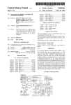
FIG. 3 is a functional block diagram of communication
board 40. As shown in FIG. 3, communication board 40
includes a communication device such as the aforemen
tioned fax/modem/voice chipset 41, and a 2/4 converter 42.
manipulate and view multimedia documents which contain
a variety of objects such as text objects, bitmap objects,
computer graphic objects, sound objects and motion video
voice communications and storing the digitized voice in a
computer ?le, and/or converting a digitized voice in com
puter ?les into analog form for play out over voice telephone
lines.
The communication board 40 further includes a data
access arrangement (DAA) which includes a line select
application programs such as a multimedia message marr
agement program, a word processing program, an image
are incorporated herein by reference. Such a fax/modem!
voice chipset provides a facsimile modem for automatic
facsimile transmission and reception, a data modem for
automatic data transmission and reception and a digital
The 2/4 converter 42 converts a four-Wire signal from the
30
objects, and to send and to receive such multimedia docu
ments via the communication board on one of the multiple
fax/modem/voice chipset 41 into a two-wire signal for
connection to ordinary voice telephone lines. The two-wire
signal from 2/4 converter 42 is fed to data access arrange
ment (DAA) 44. The data access arrangement, under control
telephone lines. The multimedia message management pro
gram may also be provided with telephone handset control
capabilities with which an operator, through manipulation
via control logic 45 from chipset 41 and computing equip
ment 10, switchably connects one of multiple telephone
lines, such as telephone lines 20 and 21, to the chipset via the
2/4 converter 42. Additionally, DAA 44 includes handset
and use of a computerized address list, may instruct the
computer to cause a selected telephone line to go off-hook,
a selected telephone number to be dialed, and indicate to the
40
switches for each telephone line for switchably connecting,
under control via control logic 45 from chipset 41 and
computing equipment 10, one of the telephone lines to
telephone handset 19.
Preferably, and as depicted in FIG. 3, the communication
board 40 is arranged on a single, multiple-layer, circuit
45
computer (RISC) interfaced to computer bus 31. Also inter
board provided with an edge connector 43 for connection to
computer bus 31, as well as suitable RJ-l4 connectors for
connection to handset 19 and telephone lines 20 and 21. The
single-board construction allows board 40 to be inserted into
faced to computer bus 31 is scanner interface 32 for inter
the housing of conventional PC-type computing equipment.
facing to scanner 18, display interface 34 for interfacing to
display 11, network interface 35 for interfacing to network
line 22, printer interface 36 for interfacing to printer 24,
keyboard interface 37 for interfacing to keyboard 15, and
pointing interface 38 for interfacing to pointing device 16.
Read only memory (ROM) 101 interfaces with computer
bus 31 so as to provide CPU 30 with specialized and
Of course, while a single-board construction is preferred, the
communication board 40 may, in fact, be comprised by
multiple interconnected circuit boards.
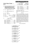
FIG. 4 is a schematic diagram illustrating the communi
cation board of FIG. 3. As shown in FIG. 4, the fax/modem!
operator that the called party has answered. Incoming calls
may also be handled by the computer, and a telephone usage
log may be maintained.
FIG. 2 is a detailed block diagram showing the internal
construction of computing equipment 10. As shown in FIG.
2, computing equipment 10 includes central processing unit
(CPU) 30 such as an 80386 or a reduced instruction set
invariant functions such as start-up programs or BIOS
programs. Main memory 110 which includes random access
memory (RAM) provides CPU 30 with memory storage
both for data and application programs, as required. In
particular, when executing stored program instruction
sequences such as multimedia message management pro
grams, CPU 30 nonnally loads those instruction sequences
from disk 14 (or other program storage media) to main
50
voice chipset 41 includes a modern controller 50 connected
55
via modem bus 51 to a modem data pump 52. Also con
nected to modern bus 51 are EPROM 54 and local RAM 55
which serve as memories for programming and processing
operations of the modem and which may have a capacity of
128K bytes each. An audio path in chipset 41 includes an
audio output interface portion 52a of the modem data pump
which is connectable to speaker 12, as well as an audio-in
switch 56 which permits connection to microphone 13 so as
to provide the modem data pump 52 with an audio input
memory 110 and executes those stored program instruction
interface under control of AND device 57.
sequences out of the main memory.
65
In operation, modem controller 50, via commands and
A communication board 40 which includes a data com~
data sent from computing equipment 10 on computer bus 31,
munication device is connected to computer bus 31 so as to
sets its state and the state of the modem data pump to one of