1
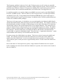
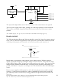
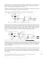
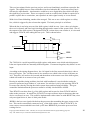
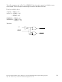
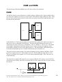
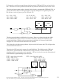
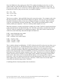
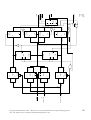
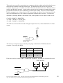
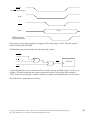
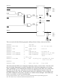
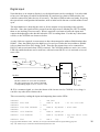
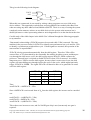
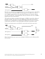
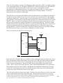
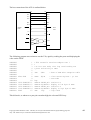
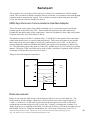
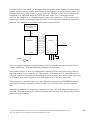
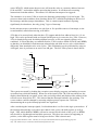
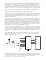
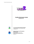
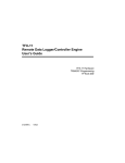
+5V
+5V
14
16
1
16MHz crystal
oscillator
8
2
7
0V
7
MR V
CEP
9
CC
CP
PE
74LS161 CET 10
Q
0 14
Q
1 13
Q
2
Q 12
GND
3 11
8
0V
8MHz out
4MHz out
2MHz out
1MHz out
The inputs taken high disable some of the extra features of the counter that are not required.
There was some ringing on the output, probably due to the high capacitance of the breadboard.
This could be rectified by using some form of RC network on the line if this causes a major
problem.
The 4 MHz output (‘161 pin 13) was connected to the 68000 clock input (pin 15).
Reset and Halt
The UM states that both /Reset and /Halt pins should be asserted for 100ms for a proper external
reset. There is a need for the system to be reset at power on as well as when a button is pressed.
As in the previous project, an RC network can be used to provide a pulse at power on.
5V
C
220nF
Vout
R
1M
0V
Initially there is no net charge on the capacitor, so no voltage across it. When the power is
applied, it gradually charges up, causing the voltage across it to increase. This causes the input
to the Schmitt Trigger to drop, giving a low-to-high transition on the output. This is precisely the
change required on the Reset and Halt lines. A switch across the capacitor will discharge it if
pressed, so it behaves as at power on, causing a reset. This also has the effect of debouncing the
switch.
However, these signals are bidirectional, so can be driven by the processor as well as external
circuitry. It is therefore not a good idea to connect a standard logic gate to them, because the
gate will always sink or source current, causing problems if the processor drives the line at the
same time.
Copyright Theo Markettos 1997. This may be used for educational and non-profit making purposes
only. The author may be reached at [email protected]
12