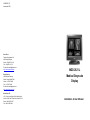
1
V5993223 / 00
November 2001
BarcoView
Theodoor Sevenslaan 106
8500 Kortrijk, Belgium
Phone: +32(0)56 23 32 44
Fax: +32(0)56 23 33 74
E-mail: [email protected]
http://www.barcoview.com
BarcoView Inc
3059 Premiere Parkway
Duluth, Georgia, 30097,USA
Phone: +1 678 475 8000
MGD 2621 L
Medical Greyscale
Display
Fax: +1 678 475 8100
E-mail: [email protected]
http://www.barcoview.com
BarcoView LTD
16F-1, Cheng Loong Plaza 33, Min Sheng Road
Section 1, Pan Chiao, Taipei Hsien, Taiwan, R.O.C.
Phone: +886 2 2957 8357
Fax: +886 2 2957 4080
Installation & User Manual
© 2001 BARCO nv. All rights reserved.
Trademark information
TrueGrey, MediCal, BarcoMed, and MeDis are registered trademarks
of BARCO NV.
Windows NT is a registered trademark of Microsoft Corporation.
MGD 2621L User's Guide 3
MGD 2621L User's Guide 4
SAFETY INSTRUCTIONS
• Read the safety and operating instructions
before operating the apparatus.
• Retain safety and operating instructions for
future reference.
• Adhere to all warnings on the apparatus
and in the operating instructions manual.
• Follow all instructions for operation and
use.
Regulations
• This apparatus conforms to: CE,
UL 2601-1, CAN/CSA-C22.2 No. 601.1-M90,
IEC 601-1, DHHS (TITLE 21 Subchapter J
Part 1020 )
• This apparatus is classified as Type B
without Applied Part.
Usage in Hazardous locations
• Class I equipment
• Equipment not suitable for use in the
presence of a flammable anaesthetic
mixture with air or with oxygen or nitrous
oxyde.
FCC notice
This equipment has been tested and found
to comply with the limits of a class B digital
device, pursuant to Part 15 of the FCC rules.
These limits are designed to provide
reasonable protection against harmful
interference when the equipment is operated
in a commercial environment. This equipment
generates, uses and can radiate radio
frequency energy and, if not installed and
used in accordance with the instruction
manual, may cause harmful interference to
radio communications. Operation of this
equipment in a residential area is likely to
cause harmful interference in which case the
user will be required to correct the interference
at his own expense.
Power connection
• Power cord: Utilise a UL-listed detachable
power cord, 3-wire, type SJ or equivalent, 18
AWG min., rated 300 V min., provided with a
hospital-grade type plug 5-15P configuration
for 120V application, or 6-15P for 240V
application.
• Warning: This apparatus must be earthed!
• Power requirements: connect the apparatus
to an AC voltage as indicated at its back.
Using a lower voltage, the apparatus will not
be able to operate. Using a higher voltage
may damage the apparatus.
If you are not sure of the type of power
supplied, consult the power company.
• Do not overload wall outlets and extension
cords as this may result in fire or electric
shock.
• Mains lead protection (U.S.: Power cord):
Supply cords should be routed so that they
are not likely to be walked upon or pinched by
items placed upon or against them, paying
particular attention to cords at plugs and
receptacles.
Water and moisture
• Never expose the apparatus to rain or
moisture.
• Never use the apparatus near water - e.g.
near a bathtub, washbasin, swimming pool,
kitchen sink, laundry tub or in a wet basement.
Ventilation
• Do not cover or block the ventilation openings
in the cover of the set. When installing the
apparatus in a cupboard or another closed
location, heed the necessary space between
the set and the sides of the cupboard.
Installation
• Place the apparatus on a flat, solid and
stable surface that can bear the weight of at
least 3 monitors. If you use an unstable cart
or stand, the set may fall, causing serious
injury to a child or adult, and serious damage
to the equipment.
More warnings in the Installation chapter.
MGD 2621L User's Guide 5
MGD 2621L User's Guide 6
CONTENTS
1. Introduction ..................................................................................................... 9
1.1 Overview .................................................................................................. 9
Resolution and bandwidths ....................................................................... 9
The memory system .................................................................................. 9
Image conformity and consistency ............................................................ 9
Calibration and adjustments .................................................................... 10
Remote control protocols ......................................................................... 10
Power saving system ............................................................................... 10
1.2 About the manuals ................................................................................. 10
2. Installation ..................................................................................................... 11
2.1 Precautions ............................................................................................ 11
2.2 The package contents ............................................................................ 11
2.3 Controls and connectors ........................................................................ 12
2.4 Signal connection ................................................................................... 13
a) Connection of video signals ................................................................ 13
b) Connection of data signals .................................................................. 13
c) Connection of optical sensor ............................................................... 15
d) Connection of power ............................................................................ 15
2.5 Positioning the display ........................................................................... 15
Important considerations .............................................................................. 16
3. Operation: User controls ............................................................................... 17
3.1 Switching on / off .................................................................................... 17
3.2 Contrast and brightness control ............................................................. 17
3.3 Viewing Status information ..................................................................... 20
3.4 Other adjustments .................................................................................. 21
4. Advanced settings and Adjustments (For service staff only) ........................ 22
4.1 Settings .................................................................................................. 22
4.2 Adjustments ............................................................................................ 24
a) How to make the adjustments ............................................................. 24
b) Description of the adjustments ............................................................ 24
Geometry ............................................................................................. 24
Focus ................................................................................................... 30
ALC ..................................................................................................... 30
Factory reset ....................................................................................... 30
c) How to save changes .......................................................................... 31
5. Maintenance ................................................................................................. 32
6. Troubleshooting ............................................................................................ 33
Appendix A: Background information ............................................................... 34
Luminance Uniformity Correction ............................................................ 34
Power saving system ............................................................................... 34
Appendix B: Technical specifications ............................................................... 36
MGD 2621L User's Guide 7
MGD 2621L User's Guide 8
1. INTRODUCTION
1.1 Overview
Resolution and bandwidths
The BARCO MGD 2621L is a high-resolution, greyscale display. Its
outstanding visual performance, combining a 2 MegaPixel resolution
with a high brightness, makes it ideal for diagnostic imaging and many
other medical and scientific applications.
The MGD 2621L is compatible with any AC power system worldwide
and automatically synchronizes to a wide range of sync frequencies.
Its high-speed video amplifier supports pixel clocks up to 250 MHz.
The memory system
The internal memory system can contain the adjustments for 16
different scanning formats, the so-called scanning modes. Eight of
them are adjusted and stored in the factory. Each scanning format is
characterized by its sync signals. The display’s internal micro
controller continuously samples the connected sync signals and
compares them to the scanning modes already stored in the memory.
If the connected signal has already been stored, the micro controller
adapts the image to the corresponding adjustment values in the
memory, and further adjustments are unnecessary.
Image conformity and consistency
Image conformity and consistency are the keywords. In our factory,
the MGD 2621L displays are perfectly adjusted and calibrated before
they are shipped to the customer. Internal circuits, like the TrueGrey®
and Automatic White Stability (AWS) systems, ensure display
consistency over time.
Conformity with the original image quality is guaranteed by the
automatic calibration, which can be done by means of an optical
sensor, connected to the Sensor connector on the display. The
sensor is not supplied with the display. Calibration is done from within
the BARCO MediCal® Pro software.
Introduction
9
Calibration and adjustments
The conformity calibration, as well as the complete adjustment of the
display, can be performed by means of the remote, user-friendly
MediCal® software package. MediCal, which runs under Microsoft
Windows NT, is especially developed to adjust and check BARCO’s
medical displays. MediCal can be ordered separately.
A lot of adjustments can also be done on the display itself, by means
of an extensive on-screen menu system, accessible by using the
control knob at the front.
Remote control protocols
The PC on which the remote control software runs, can communicate
with the MGD 2621L through 2 possible interfaces: RS-232 and USB.
For USB, the MGD 2621L provides a hub function. This means that
the user can connect peripheral USB devices, such as a keyboard or
mouse, to the display's USB down ports.
Power saving system
The MGD 2621L is equipped with a power saving system.
When left idle for a certain time, the computer, connected to the
display, will power down the display in several steps. The power
saving system can be switched on or off during the installation or
adjustment of the display.
This system requires a computer imaging board that supports power
saving management.
1.2 About the manuals
This guide is meant for people who want to install and use the MGD
2621L display, as well as people who need to install and adjust the
display. The chapter "Advanced Adjustments" is meant for trained
engineers only, because it describes actions and procedures that
require a technical skill to be performed properly.
The use of the software MediCal is described in the MediCal User’s
Manual.
Introduction
10
2. INSTALLATION
2.1 Precautions
•
Keep your original packaging. It is designed for this display and is
the ideal protection during transport.
•
Do not lift the display all by yourself to avoid injury.
•
Avoid reflections in the picture tube to reduce eye strain.
•
Place the display on a strong and stable table or desk if used as
desktop display.
•
Keep the display away from heat sources and provide enough
ventilation in case it is built in a rack or console.
•
Keep the display away from strong sources of magnetic fields.
•
Make sure the display and computer are both switched off before
connecting the signals.
2.2 The package contents
•
The MGD 2621L display
•
The accessory box (in which you found this manual)
Notes:
•
The MGD 2621L can be part of a complete MeDis® system,
consisting of the display itself, an imaging board and software. In
that case, the package contains a lot more items. The contents of
the package is then described in the manual of the complete
system.
•
The ambient light shield inside the accessory box should always
be used during conformity calibration with the X-Rite DTP92
optical sensor.
Installation
11
2.3 Controls and connectors
{1} Connector for optical sensor
(RS232 format).
BARCO
1
2
3 4 5
{2} Control knob, consisting of a
push button (at the front) and a
turning wheel (under the bezel).
The control knob is used for
switching the power on/off, and
selecting and performing
functions in the OSD (on-screen
display) menu.
{3} Power indicator
{4} USB downstream port
{5} Ambient Light Compensation
(ALC) sensor
{6} Power switch
{7} AC power input. Accepts a
voltage from 90 Vac to 264 Vac
(automatic).
{8} Input for video signal
{9} Input for Horizontal or
Composite sync signal
{10} Input for Vertical sync signal
{11} Output of serial data (RS232
format)
{12} Input for serial data (RS232
format)
{13} USB upstream port (1)
6
7
8 9 10
11 12 13 14
{14} USB downstream ports (3)
Installation
12
2.4 Signal connection
a) Connection of video signals
The connected equipment must comply to all relevant safety
demands.
Important: The use of low-quality video cables can distort the video
signal and influence diagnosis.
Connect the video output of the computer’s imaging board to the
video and sync inputs on the display’s rear panel. Use a proper
video cable. The video cable is not supplied with the display, unless
the display comes as part of a complete BARCO MeDis system, that
also contains an imaging board.
The inputs accept the following signals:
•
Video with separate horizontal and vertical sync.
•
- The video cable has 3 wires.
- Connect the video signal to the connector Video {8}.
- Connect the horizontal sync signal to the connector HS/CS {9}.
- Connect the vertical sync signal to the connector VS {10}.
Video with external composite sync.
•
- The video cable has 2 wires.
- Connect the video signal to the connector Video {8}.
- Connect the composite sync signal to the connector HS/CS {9}.
Video with internal composite sync (sync on video).
- The video cable has 1 wire.
- Connect the video (with sync) signal to the connector Video {8}.
Notes:
•
The video inputs cannot be connected in loop-through (daisychain).
•
The required video amplitude: 700 mV ± 3 dB.
•
The required sync. amplitude: 400 mV.
b) Connection of data signals
The display can be controlled remotely by a computer through the
serial data bus. A typical example of this, is the MediCal software that
controls the display. MediCal runs on a PC that is connected through
the serial data bus. This PC is not necessarily the same computer as
the one that produces the video signals.
Unlike the video signals, it is possible to daisy-chain the serial data
bus. This means you can control different displays from one PC.
Installation
13
On RS-232
1. Connect one end of the serial data
cable to one of the PC’s COM ports. If
the COM port has a 25-pin connector,
you will need to use a D25-to-D9
interface connector. The cable and
the interface connector are both
supplied with MediCal.
2. Connect the other end of the serial
data cable to the Remote In connector
{12} on the display’s rear panel.
3. For a daisy-chain application, connect the Remote Out connector
{11} of the first display to the Remote In connector {12} of the next
display.
On USB
1. Plug one end of the USB cable into a
USB port of the connected computer.
2. Plug the other end of the USB cable
into the USB upstream port {13} of the
display.
3. In case of loop-through connection,
plug one end of a second USB cable
into one of the USB downstream ports
{14} of the display. Plug the other end
into the upstream port {13} of the next
display.
4. The other USB downstream ports of
the monitor {14} can be used for the
connection of peripheral equipment,
like a mouse, keyboard, scanner, etc.
Note: Do not connect both RS-232 and USB to prevent conflicts.
Installation
14
c) Connection of optical sensor
To calibrate the display, connect the
optical sensor to the Sensor connector
{1} at the front.
BARCO
Notes:
•
The display supports the DTP 92 from
X-Rite as optical sensor.
•
The optical sensor is not supplied by
BARCO.
•
Always use the Ambient Light
Shield during calibration.
d) Connection of power
1. Power cord: Utilize a UL-listed detachable power cord, 3-wire, type
SJ or equivalent, 18 AWG min., rated 300 V min., provided with a
hospital-grade type plug 5-15P configuration for 120V application,
or 6-15P for 240V application.
2. Plug one end of the power cord into the rear of the
display (connector LINE {7}). Plug the other end into a
grounded AC power outlet. The display automatically
adapts to the voltage. The voltage range is:
90 - 264 VAC.
2.5 Positioning the display
The tilt and swivel base allows you to
adjust the height and viewing angle of the
display to obtain an optimal viewing
comfort.
Installation
15
Important considerations
•
The best environment for diagnostic imaging is one with
controlled and dimmed ambient light. The human eye's
sensitivity depends on the ambient light strength. It is most
sensitive to small contrast changes (or subtle image details)
at limited ambient light levels.
•
The best ambient light level, expressed in Lux, depends on
the application. An office illumination typically requires 500
Lux. A dimmed environment, like a softcopy room, requires
less than 100 Lux.
•
Using your display in a controlled and dimmed environment
also extends its lifetime, because the display can operate at
limited brightness and contrast. These levels correspond to
the calibrated position in most cases.
•
A controlled ambient light environment implies the ambient
light is as constant as possible. Cover windows to keep out
the daylight. Avoid switching the lights and viewing boxes on
and off. A consistent environment results in more image
consistency and less eye fatigue.
•
Avoid reflections in the picture tube. Provide indirect lighting.
Don't place the displays in front of or close to a light source
like a window or viewing box, although this may be very
tempting. As a rule of thumb, keep viewing boxes at least
one metre (3 feet) away from the displays.
Installation
16
3. OPERATION: USER CONTROLS
Important:
The best way to adjust and control the display is by using MediCal,
which displays the ideal test patterns for correct adjustment. However,
in case you do not dispose of MediCal, you can control and adjust the
display by means of the built-in On-Screen Display (OSD).
3.1 Switching on / off
Power on/off
Switch on the display by means of the power switch {6} at the rear.
To switch off the display so that the power is disconnected, toggle the
power switch {6} at the rear again.
Manual stand-by
To put the display in manual stand-by
mode, press the control knob {2} shortly.
As a result, the power indicator {3} turns
orange.
BARCO
Note: You cannot switch the display in
manual stand-by when the on-screen
display (OSD) is visible. In that case, first
exit the OSD, and then press the control
knob to switch to stand-by mode.
Control knob
Power indicator
To activate the display from stand-by mode, press the control knob
{2} again. As a result, the power indicator {3} turns green again.
3.2 Contrast and brightness control
Contrast and brightness can be controlled through the OSD menus.
To activate the OSD
Turn the turning wheel (under the bezel) from left to right or from right
to left. As a result, the OSD main menu appears.
Note: The wheel should turn over at least 30 degrees before the OSD
becomes visible.
Operation
17
MAIN MENU
-
Contrast
CAL
Brightness
CAL
Status information
Settings
Adjustments
Exit
The OSD main menu
The main menu indicates the current setting for contrast and
brightness.
This can be:
• CAL: The calibrated position. This is the preferred setting in a
controlled environment.
• ALC: For contrast only. This indicates the Ambient Light
Compensation (ALC) is on, and contrast is controlled
automatically, depending on the ambient light.
• <empty>
When the main menu does not specify a setting,
contrast or brightness is manually set to a
different value than the calibrated position.
To put contrast in calibrated position
1 Turn the wheel under the bezel to select Contrast in the OSD
main menu.
2 Press the control knob shortly. The contrast control menu appears.
3 In the contrast control menu, select Contrast CAL position and
press the control knob shortly.
Contrast
- Contrast CAL position
- Manual contrast adjustment
- Exit
Contrast control menu
To control contrast manually
1 Turn the wheel under the bezel to select Contrast in the OSD
main menu.
2 Press the control knob shortly. The contrast control menu appears.
3 In the contrast control menu, select Manual contrast adjustment
and press the control knob shortly. The contrast scroll bar appears.
4 Turn the wheel under the bezel until you have reached the desired
contrast.
5 Press the control knob shortly or wait a few seconds to return to
the contrast control menu.
Operation
18
6 In the contrast control menu, select Exit and press the control
knob shortly to return to the main menu. Alternatively, you can just
wait a few seconds, and the OSD returns to the previous menu
automatically.
Contrast
Contrast scroll bar. The short
stroke in the bar indicates the
calibrated position, the long stroke
indicates the current setting.
To put brightness in calibrated position
1 Turn the wheel under the bezel to select Brightness in the OSD
main menu.
2 Press the control knob shortly. The brightness control menu
appears.
3 In the brightness control menu, select Brightness CAL position
and press the control knob shortly.
Brightness
- Brightness CAL position
- Manual Brightness adjustment
- Exit
Brightness control menu
To control brightness manually
1 Turn the wheel under the bezel to select Brightness in the OSD
main menu.
2 Press the control knob shortly. The brightness control menu
appears.
3 In the brightness control menu, select Manual brightness
adjustment and press the control knob shortly. The brightness
scroll bar appears.
4 Turn the wheel under the bezel until you have reached the desired
brightness.
5 Press the control knob shortly or wait a few seconds to return to
the brightness control menu.
6 In the brightness control menu, select Exit and press the control
knob shortly to return to the main menu. Alternatively, you can just
wait a few seconds, and the OSD returns to the previous menu
automatically.
Operation
19
Brightness
Brightness scroll bar. The short
stroke in the bar indicates the
calibrated position, the long stroke
indicates the current setting.
3.3 Viewing Status information
You can view the status and actual settings of the display. You cannot
change them in the Status Menu. Changing the settings is reserved
for trained service staff only.
To view the status information
Turn the wheel under the bezel to select Status information in the
OSD main menu.
The Status information menu appears. The only control in the menu is
Exit.
STATUS INFORMATION
Display Name: MGD 2621L MKII
Serial Number:
5114147
Mode Name:
New mode
Mode H-frequency: 48.32 kHz
Mode V-frequency:
59.94 Hz
Software Version:
V 1.01
Run time:
50 hours
White level:
300 cd/m2
Activity timeout
30s
SH compensation
OFF
Actual H-frequency:72.02 kHz
Actual V-frequency: 75.00 Hz
- Exit
Status information menu
Explanation of the Status information menu items
Display Name:
This is the display type.
Serial Number:
This is the display's serial number.
Mode Name:
The currently selected scanning mode.
Operation
20
Mode H-frequency, Mode V-frequency:
These are the horizontal and vertical sync frequencies of the currently
selected scanning mode. These are the figures stored in the memory.
Software Version:
The internal software version.
Run time:
The total operating time since production, including burn-in time.
White level:
The display’s white level or light output after calibration, in calibrated
position.
Activity timeout :
This is the time, expressed in seconds, before the display interrupts
the data communication with the computer (e.g. during a computer
session with MediCal) if the computer does not respond anymore.
SH compensation (optional):
Indicates if Southern Hemisphere compensation is switched on or off.
Note: Southern Hemisphere compensation is an option. If the option
is not installed in the display, this line does not appear in the menu.
Actual H-frequency, Actual V-frequency:
These are the actual horizontal and vertical sync frequencies of the
connected video signal. They are measured constantly by the display.
3.4 Other adjustments
The main menu items Settings and Adjustments are reserved for
trained service staff and are therefore password - protected.
Operation
21
4.
ADVANCED SETTINGS AND
ADJUSTMENTS
(FOR SERVICE STAFF ONLY)
Important:
The functions and controls described in this chapter can have a
serious impact on the performance of the display. They should be
touched by trained service staff only!
4.1 Settings
SETTINGS INFORMATION
-
ALC
LUC
Orbiter
Power save
Display address
User controls disable
Exit
OFF
OFF
OFF
ON
1
OFF
The Settings menu
To change the settings
1 Turn the wheel under the display bezel from left to right or from
right to left to activate the On-Screen Display (OSD) main menu.
2 In the main menu, turn the wheel to select Settings.
3 Press and hold the control knob for a few seconds.
The Settings menu appears. It displays each setting and its current
status.
Note: If you press only shortly, the message "Service protected"
appears.
4 Turn the wheel to select the setting you want to change.
5 Press the control knob shortly to change the selected setting.
6 For Display address, you can change the setting by turning the
wheel. Return to the Settings menu by pressing the control knob.
For the other settings, the new status instantly appears in the
Settings menu.
Explanation of the Settings menu items
ALC:
ALC is short for Ambient Light Compensation. When this setting is on,
the contrast is controlled automatically, depending on the ambient
light, measured by the ALC sensor {5} in the bezel.
Advanced
22
LUC:
LUC is short for Luminance Uniformity Control. When switched on, the
internal waveform processor will modulate the gain of the video
amplifier so that the luminance is equal all over the screen (within a
tolerance of +/- 5%).
The LUC system can be calibrated in the Adjustments menu (see
further).
Orbiter:
The Orbiter is an internal circuit that, when switched on, will slightly
and slowly move the image to prevent pixel burn-in.
Power save:
This setting can switch the automatic power saving system (see
Introduction chapter) on or off.
Display address:
In multi-head systems (multiple displays controlled by one system),
each display must have a different address. With this setting you can
set the display address from 1 to 16.
User controls disable:
With this setting you can enable or disable the user controls.
When OFF, the user controls are not disabled, and the user can
activate and use the OSD menus.
When ON, the user controls are disabled. After quitting the OSD, the
user will no longer be able to activate the OSD.
To activate the OSD again when the user controls are disabled,
use the following "code":
1 Turn the wheel under the bezel 3 times from right to left.
2 Turn the wheel 3 times from left to right.
3 Turn the wheel 3 times from right to left.
Note: This should be done in quite a short time!
Saving the settings
The settings are automatically saved after changing them.
Advanced
23
4.2 Adjustments
a) How to make the adjustments
1 Turn the control knob at the rear from left to right or from right to
left to activate the On-Screen Display (OSD) main menu.
2 In the main menu, turn the control knob to select Adjustments.
3 Press the control knob for a few seconds.
The Adjustments menu appears.
Note: If you press only shortly, the message "Service protected"
appears.
4 Turn the control knob to select the category of adjustments you
want to make.
5 Press the control knob shortly to enter the selected category.
6 In the selected menu, select the adjustment you want to make and
press the control knob shortly to display the adjustment scroll bar.
7 Turn the control knob to perform the adjustment. After adjusting,
press the knob shortly to confirm the adjustment and return to the
menu, or press for a longer time to undo the adjustment and return
to the menu.
8 Return to the previous menu by pressing the control knob shortly
or selecting Exit when present.
b) Description of the adjustments
ADJUSTMENTS
-
Geometry
Focus
ALC
Luminance uniformity
Factory reset
Exit
Adjustments menu
Geometry
Rotation
Advanced
24
Auto geometry
Automatically adjusts geometry to almost 100% perfect. This
adjustment requires an image that covers the full screen, from left to
right and from top to bottom. E.g., the desktop pattern of a computer
is a good image.
Width
Horizontal position
Height
Vertical position
Blanking - Blanking left
Blanking - Blanking right
Advanced
25
Blanking - Blanking top
Interlacing - Pre correction
In most cases you do not need to change this adjustment.
You may need to increase this adjustment only when the connected
video and sync signal contains an abnormally big number of
equalization pulses before the vertical sync (more than 8 lines),
resulting in a phase error (geometry distortion) at the bottom of the
image.
Interlacing - Post correction
In most cases you do not need to change this adjustment.
You may need to increase this adjustment only when the connected
video and sync signal contains an abnormally big number of
equalization pulses after the vertical sync (more than 8 lines),
resulting in a phase error (geometry distortion) at the top of the image.
SH Compensation
If your display is equipped with the Southern Hemisphere option, the
on-screen display menu contains additional functions to adjust the
image geometry. If the option is not installed in the display, this menu
does not appear.
SH Compensation - SH Compensation ON/OFF
For proper geometry adjustment in the Southern Hemisphere, you
must switch SH Compensation ON. If not, the SH controls will not
function.
SH Compensation: SH Top
Advanced
26
SH Compensation: SH Bottom
SH Compensation: SH Position
With SH Compensation on, we advise to use the SH Position control
instead of the Horizontal Position control in the Geometry menu.
Advanced geometry - Horizontal skewing
Advanced geometry - Horizontal bowing
Advanced geometry - Horizontal trapezium
Advanced geometry - Horizontal parabola
Advanced
27
Advanced geometry - Corner top left
Advanced geometry - Corner top right
Advanced geometry - Corner bottom left
Advanced geometry - Corner bottom right
Advanced geometry - Linearity & S-correction Horizontal linearity
Advanced geometry - Linearity & S-correction Horizontal S-corr
Advanced geometry - Linearity & S-correction Vertical linearity
Advanced
28
Advanced geometry - Linearity & S-correction Vertical S-corr
Advanced geometry - Advanced bowing & skewing Horizontal bowing left
Advanced geometry - Advanced bowing & skewing Horizontal bowing right
Advanced geometry - Advanced bowing & skewing Horizontal skewing left
Advanced geometry - Advanced bowing & skewing Horizontal skewing right
Advanced
29
Focus
Static focus
Adjust Static focus to obtain an image as sharp as possible in the
center.
Focus zone
You can adjust the focus in 25 independent zones. Turn the wheel to
obtain an image as sharp as possible in the selected zone. Press the
control knob to switch to the next zone.
ALC
Minimum illuminance
Dim the light in the room. Adjust until you are satisfied with the
contrast of the picture.
Maximum illuminance
Create normal ambient light in the room. Adjust until you are satisfied
with the contrast of the picture.
Luminance uniformity
This menu allows you to calibrate the display, including the
Luminance Uniformity circuit.
Proceed as follows:
1 Connect the X-Rite DTP92 sensor and apply the black shield (see
chapter "Installation").
2 Follow the instructions on the screen.
Factory reset
This function allows you to undo all adjustments you have made since
the display left the factory.
Select Go ahead to restore the factory adjustments.
Select Exit to return to the previous menu without erasing the
adjustments.
Advanced
30
c) How to save changes
Proceed as follows:
1 After having made the adjustments, select Exit in each appearing
menu until the Save Changes? message appears.
2 Select Yes to save the changes.
Select No to exit the OSD menus without saving the changes.
What happens upon saving?
•
When the current scanning mode was already stored in the display
memory, the scanning mode is updated with the new adjustment
values.
•
When the scanning mode was not yet stored in the memory, the
display will create a new scanning mode in the memory.
However, when the memory was full, the monitor will display a list
of scanning modes in the memory and ask if you wish to overwrite
one of them. If you want to store the adjustments you have made,
you will have to overwrite one of the scanning modes in memory.
Advanced
31
5. MAINTENANCE
Picture tube
The glass panel of the picture tube is handled with a special coating.
Take care not to damage or scratch the coating.
Clean the picture tube with a soft woolen or cotton cloth.
The cloth should be moist, not wet!
Use a watery solution or a mild commercial glass cleaning solution.
Apply (e.g., spray) the solution on the cloth, not on the picture tube.
Cabinet
Clean the cabinet using a recognized cleaning product for medical
equipment. The cloth you use must be moist, not wet!
The cabinet has been tested for resistance to the following products:
Cidex, Betadine, Alcohol (Isopropyl and Ethyl), Ammonia-based
cleaners (Windex) and Aquasonic Gel.
Maintenance
32
6. TROUBLESHOOTING
There appears no image on the picture tube, the green LED on
the front is out
•
Check if the power cord is properly connected to the power outlet
and to the display.
•
Check if the power button is switched on.
There appears no image on the picture tube, the orange LED
is on
The display is switched in Stand-by, manually or by the automatic
Power saving system.
•
Press the control knob at the front shortly.
•
Try to switch on the display by pressing any key on the keyboard
of the computer that produces the video and sync. signals for the
display.
•
Check if both horizontal and vertical sync. signals are connected to
the display and to the computer.
On the picture tube appears the message "No Valid Sync
Signal"
•
Check if both horizontal and vertical sync. signals are connected to
the display and to the computer.
•
Check if the sync. signals are connected in the proper way (refer to
the chapter "Installation").
•
Check if both horizontal and vertical sync. frequencies match the
display specifications (refer to the chapter "Technical
specifications").
For other problems, please consult your technical service department.
Troubleshooting
33
APPENDIX A:
BACKGROUND INFORMATION
Luminance Uniformity Correction
A characteristic (or limitation) of every picture tube (CRT) is that the
luminance decreases towards the edge of the screen surface. The
decrease is normally 20 to 30 %.
This is caused by the shape of the picture tube. Inside the CRT, a socalled electron gun shoots an electron beam towards the front (the
glass panel). Because this panel is rather flat instead of having a
spheric shape, the electron beam has to 'travel' a longer distance in
the corners than in the center. So the intensity is higher in the center.
This phenomenon is even increased by the irregular distribution of the
phosphor and aluminium layer on the glass panel. These tend to be
thicker in the center.
BARCO has developed a special system, called Luminance
Uniformity Correction (LUC), that solves this problem. The LUC
system enhances the light output at the edges of the CRT, so that the
luminance there is the same as in the center.
The LUC system is calibrated in the factory. From time to time, it has
to be re-calibrated at the customer's site by means of the light sensor
you use for normal color calibration. The system can be calibrated
and switched on or off by a qualified technician.
Power saving system
The display is equipped with circuits that can handle power saving
management. When the system is switched on, it can power down the
display in several steps.
The system is controlled by the imaging board or the PC that delivers
the video signals. When you are working on the computer, the
imaging board delivers both sync signals, and the display is operating
normally. When you don't touch the computer keyboard for a certain
time, the imaging board only delivers vertical sync. This is sensed by
the display's micro controller, that blanks the image on the CRT. This
results in a drop of power consumption with about 25 %.
When you leave the computer idle for a longer period, the imaging
board now delivers horizontal sync only. As a result, the display's
micro controller switches off a number of internal circuits. The power
consumption has now dropped with about 42 %.
Background information
34
At last, the imaging board delivers no sync signals at all, and the
micro-controller switches off all but one power supplies in the display.
Only the micro-controller's own supply keeps on running, resulting in
a very low power consumption of 6 W.
If you start using the computer again, the imaging board switches on
both sync signals, and the micro-controller switches on the display.
The times after which the different steps of power management must
become active, is set in the PC's display properties.
Background information
35
APPENDIX B:
TECHNICAL SPECIFICATIONS
Picture tube:
Faceplate transmission: +/- 34%
Faceplate type: AR panel
Image representation: landscape
Phosphor: P45
Light output: (P45 phosphor)
Calibrated: 300 Cd/m2
Peak: 600 Cd/m2
Resolution:
Max. adress. pixels: 1600
Max. adress. lines: 1280
Scanning systems
Horizontal scanning:
Multi sync: -controller controlled
Minimum frequency: 30 kHz
Maximum frequency: 110 kHz
Minimum blanking : 2.2 s
Storable scan frequencies: 16
Prealigned scans: 8
Vertical scanning:
Minimum frequency: 50 Hz
Maximum frequency: 160 Hz
Minimum blanking: 300 s (after leading
edge)
Geometry
Nominal size (4/3 ratio): 396mm x 297mm
Nominal size (5/4 ratio): 370mm x 296mm
Inputs
Video
BNC connectors
Nominal level: 0.7 Vpp
Sync
BNC connectors
Nominal level: 1-4 Vpp
Communication inputs/outputs
RS232 9-pin sub D connector
Baudrate: 9600
USB: 1 up port, 4 down ports
Power supply:
Voltage: 90 - 264 V
Frequency: 45 - 65 Hz
Inrush current: 6 A
Environmental
Temperature range (°C):
Storage: -20/+65
Operation:
0/+45
Within specs:
15/+30
Altitude:
storage:
25 000 ft
operational:
10 000 ft
Humidity (relative):
95 % max., non condensing
Weight:
Unpacked
34.8 kg
Packed
40.4 kg
Dimensions packing (mm):
H x W x D: 740 * 620 * 580
Dimensions monitor (mm):
Height:
502 with tilt&swivel
438 without tilt&swivel
Width:
Depth:
500
527
Modifications reserved.
Technical specifications
36