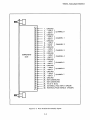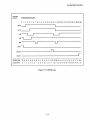
1
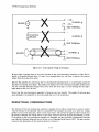
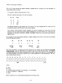
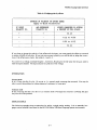
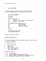
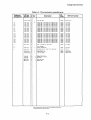
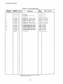
98640A Analog Input Interface
The A -to-O card receives the register address on address lines A 1 through A6 of the backplane. It
decodes these lines as follows:
A 1 through A 3 specify which channel to read.
A4 and AS specify what gain to use for the reading:
A5
A4
o
o
0
1
1
0
1
1
Gain
1
8
64
512
A6 indicates whether it is an analog read. If A6 is set to 1, it is an analog read; if it is set to 0, it is
an ordinary access to the ID, status, or pace timing register.
AO is ignored. Odd-numbered register addresses are used for accessing low bytes; since only full
words are read by analog reads, odd-numbered addresses are not used. (There is no AO line on the
backplane; its function is handled by BUDS- and BLDS- which are, as the minus signs indicate,
negative true.)
For example, if your read request specified a register address of 86, the A -to-D card would break
down that address as follows:
A6
A5
1
o
analog
read
A1
AO
1
011
o
gain
=8
channel
not
used
A4
A3
A2
=3
The value returned by an analog read is the voltage for the channel and gain specified tWQ..ana]og
r£.adurevicm.~. Thus, you must take n+2 readings to get the n values that you desire. For instance,
the example program below takes 3 readings to get 1 valid voltage value. (Refer to the paragraphs on
the "Analog Pipeline" at the end of Section 3 for a fuller explanation of this phenomenon.) The format for the returned value is:
15
14
13
12
11
10
9
8
7
6
5
4
3
2
1
o
+---+---+---+---+---+---+---+---+---+---+---+---+---+---+---+---+
I BIWIOI SIDIDIDIDIDlolDIDIDIDIDIDI
+---+---+---+---+---+---+---+---+---+---+---+---+---+---+---+---+
LSB
MSB
where.:
B = busy
W = wait
o =common mode overrange (0 =overrange; 1 = no overrange)
S =sign (0 = positive; 1 = negative)
D =data
(Refer to Section 3 for a more detailed explanation of the data word.)
4-2