1
≠
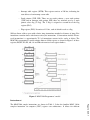
Data registers: There are four 16-bit registers (of which two registers R0 and R1 can be
used as 8-bit registers). For some instructions, registers R2 and R0 and registers R3 and
R1 can be combined for use as 32-bit data registers (R2R0, R3R1), respectively.
≠
Address registers: Two 16-bit registers A0 and A1. For some instructions, registers A1
and A0 can be combined for use as a 32-bit address register (A1A0).
≠
Base registers: Two 16-bit registers frame base (FB) and stack base (SB). These registers
consist of 16 bits each and are used in relative addressing.
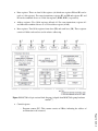
Figure 2 M16C/26A 48-pin version block diagram (adapted from M16C/26A group hardware
manual16)
≠
Control registers
/ Program counter (PC): This counter consists of 20bits, indicating the address of
an instruction to be executed.
Page 14.829.6