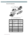
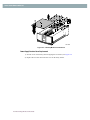
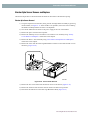
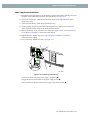
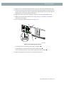
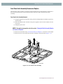
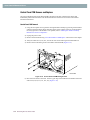
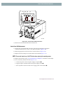
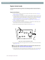
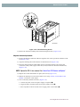
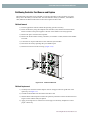
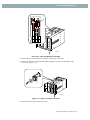
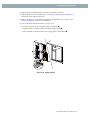
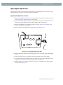
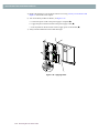
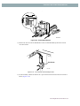
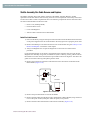
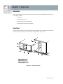
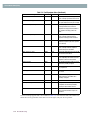
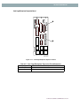
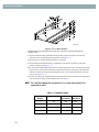
1
Neo Series
Neo Series™ Library
Service Manual
P/N 104241-xxx
Revision A February 2002
PROPRIETARY NOTICE
All information contained in or disclosed by this document is considered proprietary by Overland Data. By accepting this material the recipient
agrees that this material and the information contained therein are held in confidence and in trust and will not be used, reproduced in whole or in
part, nor its contents revealed to others, except to meet the purpose for which it was delivered. It is understood that no right is conveyed to reproduce or have reproduced any item herein disclosed without express permission from Overland Data.
Overland Data provides this manual as is, without warranty of any kind, either expressed or implied, including, but not limited to, the implied warranties of merchantability and fitness for a particular purpose. Overland Data may make improvements or changes in the product(s) or programs
described in this manual at any time. These changes will be incorporated in new editions of this publication.
Overland Data assumes no responsibility for the accuracy, completeness, sufficiency, or usefulness of this manual, nor for any problem that might
arise from the use of the information in this manual.
Worldwide
Headquarters
Sales
Technical Support
Overland Data, EMEA
Overland Data, Inc.
8975 Balboa Avenue
San Diego, CA 92123-1599
Toll Free: (800) 729-8725
Tel: (858) 571-5555
Fax: (858) 571-3664
Tel: (858) 571-5555
Fax: (858) 571-3664
E-mail: [email protected]
www.overlanddata.com
Tel: (858) 571-5555
Fax: (858) 571-3664
E-mail: [email protected]
Overland House, Ashville Way
Wokingham, Berkshire
RG41 2PL, England
Tel: +44 (0) 118-9898000
Fax: +44 (0) 118-9891897
www.overlanddata.com
Neo Series™ Service Manual
Preface
Purpose of This Manual
This manual provides step-by-step installation instructions, and information required for ongoing
use and maintenance for the Neo Series™ Libraries. This manual is written for the service provider
of this equipment. The following information is contained in this manual:
Chapter 1:
“Illustrated Parts Catalog” - Provides an illustrated parts and spares list.
Includes graphic representations of Neo Series Libraries.
Chapter 2:
“Servicing the Neo Series 2000” - Presents step-by-step procedures for removing and replacing Neo Series™ 2000 Library components.
Chapter3
“Servicing the Neo Series 4000” - Presents step-by-step procedures for removing and replacing Neo Series™ 4000 Library components.
Chapter 4:
“Operation” - Describes front panel operations for the Neo Series Library along
with inserting and removing tape cartridges, and tape requirements.
Chapter 5:
“Troubleshooting” - Describes the Power-On-Self-Test (POST) diagnostic test,
codes and correction procedures for Neo Series Libraries.
Chapter 6:
“Connectors, Switches and Indicators” - Lists and Describes the connectors,
switches, and LED indicators for the Neo Series Libraries
Appendix A:
“Specification” - Contains Neo Series Library specifications, and EMI compliance information.
Appendix B:
“Vertical Axis Alignment” - Presents step-by-step procedures for aligning the
vertical axis assembly. This procedure is required when components are
removed or replaced
Appendix C:
“Elevator Assembly Installation” - Presents procedures for Elevator installation including: rack preparation, minimum firmware, mechanical installation,
configuration and cabling.
Neo Series Libraries
Preface
ti
PREFACE
ii u Preface
Neo Series Libraries
Table of Contents
Purpose of This Manual ................................................................................. -i
Chapter 1 - Illustrated Parts Catalog
Introduction ................................................................................................. 1-1
Figure 1–1 Neo Series™ Library Modules ............................................. 1-1
Mechanical Parts Exploded View ............................................................... 1-2
Figure 1–2 Neo Series 2000 Mechanical Parts........................................ 1-2
Table 1-1 Neo Series 2000 Mechanical Parts List................................... 1-2
Figure 1–3 Neo Series 4000 Mechanical Parts........................................ 1-3
Table 1-2 Mechanical Spare Parts List .................................................... 1-3
Electrical Parts Exploded View .................................................................. 1-4
Figure 1–4 Neo Series™ 2000 Electrical Parts ....................................... 1-4
Table 1-3 Electrical Spare Parts List ....................................................... 1-4
Figure 1–5 Neo Series™ 4000 Electrical Parts ....................................... 1-5
Table 1-4 Electrical Spare Parts List ....................................................... 1-5
Chapter 2 - Servicing the Neo Series 2000
Introduction ................................................................................................. 2-1
Electrostatic Discharge Information ..................................................... 2-1
Preparation Procedures ......................................................................... 2-1
Weight Warning ................................................................................... 2-2
Emergency Magazine Removal .................................................................. 2-3
Figure 2–1 Manual Door Release ............................................................ 2-3
Figure 2–2 Magazine Removal................................................................ 2-3
Library Covers Remove and Replace ......................................................... 2-4
Tabletop Model Cover Removal .......................................................... 2-4
Figure 2–3 Tabletop Model Outer Skin Removal ................................... 2-4
Tabletop Model Cover Replacement .................................................... 2-4
Library Inside Covers ........................................................................... 2-4
Front Chassis Cover Removal ................................................................... 2-4
Front Chassis Cover Replacement ............................................................ 2-5
Fan Cover Assembly Removal ................................................................. 2-5
Figure 2–4 Cooling Fan Disconnect ........................................................ 2-5
Fan Cover Assembly Replacement ........................................................... 2-5
Power Supply Receiver Cover Removal ................................................... 2-5
Figure 2–5 Tabletop Model Cover Removal ........................................... 2-6
Power Supply Receiver Cover Replacement ............................................ 2-6
Parking the Shuttle Assembly Robotics for Service or Shipment .............. 2-7
If the library is operational ................................................................... 2-7
If the library is not operational ............................................................. 2-7
iii
TABLE OF CONTENTS (CONT’D)
Figure 2–6 Shuttle Brake Release ........................................................... 2-8
Figure 2–7 Shuttle Assembly in Parked Position .................................... 2-8
Front Panel Remove and Replace ............................................................... 2-9
Front Panel Removal ............................................................................ 2-9
Figure 2–8 Control Panel Board .............................................................. 2-9
Figure 2–9 Front Panel Removal........................................................... 2-10
Front Panel Replacement ................................................................... 2-10
Figure 2–10 Routing Front Panel Cables .............................................. 2-11
Figure 2–11 Powering up the Library.................................................... 2-12
GUI Assembly Remove and Replace ....................................................... 2-13
GUI Assembly Removal .................................................................... 2-13
Figure 2–12 GUI Assembly Remove and Replace................................ 2-13
GUI Assembly Replacement .............................................................. 2-13
Figure 2–13 Powering up the Library.................................................... 2-14
Front Panel LED Remove and Replace .................................................... 2-15
Front Panel LED Removal ................................................................. 2-15
Figure 2–14 Front Panel LED Remove ................................................. 2-15
Front Panel LED Replacement ........................................................... 2-15
Figure 2–15 Powering up the Library.................................................... 2-16
Front Panel Door Latch Remove and Replace .......................................... 2-17
Front Panel Door Latch Removal ....................................................... 2-17
Figure 2–16 Front Panel Solenoids Cable Tie....................................... 2-17
Figure 2–17 Front Panel Solenoid Remove and Replace ...................... 2-18
Front Panel Door Latch Replacement ................................................ 2-18
Figure 2–18 Powering up the Library.................................................... 2-19
Drive Shoe Assembly Remove and Replace ............................................ 2-20
Drive Shoe Assembly Removal ......................................................... 2-20
If the Library Will Remain Operational: ................................................. 2-20
If the library Will Not Be operational: .................................................... 2-20
Figure 2–19 Removing a Tape Drive .................................................... 2-21
Drive Shoe Assembly Replacement ................................................... 2-21
Figure 2–20 Installing a Tape Drive...................................................... 2-21
Figure 2–21 Powering up the Library.................................................... 2-22
Elevator Opto Sensor Remove and Replace ............................................. 2-23
Elevator Opto Sensor Removal .......................................................... 2-23
Figure 2–22 Access Plate Removal ....................................................... 2-23
Figure 2–23 Elevator Opto Sensor ........................................................ 2-24
Elevator Opto Sensor Replacement .................................................... 2-24
Figure 2–24 Powering up the Library.................................................... 2-25
Control Panel PCB Remove and Replace ................................................. 2-26
Control Panel PCB Removal .............................................................. 2-26
Figure 2–25 Control Panel PCB Remove and Replace ......................... 2-26
Control Panel PCB Replacement ....................................................... 2-26
Figure 2–26 Powering up the Library.................................................... 2-27
iv
TABLE OF CONTENTS (CONT’D)
Magazine Interlock Solenoid Assembly ................................................... 2-28
Magazine Interlock Solenoid Removal .............................................. 2-28
Figure 2–27 Mail Slot Solenoid Remove and Replace.......................... 2-28
Magazine Interlock Solenoid Replacement ........................................ 2-28
Figure 2–28 Powering up the Library.................................................... 2-29
Library Controller Card Remove and Replace ......................................... 2-30
Library Controller Removal. .............................................................. 2-30
Figure 2–29 Library Controller Card Removal ..................................... 2-30
Library Controller Replacement ......................................................... 2-30
Figure 2–30 Powering up the Library.................................................... 2-31
Fibre Channel Option Card Remove and Replace .................................... 2-32
FCO Card Removal ............................................................................ 2-32
Figure 2–31 FCO Card Removal........................................................... 2-32
FCO Card Replacement ..................................................................... 2-32
Figure 2–32 FCO Card Replacement .................................................... 2-33
Figure 2–33 Powering up the Library.................................................... 2-33
Power Supply Remove and Replace ......................................................... 2-34
Power Supply Removal ...................................................................... 2-34
Figure 2–34 Power Supply Remove and Replace ................................. 2-34
Power Supply Replacement ............................................................... 2-34
Figure 2–35 Powering up the Library.................................................... 2-35
Power Supply Receiver Remove and Replace .......................................... 2-36
Power Supply Receiver Removal ....................................................... 2-36
Figure 2–36 Power Supply Receiver Remove and Replace .................. 2-36
Power Supply Receiver Replacement ................................................ 2-37
Figure 2–37 Powering up the Library.................................................... 2-37
Card Cage Fan Remove and Replace ....................................................... 2-38
Card Cage Fan Removal .................................................................... 2-38
Figure 2–38 Card Cage Backplane Assembly ....................................... 2-38
Figure 2–39 Card Cage Backplane Connector Access Plate Removal.. 2-39
Figure 2–40 Card Cage Fan Removal ................................................... 2-39
Card Cage Fan Replacement .............................................................. 2-40
Figure 2–41 Powering up the Library.................................................... 2-40
Card Cage/Back Plane Remove and Replace ........................................... 2-41
Card Cage/Back Plane Removal ........................................................ 2-41
Figure 2–42 Card Cage Back Plane Assembly Removal ...................... 2-42
Card Cage/Back Plane Replacement .................................................. 2-42
Figure 2–43 Powering up the Library.................................................... 2-43
SCSI I/O Board and Plug Assembly ......................................................... 2-45
SCSI I/O Board and Plug Assembly Removal ................................... 2-45
Figure 2–44 SCSI I/O Board Removal.................................................. 2-46
Figure 2–45 SCSI I/O Board / Plug Assembly...................................... 2-46
SCSI I/O Board and Plug Assembly Replacement ............................ 2-46
Figure 2–46 Powering up the Library.................................................... 2-47
v
TABLE OF CONTENTS (CONT’D)
Drive Shield Remove and Replace ........................................................... 2-48
Drive Shield Removal ........................................................................ 2-48
Figure 2–47 Tape Drive Shield Removal .............................................. 2-48
Tape Drive Shield Replacement ......................................................... 2-48
Figure 2–48 Powering up the Library.................................................... 2-49
Drive Guides Remove and Replace .......................................................... 2-50
Drive Guides Removal ....................................................................... 2-50
Figure 2–49 Drive Guide Removal ....................................................... 2-50
Drive Guides Replacement ................................................................. 2-50
Figure 2–50 Powering up the Library.................................................... 2-51
Magazine Opto Sensors ............................................................................ 2-52
Magazine Opto Sensors Removal ...................................................... 2-52
Figure 2–51 Magazine Opto Sensor ...................................................... 2-52
Magazine Opto Sensors Replacement ................................................ 2-52
Figure 2–52 Powering up the Library.................................................... 2-53
Shuttle Assembly Track Sensor Remove and Replace ............................. 2-54
Shuttle Assembly Track Sensor Removal .......................................... 2-54
Figure 2–53 Shuttle Assembly Track Sensor Removal......................... 2-55
Shuttle Assembly Track Sensor Replacement ................................... 2-55
Figure 2–54 Powering up the Library.................................................... 2-56
Shuttle Assembly Robotics Remove and Replace .................................... 2-57
Shuttle Assembly Robotics Removal ................................................. 2-57
Figure 2–55 Shuttle Assembly Removal ............................................... 2-58
Shuttle Assembly Robotics Replacement .......................................... 2-58
Figure 2–56 Installing Flex Chain On Robot ........................................ 2-59
Figure 2–57 Powering up the Library.................................................... 2-60
Bar Code Reader Remove and Replace .................................................... 2-61
Bar Code Reader Removal ................................................................. 2-61
Figure 2–58 Bar Code Reader Removal ................................................ 2-61
Bar Code Reader Replacement .......................................................... 2-61
Figure 2–59 Powering up the Library.................................................... 2-62
Flex Cable/Chain Assembly ..................................................................... 2-63
Flex Cable/Chain Assembly Removal ............................................... 2-63
Figure 2–60 Shuttle Assembly In Parked Position ................................ 2-64
Figure 2–61 J6 and J3 Removal ............................................................ 2-64
Figure 2–62 Flex Chain Removal.......................................................... 2-65
Figure 2–63 Removing Flex Chain from Shuttle Assembly ................. 2-66
Flex Cable/Chain Assembly Replacement ......................................... 2-66
Figure 2–64 Installing Flex Chain on Robot ......................................... 2-67
Figure 2–65 Powering up the Library.................................................... 2-68
Cable Support Rod .................................................................................... 2-69
Cable Support Rod Removal .............................................................. 2-69
Figure 2–66 Cable Support Rod Removal............................................. 2-69
Cable Support Rod Replacement ....................................................... 2-69
vi
TABLE OF CONTENTS (CONT’D)
Figure 2–67 Powering up the Library.................................................... 2-70
Chapter 3 - Servicing the Neo Series 4000
Introduction ................................................................................................. 3-1
Electrostatic Discharge Information ..................................................... 3-1
Preparation Procedures ......................................................................... 3-1
Weight Warning ................................................................................... 3-2
Emergency Magazine Removal .................................................................. 3-3
Figure 3–1 Manual Door Release ............................................................ 3-3
Figure 3–2 Magazine Removal................................................................ 3-4
Library Covers Remove and Replace ......................................................... 3-5
Tabletop Cover Removal ..................................................................... 3-5
Figure 3–3 Tabletop Model Tabletop Cover Removal............................ 3-5
Tabletop Cover Replacement ............................................................... 3-5
Library Inside Covers ........................................................................... 3-5
Front Chassis Cover Removal ................................................................... 3-5
Front Chassis Cover Replacement ............................................................ 3-6
Fan Cover Assembly Removal ................................................................. 3-6
Figure 3–4 Cooling Fan Disconnect ........................................................ 3-6
Fan Cover Assembly Replacement ........................................................... 3-6
Power Supply Receiver Cover Removal ................................................... 3-7
Figure 3–5 Inside Covers Removal ......................................................... 3-7
Power Supply Receiver Cover Replacement ............................................ 3-7
Parking the Shuttle Assembly Robotics for Service or Shipment .............. 3-8
If the library is operational ................................................................... 3-8
If the library is not operational ............................................................. 3-8
Figure 3–6 Shuttle Brake Release............................................................ 3-9
Figure 3–7 Shuttle Assembly in Parked Position .................................... 3-9
Front Panel Remove and Replace ............................................................. 3-10
Front Panel Removal .......................................................................... 3-10
Figure 3–8 Front Panel Remove ............................................................ 3-11
Figure 3–9 Front Panel Removed .......................................................... 3-11
Front Panel Replacement ................................................................... 3-12
Figure 3–10 Applying Power ................................................................ 3-12
GUI Assembly Remove and Replace ....................................................... 3-13
GUI Assembly Removal .................................................................... 3-13
Figure 3–11 GUI Assembly Remove and Replace................................ 3-13
GUI Assembly Replacement .............................................................. 3-13
Figure 3–12 Applying Power ................................................................ 3-14
Front Panel LED Remove and Replace .................................................... 3-15
Front Panel LED Removal ................................................................. 3-15
Figure 3–13 LED Remove and Replace ................................................ 3-15
Front Panel LED Replacement ........................................................... 3-15
vii
TABLE OF CONTENTS (CONT’D)
Figure 3–14 Powering up the Library.................................................... 3-16
Front Panel Latch Assembly Remove and Replace .................................. 3-17
Front Panel Latch Assembly Removal ............................................... 3-17
Figure 3–15 Front Panel Latch Assembly ............................................. 3-17
Front Panel Latch Assembly Replacement ........................................ 3-18
Figure 3–16 Applying Power ................................................................ 3-18
Drive Shoe Assembly Remove and Replace ............................................ 3-19
Drive Shoe Assembly Removal ......................................................... 3-19
If the Library Will Remain Operational: ................................................. 3-19
If the library Will Not Be operational: .................................................... 3-19
Figure 3–17 Removing a Drive Shoe Assembly ................................... 3-20
Drive Shoe Assembly Replacement ................................................... 3-21
Figure 3–18 Installing a Tape Drive...................................................... 3-21
Control Panel PCB Remove and Replace ................................................. 3-22
Control Panel PCB Removal .............................................................. 3-22
Figure 3–19 Control Panel PCB Mounting Screws............................... 3-22
Figure 3–20 Control Panel PCB Connections ....................................... 3-23
Control Panel PCB Replacement ....................................................... 3-23
Figure 3–21 Applying Power ................................................................ 3-24
Mail Slot Interlock .................................................................................... 3-25
Mail Slot Interlock Removal .............................................................. 3-25
Figure 3–22 Control Panel PCB Cover Plate ........................................ 3-25
Figure 3–23 Magazine/Mail Slot Interlock Mounting Screws .............. 3-26
Mail Slot Interlock Replacement ........................................................ 3-26
Figure 3–24 Applying Power ................................................................ 3-27
Magazine Interlock Assembly .................................................................. 3-28
Magazine Interlock Removal ............................................................. 3-28
Figure 3–25 Control Panel PCB Cover Plate ........................................ 3-28
Figure 3–26 Interlock Mounting Screws ............................................... 3-29
Magazine Interlock Replacement ....................................................... 3-29
Figure 3–27 Applying Power ................................................................ 3-30
Library Controller Card Remove and Replace ......................................... 3-31
Library Controller Removal. .............................................................. 3-31
Figure 3–28 Library Controller Card Removal ..................................... 3-31
Library Controller Replacement ......................................................... 3-32
Figure 3–29 Applying Power ................................................................ 3-32
Fibre Channel Option Card Remove and Replace .................................... 3-33
FCO Card Removal ............................................................................ 3-33
Figure 3–30 FCO Card Removal........................................................... 3-33
FCO Card Replacement ..................................................................... 3-33
Figure 3–31 FCO Card Replacement .................................................... 3-34
Figure 3–32 Apply Power...................................................................... 3-34
Partitioning Controller Card Remove and Replace .................................. 3-35
FCO Card Removal ............................................................................ 3-35
viii
TABLE OF CONTENTS (CONT’D)
Figure 3–33 FCO Card Removal........................................................... 3-35
FCO Card Replacement ..................................................................... 3-35
Figure 3–34 FCO Card Replacement .................................................... 3-36
Figure 3–35 Apply Power...................................................................... 3-36
Power Supply Remove and Replace ......................................................... 3-37
Power Supply Removal ...................................................................... 3-37
Figure 3–36 Power Supply Remove and Replace ................................. 3-37
Power Supply Replacement ............................................................... 3-38
Power Supply Receiver Remove and Replace .......................................... 3-39
Power Supply Receiver Removal ....................................................... 3-39
Figure 3–37 Power Supply Reciever Remove and Replace .................. 3-40
Power Supply Receiver Replacement ................................................ 3-40
Figure 3–38 Applying Power ................................................................ 3-41
Card Cage Fan Remove and Replace ....................................................... 3-42
Card Cage Fans Removal ................................................................... 3-42
Upper Card Cage Fan Removal .............................................................. 3-42
Figure 3–39 Card Cage Backplane Connector Access Plate Removal.. 3-42
Figure 3–40 Card Cage Backplane Assembly ....................................... 3-43
Figure 3–41 Upper Card Cage Fan Removal ........................................ 3-43
Upper Card Cage Fan Replacement ........................................................ 3-44
Figure 3–42 Applying Power ................................................................ 3-44
Lower Card Cage Fan Removal .............................................................. 3-45
Figure 3–43 Card Cage Backplane Expansion PCB.............................. 3-45
Figure 3–44 Flex Cable Bracket Removal............................................. 3-46
Figure 3–45 Lower Card Cage Fan Removal ........................................ 3-46
Lower Card Cage Fan Replacement ....................................................... 3-46
Figure 3–46 Applying Power ................................................................ 3-47
Lower Card Cage Fan Bracket Assembly ................................................. 3-48
Fan Bracket Assembly Removal ........................................................ 3-48
Figure 3–47 Lower Card Cage Fan Bracket Removal........................... 3-48
Figure 3–48 Lower Card Cage Bracket Assembly ................................ 3-49
Fan Bracket Assembly Replacement .................................................. 3-49
Figure 3–49 Applying Power ................................................................ 3-50
Card Cage/Back Plane Remove and Replace ........................................... 3-51
Card Cage/Back Plane Removal ........................................................ 3-51
Figure 3–50 Card Cage Back Plane Assembly Removal ...................... 3-52
Card Cage/Back Plane Replacement .................................................. 3-53
Figure 3–51 Applying Power ................................................................ 3-54
Expansion Card Cage/Back Plane Remove and Replace ......................... 3-55
Expansion Card Cage/Back Plane Removal ...................................... 3-55
Figure 3–52 Expansion Card Cage/Backplane ...................................... 3-56
Expansion Card Cage/Back Plane Replacement ................................ 3-57
Figure 3–53 Applying Power ................................................................ 3-58
High Density SCSI I/O Boards and SCSI Connector Plate Assemblies ... 3-59
ix
TABLE OF CONTENTS (CONT’D)
SCSI I/O Board and the SCSI Connector Plate Assembly Removal . 3-59
Figure 3–54 SCSI I/O Board Removal.................................................. 3-60
Figure 3–55 SCSI I/O Board Removal.................................................. 3-60
SCSI I/O Board and the SCSI Connector Plate Assembly Replacement 3-61
Figure 3–56 Applying Power ................................................................ 3-61
Drive Divider Remove and Replace ......................................................... 3-62
Drive Divider Removal ...................................................................... 3-62
Figure 3–57 Wire Harness Cover Plate ................................................. 3-63
Figure 3–58 Drive Divider Removal ..................................................... 3-63
Drive Divider Replacement ................................................................ 3-64
Figure 3–59 Applying Power ................................................................ 3-64
Drive Guide Remove and Replace ............................................................ 3-65
Drive Guides Removal ....................................................................... 3-65
Figure 3–60 Drive Guide Removal ....................................................... 3-65
Drive Guides Replacement ................................................................. 3-66
Figure 3–61 Applying Power ................................................................ 3-66
Upper Magazine Opto Sensors ................................................................. 3-67
Upper Magazine Opto Sensors Removal ........................................... 3-67
Figure 3–62 Control Panel PCB Cover Plate ........................................ 3-67
Figure 3–63 Magazine Opto Sensors..................................................... 3-68
Upper Magazine Opto Sensors Replacement ..................................... 3-68
Figure 3–64 Applying Power ................................................................ 3-69
Lower Magazine Opto Sensors ................................................................. 3-70
Lower Magazine Opto Sensor Removal ............................................ 3-70
Figure 3–65 Control Panel PCB Cover Plate ........................................ 3-70
Figure 3–66 Magazine Opto Sensors..................................................... 3-71
Lower Magazine Opto Sensor Replacement ...................................... 3-71
Figure 3–67 Applying Power ................................................................ 3-72
Shuttle Assembly Track Sensor Remove and Replace ............................. 3-73
Shuttle Assembly Track Sensor Removal .......................................... 3-73
Figure 3–68 Track Sensor Removal ...................................................... 3-73
Shuttle Assembly Track Sensor Replacement ................................... 3-73
Figure 3–69 Applying Power ................................................................ 3-74
Elevator Opto Sensor Remove and Replace ............................................. 3-75
Elevator Opto Sensor Removal .......................................................... 3-75
Figure 3–70 Backplane Access Cover................................................... 3-75
Figure 3–71 Pass Thru Sensor Remove................................................. 3-76
Elevator Opto Sensor Replacement .................................................... 3-76
Figure 3–72 Powering up the Library.................................................... 3-77
Shuttle Assembly Robotics Remove and Replace .................................... 3-78
Removing the Robot Shuttle and Track Base .................................... 3-78
Figure 3–73 Flex Cable, carrier and clip removal ................................. 3-78
Figure 3–74 Rotate Track 90 Deg ......................................................... 3-79
Figure 3–75 Shuttle Brake Release ....................................................... 3-79
x
TABLE OF CONTENTS (CONT’D)
Figure 3–76 Removing Robotics Base .................................................. 3-80
Replacing the Robot Shuttle and Base ............................................... 3-80
Bar Code Reader Remove and Replace .................................................... 3-82
Bar Code Reader Removal ................................................................. 3-82
Figure 3–77 Bar Code Reader Removal ................................................ 3-82
Bar Code Reader Replacement .......................................................... 3-82
Figure 3–78 Applying Power ................................................................ 3-83
Front Vertical Axis Assembly Remove and Replace ............................... 3-84
Removing the Front Vertical Axis Assembly .................................... 3-84
Figure 3–79 Rotate Track 90 Deg ......................................................... 3-84
Figure 3–80 Shuttle Brake Release........................................................ 3-85
Figure 3–81 Front Vertical Axis Assembly Screws .............................. 3-85
Figure 3–82 Front Vertical Axis Motor Cable ...................................... 3-86
Figure 3–83 Front Vertical Axis Screws ............................................... 3-86
Replacing the Front Vertical Axis Assembly ..................................... 3-87
Figure 3–84 Shuttle Robot..................................................................... 3-87
Rear Vertical Axis Assembly Remove and Replace ................................ 3-88
Removing the Rear Vertical Axis Assembly ..................................... 3-88
Figure 3–85 Flex Cable, carrier and clip removal ................................. 3-88
Figure 3–86 Motor Cable / Mounting Screws ....................................... 3-89
Figure 3–87 Rear Vertical Axis Screws Removed ................................ 3-89
Replacing the Rear Vertical Axis Assembly ...................................... 3-90
Vertical Axis PCB Remove and Replace ................................................. 3-91
Controller Board Removal ................................................................. 3-91
Figure 3–88 Vertical Controller Board.................................................. 3-91
Replacing the Controller Board .......................................................... 3-92
Figure 3–89 Vertical Controller Board Removed ................................. 3-92
Figure 3–90 Applying Power ................................................................ 3-93
Robot Base Flex Cable Remove and Replace .......................................... 3-94
Robot Base Flex Cable Removal ....................................................... 3-94
Figure 3–91 Access Panel / Flex Cable Bracket.................................... 3-95
Figure 3–92 Removing Fan from the Standoffs .................................... 3-95
Figure 3–93 Track Mounting Screws .................................................... 3-96
Figure 3–94 Disconnecting Flex Cable at J1......................................... 3-96
Figure 3–95 Removing Flex Cable........................................................ 3-97
Figure 3–96 Disconnecting Flex Cable at J12....................................... 3-98
Robot Base Flex Cable Replacement ................................................. 3-98
Figure 3–97 Applying Power ................................................................ 3-99
Shuttle Assembly Flex Cable Remove and Replace ............................... 3-100
Robot Flex Cable Removal .............................................................. 3-100
Figure 3–98 Shuttle PCB ..................................................................... 3-100
Figure 3–99 Flex Cable, carrier and clip removal ............................... 3-101
Figure 3–100 Access Panel / Flex Cable Bracket................................ 3-101
Figure 3–101 Shuttle Flex Cable Connections .................................... 3-102
xi
TABLE OF CONTENTS (CONT’D)
Rotating Track Flex Cable Replacement ......................................... 3-102
Figure 3–102 Applying Power ............................................................ 3-103
Chapter 4 - Operation
Introduction ................................................................................................. 4-1
Front Panel .................................................................................................. 4-1
Figure 4–1 Library Front Panel ............................................................... 4-1
Magazine Doors ................................................................................... 4-2
Figure 4–2 Magazine Door Mechanical Release..................................... 4-2
Indicators .............................................................................................. 4-3
Figure 4–3 Library Indicators.................................................................. 4-3
Table 4-1 Indicators................................................................................. 4-3
Turning On The Libraries .................................................................... 4-3
Neo Series 2000 ........................................................................................ 4-3
Figure 4–4 Powering the Neo Series 2000 .............................................. 4-4
Neo Series 4000 ........................................................................................ 4-4
Figure 4–5 Powering The Neo Series 4000............................................. 4-4
Initialization Screen .............................................................................. 4-5
Figure 4–6 Initialization Screen .............................................................. 4-5
Library Default Screen ......................................................................... 4-5
Figure 4–7 Library Default Screen .......................................................... 4-5
Front Panel and Media Security Locks ................................................ 4-6
Passwords Screen ...................................................................................... 4-6
Figure 4–8 Library Password Levels....................................................... 4-6
Host System .............................................................................................. 4-7
Library Display Screens and Options ......................................................... 4-8
Technical Support Information Option ..................................................... 4-8
Figure 4–9 Technical Support Information Screen ................................. 4-8
Access Mail Slot Option (Left Magazine Only) ....................................... 4-9
Figure 4–10 Access Mail Slot Screen...................................................... 4-9
Access Magazine Option .......................................................................... 4-9
Figure 4–11 Access Magazine Screen................................................... 4-10
Move Media ............................................................................................ 4-10
Figure 4–12 Move Media Screen .......................................................... 4-10
Figure 4–13 Move Media Screen (Source)............................................ 4-11
Figure 4–14 Move Media Screen (Destination) .................................... 4-11
LCD Contrast Controls ........................................................................... 4-11
Power ...................................................................................................... 4-12
Figure 4–15 Power Down Initiation Screen .......................................... 4-12
Status ....................................................................................................... 4-13
Figure 4–16 Neo Series Status Screen................................................... 4-13
Online ...................................................................................................... 4-13
Menu Selections ........................................................................................ 4-14
xii
TABLE OF CONTENTS (CONT’D)
Figure 4–17 Menu Screen...................................................................... 4-14
View System Data .............................................................................. 4-15
Library Options ....................................................................................... 4-15
Figure 4–18 View Library Options Screen (Initial Screen)................... 4-15
Table 4-2 View Library Options............................................................ 4-15
SCSI Options ........................................................................................... 4-18
Figure 4–19 View SCSI Options Screen (Initial Screen) ...................... 4-18
Table 4-3 View SCSI Options ............................................................... 4-18
Network Options ..................................................................................... 4-20
Figure 4–20 View Network Options Screen.......................................... 4-20
Table 4-4 View Network Options.......................................................... 4-20
Library Info ............................................................................................. 4-20
Figure 4–21 View Library Info Screen.................................................. 4-21
Cartridge Map ......................................................................................... 4-21
Figure 4–22 Cartridge Map (page 1) ..................................................... 4-21
Edit Options ........................................................................................ 4-21
Library ..................................................................................................... 4-22
Figure 4–23 Edit Library Options Screen.............................................. 4-22
SCSI ........................................................................................................ 4-22
Figure 4–24 Edit SCSI Options Screen ................................................. 4-22
Network ................................................................................................... 4-23
Figure 4–25 Edit Network Options Screen............................................ 4-23
Passwords ................................................................................................ 4-23
Figure 4–26 Edit Passwords Options Screen......................................... 4-23
Utilities ............................................................................................... 4-24
Security Level ......................................................................................... 4-24
Figure 4–27 Security Level Screen........................................................ 4-24
Inserting and Removing Tape Cartridges ................................................. 4-25
Removing Magazines ......................................................................... 4-25
Figure 4–28 Removing Tape Cartridge Magazines............................... 4-25
Inserting Cartridges into a Magazine ................................................. 4-25
Figure 4–29 Tape Magazine with Tape Cartridges Installed................. 4-26
Using the Mail Slot (Left Magazines Only) ....................................... 4-26
Figure 4–30 Left Magazine Mail Slot ................................................... 4-27
Barcode Labels ................................................................................... 4-27
Figure 4–31 Barcode Label installation................................................. 4-27
Chapter 5 - Troubleshooting
Introduction ................................................................................................. 5-1
Platform Problems ...................................................................................... 5-1
Error Recovery ............................................................................................ 5-2
Figure 5–1 Troubleshooting Flow Chart ................................................. 5-2
Error Recovery Procedures ......................................................................... 5-3
xiii
TABLE OF CONTENTS (CONT’D)
Table 5-1 Error Recovery Procedures ..................................................... 5-3
Fault Symptom Codes (FSCs) .................................................................... 5-4
Table 5-2 Fault Symptom Codes ............................................................. 5-4
Chapter 6 - Connectors, Switches and Indicators
Introduction ................................................................................................. 6-1
Neo Series 2000 Connectors ....................................................................... 6-1
Library Controller Board .......................................................................... 6-1
Figure 6–1 Library Controller Board....................................................... 6-1
Table 6-1 Library Controller Board Connectors ..................................... 6-1
Control Panel Board .................................................................................. 6-2
Figure 6–2 Control Panel Board .............................................................. 6-2
Table 6-2 Control Panel Board Connectors............................................. 6-2
Card Cage/Backplane Assembly ............................................................... 6-3
Figure 6–3 Card Cage/Backplane Assembly........................................... 6-3
Table 6-3 Card Cage/Backplane Assembly Connectors.......................... 6-3
Shuttle Assembly Board ............................................................................ 6-4
Figure 6–4 Shuttle Assembly Board........................................................ 6-4
Table 6-4 Shuttle Assembly Board Connectors ...................................... 6-4
SCSI I/O Board ......................................................................................... 6-5
Figure 6–5 SCSI I/O Board (bottom side)............................................... 6-5
Table 6-5 SCSI I/O Board Connectors (bottom side).............................. 6-5
Figure 6–6 SCSI I/O Board (top side) ..................................................... 6-6
Table 6-6 SCSI I/O Board Connectors (top side).................................... 6-6
Hot Swap Library Board ........................................................................... 6-7
Figure 6–7 Hot Swap Library Board ....................................................... 6-7
Table 6-7 Hot Swap Library Board ......................................................... 6-7
Neo Series 4000 Connectors ................................................................ 6-8
Library Controller Board .......................................................................... 6-8
Figure 6–8 Library Controller Board....................................................... 6-8
Table 6-8 Library Controller Board Connectors ..................................... 6-8
Control Panel Board .................................................................................. 6-9
Figure 6–9 Control Panel Board .............................................................. 6-9
Table 6-9 Control Panel Board Connectors............................................. 6-9
Card Cage/Backplane Board ................................................................... 6-10
Figure 6–10 Card Cage/Backplane Board ............................................. 6-10
Table 6-10 Card Cage/Backplane Board Connectors............................ 6-10
Card Cage/Backplane Expansion Board ................................................. 6-11
Figure 6–11 Card Cage/Backplane Expansion Board ........................... 6-11
Table 6-11 Card Cage/Backplane Expansion Board Connectors .......... 6-11
Shuttle Assembly Board .......................................................................... 6-12
Figure 6–12 Shuttle Assembly Board.................................................... 6-12
Table 6-12 Shuttle Assembly Board Connectors .................................. 6-12
xiv
TABLE OF CONTENTS (CONT’D)
Mono Track Interface Board ................................................................... 6-13
Figure 6–13 Mono Track Interface Board ............................................. 6-13
Table 6-13 Mono Track Interface Board Connectors............................ 6-13
Vertical Axis Assembly Board ............................................................... 6-14
Figure 6–14 Vertical Axis Assembly Board.......................................... 6-14
Table 6-14 Vertical Axis Assembly Board Connectors ........................ 6-14
Upper and Lower SCSI I/O Boards ........................................................ 6-15
Figure 6–15 SCSI I/O Board (bottom side)........................................... 6-15
Table 6-15 SCSI I/O Board Connectors (bottom side).......................... 6-15
Figure 6–16 SCSI I/O Board (top side) ................................................. 6-16
Table 6-16 SCSI I/O Board Connectors (top side)................................ 6-16
Hot Plug Library Board ........................................................................... 6-17
Figure 6–17 Hot Plug Library Board..................................................... 6-17
Table 6-17 Hot Plug Library Board....................................................... 6-17
Switches .................................................................................................... 6-18
Library Controller Board .................................................................... 6-18
Figure 6–18 Library Controller Board Mode Switch ............................ 6-18
Power Supply ..................................................................................... 6-18
Figure 6–19 Power Supply (s) Power On/Off Switch ........................... 6-18
LED Indicators .......................................................................................... 6-19
Power Supply(s) Power-On LED Indicator ....................................... 6-19
Figure 6–20 Power Supply(s) Power-On LED Indicator ...................... 6-19
Library Status LED Indicator ............................................................. 6-19
Figure 6–21 Power Supply(s) Power-On LED Indicator ...................... 6-19
Appendix A - Specification
Hardware Specification ...............................................................................A-1
Table A–1 Hardware Specification .........................................................A-1
Environmental Specifications .....................................................................A-3
Safety ....................................................................................................A-3
Table A–2 Safety Specification...............................................................A-3
Electromagnetic Emissions ..................................................................A-4
Table A–3 Electromagnetic Emissions Specification..............................A-4
Electrostatic Discharge .........................................................................A-5
Table A–4 ElectroStatic Discharge Specification ...................................A-5
Temperature, Humidity and Altitude ...................................................A-5
Table A–5 Temperature Humidity and Altitude Specification................A-5
Shock ....................................................................................................A-5
Table A–6 Electromagnetic Emissions Specification..............................A-5
Vibration ...............................................................................................A-6
Table A–7 Vibration Specification..........................................................A-6
Primary Power ............................................................................................A-7
Voltage Limits ......................................................................................A-7
xv
TABLE OF CONTENTS (CONT’D)
Frequency Limits ..................................................................................A-7
Power Requirements ............................................................................A-7
Table A–8 Current ..................................................................................A-7
Sag / Surge Protection ..........................................................................A-8
Table A–9 Sag / Surge Protection ...........................................................A-8
Power Line Disturbance .......................................................................A-8
Table A–10 Power Line Disturbance ......................................................A-8
Cooling ........................................................................................................A-9
FCC Notice ...............................................................................................A-10
Japanese Voluntary Control Council for Interference (VCCI) ...............A-10
Translation ..............................................................................................A-10
Installation Considerations .......................................................................A-11
Rack Mounting ...................................................................................A-11
Input Supply .......................................................................................A-11
Grounding ...........................................................................................A-11
Appendix B - Vertical Axis Alignment
Alignment Procedure ..................................................................................B-1
Figure B–1 Applying Power....................................................................B-1
Figure B–2 Initialization Screen..............................................................B-2
Figure B–3 Menu Screen.........................................................................B-2
Figure B–4 Diagnostics Screen ...............................................................B-3
Figure B–5 Vertical Axis Calibration Screen..........................................B-3
Figure B–6 Mounting Screw Sequence ...................................................B-4
Figure B–7 Final Calibration Screen .......................................................B-5
Figure B–8 Initial Calibration Screen......................................................B-5
Figure B–9 Main Screen..........................................................................B-6
Appendix C - Elevator Assembly Installation
Introduction .................................................................................................C-1
Planning Your Installation ...................................................................C-2
Positioning Your Modules and the Elevator ........................................C-2
Verify Minimum Firmware Level ........................................................C-2
Figure C–1 Powering up the Library.......................................................C-3
Neo Series Router .......................................................................................C-4
Router Installation ................................................................................C-4
Figure C–2 Typical Router ......................................................................C-4
Figure C–3 Router Installed ....................................................................C-5
Installing the Elevator Assembly ................................................................C-6
Figure C–4 Drive Shoe/Blank Panel Removal ........................................C-7
Figure C–5 Cover Plate Removal ............................................................C-7
Figure C–6 Installing the Elevator Assembly..........................................C-9
Figure C–7 Installing a Tape Drive .......................................................C-10
xvi
TABLE OF CONTENTS (CONT’D)
Elevator Assembly Extension ...................................................................C-11
Mechanical Installation ......................................................................C-11
Elevator Assembly Required Tools ........................................................C-11
Orientation Of Parts During Assembly ...................................................C-12
Figure C–8 Factory Assembled Elevator Assembly..............................C-12
Preparing to Assemble the Elevator ...................................................C-12
Figure C–9 Elevator Bottom Plate.........................................................C-13
Figure C–10 Media Elevator Car...........................................................C-13
Figure C–11 Tensioner Ramp/Idler Pulley Zero Point..........................C-14
Figure C–12 Elevator Belt Block and Brackets.....................................C-14
Figure C–13 Tensioner Ramp/Idler Pulley............................................C-15
Figure C–14 Elevator Extension Alignment .........................................C-15
Figure C–15 Tie Bar Installation ...........................................................C-16
Table C-1 Timing Belt Lengths.............................................................C-16
Figure C–16 Timing Belt Installation Base Section ..............................C-17
Figure C–17 Timing Belt Installation....................................................C-17
Figure C–18 Timing Belt to Belt Block ................................................C-18
Figure C–19 Assembled Elevator and Extension ..................................C-19
Neo Series Module Configuration ............................................................C-20
Configuring Modules For Elevator Application ................................C-20
Figure C–20 Powering up the Library...................................................C-20
Configuring the Primary Master Module ................................................C-20
Figure C–21 Neo Main GUI Display.....................................................C-21
Figure C–22 Menu Screen.....................................................................C-21
Figure C–23 Module Configuration Select Screen................................C-22
Figure C–24 Module Configuration Screen ..........................................C-22
Figure C–25 Module Configuration Confirm........................................C-23
Figure C–26 Primary Master Screen .....................................................C-23
Configuring Slave Modules ....................................................................C-24
Figure C–27 Neo Main GUI Display.....................................................C-24
Figure C–28 Menu Screen.....................................................................C-24
Figure C–29 Module Configuration Select Screen................................C-25
Figure C–30 Module Configuration Screen ..........................................C-25
Figure C–31 Module Configuration Confirm........................................C-25
Figure C–32 Typical Configured Slaves ...............................................C-26
Cabling and Interface Connections ...........................................................C-27
Figure C–33 Typical Library Cabling ...................................................C-27
Figure C–34 Powering up the Library...................................................C-28
Verifying Firmware Level of the Slave Modules ...............................C-29
Fail-over Operation ...................................................................................C-30
Introduction ........................................................................................C-30
Fail-Over Terms ......................................................................................C-30
Cabling Considerations for Fail-Over Operation ....................................C-30
Fail-Over Initiation .............................................................................C-31
xvii
TABLE OF CONTENTS (CONT’D)
Local Fail-Over to Secondary Master Initiation .....................................C-31
Figure C–35 Secondary Master Screen .................................................C-31
Figure C–36 Secondary Master Menu Screen .......................................C-32
Figure C–37 Secondary Master Maintenance Screen............................C-32
Remote Fail-Over to Secondary Master Initiation ..................................C-33
Restoring Normal Operation ..............................................................C-34
Local Fail-over to Primary Master ..........................................................C-34
Figure C–38 Secondary Master Screen .................................................C-34
Figure C–39 Secondary Master Menu Screen .......................................C-35
Figure C–40 Secondary Master Maintenance Screen............................C-35
Remote Failover to Primary Master ........................................................C-35
xviii
List of Figures
Chapter 1 Illustrated Parts Catalog
Figure 1–1 Neo Series™ Library Modules........................................................... 1-1
Figure 1–2 Neo Series 2000 Mechanical Parts ..................................................... 1-2
Figure 1–3 Neo Series 4000 Mechanical Parts ..................................................... 1-3
Figure 1–4 Neo Series™ 2000 Electrical Parts .................................................... 1-4
Figure 1–5 Neo Series™ 4000 Electrical Parts .................................................... 1-5
Chapter 2 Servicing the Neo Series 2000
Figure 2–1 Manual Door Release ......................................................................... 2-3
Figure 2–2 Magazine Removal............................................................................. 2-3
Figure 2–3 Tabletop Model Outer Skin Removal ................................................ 2-4
Figure 2–4 Cooling Fan Disconnect ..................................................................... 2-5
Figure 2–5 Tabletop Model Cover Removal ........................................................ 2-6
Figure 2–6 Shuttle Brake Release......................................................................... 2-8
Figure 2–7 Shuttle Assembly in Parked Position ................................................. 2-8
Figure 2–8 Control Panel Board ........................................................................... 2-9
Figure 2–9 Front Panel Removal ........................................................................ 2-10
Figure 2–10 Routing Front Panel Cables............................................................ 2-11
Figure 2–11 Powering up the Library................................................................. 2-12
Figure 2–12 GUI Assembly Remove and Replace ............................................. 2-13
Figure 2–13 Powering up the Library................................................................. 2-14
Figure 2–14 Front Panel LED Remove .............................................................. 2-15
Figure 2–15 Powering up the Library................................................................. 2-16
Figure 2–16 Front Panel Solenoids Cable Tie .................................................... 2-17
Figure 2–17 Front Panel Solenoid Remove and Replace ................................... 2-18
Figure 2–18 Powering up the Library................................................................. 2-19
Figure 2–19 Removing a Tape Drive ................................................................. 2-21
Figure 2–20 Installing a Tape Drive ................................................................... 2-21
Figure 2–21 Powering up the Library................................................................. 2-22
Figure 2–22 Access Plate Removal .................................................................... 2-23
Figure 2–23 Elevator Opto Sensor...................................................................... 2-24
Figure 2–24 Powering up the Library................................................................. 2-25
Figure 2–25 Control Panel PCB Remove and Replace ...................................... 2-26
Figure 2–26 Powering up the Library................................................................. 2-27
Figure 2–27 Mail Slot Solenoid Remove and Replace....................................... 2-28
Figure 2–28 Powering up the Library................................................................. 2-29
Figure 2–29 Library Controller Card Removal .................................................. 2-30
Figure 2–30 Powering up the Library................................................................. 2-31
Figure 2–31 FCO Card Removal ........................................................................ 2-32
Figure 2–32 FCO Card Replacement.................................................................. 2-33
1
LIST OF FIGURES
Figure 2–33 Powering up the Library................................................................. 2-33
Figure 2–34 Power Supply Remove and Replace .............................................. 2-34
Figure 2–35 Powering up the Library................................................................. 2-35
Figure 2–36 Power Supply Receiver Remove and Replace ............................... 2-36
Figure 2–37 Powering up the Library................................................................. 2-37
Figure 2–38 Card Cage Backplane Assembly .................................................... 2-38
Figure 2–39 Card Cage Backplane Connector Access Plate Removal............... 2-39
Figure 2–40 Card Cage Fan Removal................................................................. 2-39
Figure 2–41 Powering up the Library................................................................. 2-40
Figure 2–42 Card Cage Back Plane Assembly Removal ................................... 2-42
Figure 2–43 Powering up the Library................................................................. 2-43
Figure 2–44 SCSI I/O Board Removal ............................................................... 2-46
Figure 2–45 SCSI I/O Board / Plug Assembly ................................................... 2-46
Figure 2–46 Powering up the Library................................................................. 2-47
Figure 2–47 Tape Drive Shield Removal ........................................................... 2-48
Figure 2–48 Powering up the Library................................................................. 2-49
Figure 2–49 Drive Guide Removal..................................................................... 2-50
Figure 2–50 Powering up the Library................................................................. 2-51
Figure 2–51 Magazine Opto Sensor ................................................................... 2-52
Figure 2–52 Powering up the Library................................................................. 2-53
Figure 2–53 Shuttle Assembly Track Sensor Removal ...................................... 2-55
Figure 2–54 Powering up the Library................................................................. 2-56
Figure 2–55 Shuttle Assembly Removal ............................................................ 2-58
Figure 2–56 Installing Flex Chain On Robot...................................................... 2-59
Figure 2–57 Powering up the Library................................................................. 2-60
Figure 2–58 Bar Code Reader Removal ............................................................. 2-61
Figure 2–59 Powering up the Library................................................................. 2-62
Figure 2–60 Shuttle Assembly In Parked Position ............................................. 2-64
Figure 2–61 J6 and J3 Removal.......................................................................... 2-64
Figure 2–62 Flex Chain Removal ....................................................................... 2-65
Figure 2–63 Removing Flex Chain from Shuttle Assembly............................... 2-66
Figure 2–64 Installing Flex Chain on Robot ...................................................... 2-67
Figure 2–65 Powering up the Library................................................................. 2-68
Figure 2–66 Cable Support Rod Removal .......................................................... 2-69
Figure 2–67 Powering up the Library................................................................. 2-70
Chapter 3 Servicing the Neo Series 4000
Figure 3–1 Manual Door Release ......................................................................... 3-3
Figure 3–2 Magazine Removal............................................................................. 3-4
Figure 3–3 Tabletop Model Tabletop Cover Removal ......................................... 3-5
Figure 3–4 Cooling Fan Disconnect ..................................................................... 3-6
Figure 3–5 Inside Covers Removal ...................................................................... 3-7
Figure 3–6 Shuttle Brake Release......................................................................... 3-9
2
LIST OF FIGURES
Figure 3–7 Shuttle Assembly in Parked Position ................................................. 3-9
Figure 3–8 Front Panel Remove ......................................................................... 3-11
Figure 3–9 Front Panel Removed ....................................................................... 3-11
Figure 3–10 Applying Power.............................................................................. 3-12
Figure 3–11 GUI Assembly Remove and Replace ............................................. 3-13
Figure 3–12 Applying Power.............................................................................. 3-14
Figure 3–13 LED Remove and Replace ............................................................. 3-15
Figure 3–14 Powering up the Library................................................................. 3-16
Figure 3–15 Front Panel Latch Assembly .......................................................... 3-17
Figure 3–16 Applying Power.............................................................................. 3-18
Figure 3–17 Removing a Drive Shoe Assembly ................................................ 3-20
Figure 3–18 Installing a Tape Drive ................................................................... 3-21
Figure 3–19 Control Panel PCB Mounting Screws ............................................ 3-22
Figure 3–20 Control Panel PCB Connections .................................................... 3-23
Figure 3–21 Applying Power.............................................................................. 3-24
Figure 3–22 Control Panel PCB Cover Plate...................................................... 3-25
Figure 3–23 Magazine/Mail Slot Interlock Mounting Screws ........................... 3-26
Figure 3–24 Applying Power.............................................................................. 3-27
Figure 3–25 Control Panel PCB Cover Plate...................................................... 3-28
Figure 3–26 Interlock Mounting Screws ............................................................ 3-29
Figure 3–27 Applying Power.............................................................................. 3-30
Figure 3–28 Library Controller Card Removal .................................................. 3-31
Figure 3–29 Applying Power.............................................................................. 3-32
Figure 3–30 FCO Card Removal ........................................................................ 3-33
Figure 3–31 FCO Card Replacement.................................................................. 3-34
Figure 3–32 Apply Power................................................................................... 3-34
Figure 3–33 FCO Card Removal ........................................................................ 3-35
Figure 3–34 FCO Card Replacement.................................................................. 3-36
Figure 3–35 Apply Power................................................................................... 3-36
Figure 3–36 Power Supply Remove and Replace .............................................. 3-37
Figure 3–37 Power Supply Reciever Remove and Replace ............................... 3-40
Figure 3–38 Applying Power.............................................................................. 3-41
Figure 3–39 Card Cage Backplane Connector Access Plate Removal............... 3-42
Figure 3–40 Card Cage Backplane Assembly .................................................... 3-43
Figure 3–41 Upper Card Cage Fan Removal...................................................... 3-43
Figure 3–42 Applying Power.............................................................................. 3-44
Figure 3–43 Card Cage Backplane Expansion PCB........................................... 3-45
Figure 3–44 Flex Cable Bracket Removal.......................................................... 3-46
Figure 3–45 Lower Card Cage Fan Removal ..................................................... 3-46
Figure 3–46 Applying Power.............................................................................. 3-47
Figure 3–47 Lower Card Cage Fan Bracket Removal........................................ 3-48
Figure 3–48 Lower Card Cage Bracket Assembly ............................................. 3-49
Figure 3–49 Applying Power.............................................................................. 3-50
Figure 3–50 Card Cage Back Plane Assembly Removal ................................... 3-52
3
LIST OF FIGURES
Figure 3–51 Applying Power.............................................................................. 3-54
Figure 3–52 Expansion Card Cage/Backplane ................................................... 3-56
Figure 3–53 Applying Power.............................................................................. 3-58
Figure 3–54 SCSI I/O Board Removal ............................................................... 3-60
Figure 3–55 SCSI I/O Board Removal ............................................................... 3-60
Figure 3–56 Applying Power.............................................................................. 3-61
Figure 3–57 Wire Harness Cover Plate .............................................................. 3-63
Figure 3–58 Drive Divider Removal .................................................................. 3-63
Figure 3–59 Applying Power.............................................................................. 3-64
Figure 3–60 Drive Guide Removal..................................................................... 3-65
Figure 3–61 Applying Power.............................................................................. 3-66
Figure 3–62 Control Panel PCB Cover Plate...................................................... 3-67
Figure 3–63 Magazine Opto Sensors.................................................................. 3-68
Figure 3–64 Applying Power.............................................................................. 3-69
Figure 3–65 Control Panel PCB Cover Plate...................................................... 3-70
Figure 3–66 Magazine Opto Sensors.................................................................. 3-71
Figure 3–67 Applying Power.............................................................................. 3-72
Figure 3–68 Track Sensor Removal ................................................................... 3-73
Figure 3–69 Applying Power.............................................................................. 3-74
Figure 3–70 Backplane Access Cover ................................................................ 3-75
Figure 3–71 Pass Thru Sensor Remove .............................................................. 3-76
Figure 3–72 Powering up the Library................................................................. 3-77
Figure 3–73 Flex Cable, carrier and clip removal .............................................. 3-78
Figure 3–74 Rotate Track 90 Deg....................................................................... 3-79
Figure 3–75 Shuttle Brake Release..................................................................... 3-79
Figure 3–76 Removing Robotics Base ............................................................... 3-80
Figure 3–77 Bar Code Reader Removal ............................................................. 3-82
Figure 3–78 Applying Power.............................................................................. 3-83
Figure 3–79 Rotate Track 90 Deg....................................................................... 3-84
Figure 3–80 Shuttle Brake Release..................................................................... 3-85
Figure 3–81 Front Vertical Axis Assembly Screws ........................................... 3-85
Figure 3–82 Front Vertical Axis Motor Cable.................................................... 3-86
Figure 3–83 Front Vertical Axis Screws ............................................................ 3-86
Figure 3–84 Shuttle Robot .................................................................................. 3-87
Figure 3–85 Flex Cable, carrier and clip removal .............................................. 3-88
Figure 3–86 Motor Cable / Mounting Screws .................................................... 3-89
Figure 3–87 Rear Vertical Axis Screws Removed ............................................. 3-89
Figure 3–88 Vertical Controller Board............................................................... 3-91
Figure 3–89 Vertical Controller Board Removed............................................... 3-92
Figure 3–90 Applying Power.............................................................................. 3-93
Figure 3–91 Access Panel / Flex Cable Bracket................................................. 3-95
Figure 3–92 Removing Fan from the Standoffs ................................................. 3-95
Figure 3–93 Track Mounting Screws ................................................................. 3-96
Figure 3–94 Disconnecting Flex Cable at J1 ...................................................... 3-96
4
LIST OF FIGURES
Figure 3–95 Removing Flex Cable..................................................................... 3-97
Figure 3–96 Disconnecting Flex Cable at J12 .................................................... 3-98
Figure 3–97 Applying Power.............................................................................. 3-99
Figure 3–98 Shuttle PCB .................................................................................. 3-100
Figure 3–99 Flex Cable, carrier and clip removal ............................................ 3-101
Figure 3–100 Access Panel / Flex Cable Bracket............................................. 3-101
Figure 3–101 Shuttle Flex Cable Connections ................................................. 3-102
Figure 3–102 Applying Power.......................................................................... 3-103
Figure 4–1 Library Front Panel ............................................................................ 4-1
Chapter 4 Operation
Figure 4–2 Magazine Door Mechanical Release .................................................. 4-2
Figure 4–3 Library Indicators ............................................................................... 4-3
Figure 4–4 Powering the Neo Series 2000 ........................................................... 4-4
Figure 4–5 Powering The Neo Series 4000 .......................................................... 4-4
Figure 4–6 Initialization Screen............................................................................ 4-5
Figure 4–7 Library Default Screen ....................................................................... 4-5
Figure 4–8 Library Password Levels .................................................................... 4-6
Figure 4–9 Technical Support Information Screen............................................... 4-8
Figure 4–10 Access Mail Slot Screen................................................................... 4-9
Figure 4–11 Access Magazine Screen ................................................................ 4-10
Figure 4–12 Move Media Screen........................................................................ 4-10
Figure 4–13 Move Media Screen (Source)......................................................... 4-11
Figure 4–14 Move Media Screen (Destination) ................................................. 4-11
Figure 4–15 Power Down Initiation Screen ....................................................... 4-12
Figure 4–16 Neo Series Status Screen ................................................................ 4-13
Figure 4–17 Menu Screen................................................................................... 4-14
Figure 4–18 View Library Options Screen (Initial Screen)................................ 4-15
Figure 4–19 View SCSI Options Screen (Initial Screen) ................................... 4-18
Figure 4–20 View Network Options Screen....................................................... 4-20
Figure 4–21 View Library Info Screen............................................................... 4-21
Figure 4–22 Cartridge Map (page 1) .................................................................. 4-21
Figure 4–23 Edit Library Options Screen........................................................... 4-22
Figure 4–24 Edit SCSI Options Screen .............................................................. 4-22
Figure 4–25 Edit Network Options Screen......................................................... 4-23
Figure 4–26 Edit Passwords Options Screen ...................................................... 4-23
Figure 4–27 Security Level Screen..................................................................... 4-24
Figure 4–28 Removing Tape Cartridge Magazines ............................................ 4-25
Figure 4–29 Tape Magazine with Tape Cartridges Installed.............................. 4-26
Figure 4–30 Left Magazine Mail Slot................................................................. 4-27
Figure 4–31 Barcode Label installation.............................................................. 4-27
Chapter 5 Troubleshooting
5
LIST OF FIGURES
Figure 5–1 Troubleshooting Flow Chart .............................................................. 5-2
Figure 6–1 Library Controller Board.................................................................... 6-1
Chapter 6 Connectors, Switches and Indicators
Figure 6–2 Control Panel Board ........................................................................... 6-2
Figure 6–3 Card Cage/Backplane Assembly ........................................................ 6-3
Figure 6–4 Shuttle Assembly Board..................................................................... 6-4
Figure 6–5 SCSI I/O Board (bottom side) ............................................................ 6-5
Figure 6–6 SCSI I/O Board (top side) .................................................................. 6-6
Figure 6–7 Hot Swap Library Board .................................................................... 6-7
Figure 6–8 Library Controller Board.................................................................... 6-8
Figure 6–9 Control Panel Board ........................................................................... 6-9
Figure 6–10 Card Cage/Backplane Board .......................................................... 6-10
Figure 6–11 Card Cage/Backplane Expansion Board ........................................ 6-11
Figure 6–12 Shuttle Assembly Board................................................................. 6-12
Figure 6–13 Mono Track Interface Board .......................................................... 6-13
Figure 6–14 Vertical Axis Assembly Board....................................................... 6-14
Figure 6–15 SCSI I/O Board (bottom side) ........................................................ 6-15
Figure 6–16 SCSI I/O Board (top side) .............................................................. 6-16
Figure 6–17 Hot Plug Library Board .................................................................. 6-17
Figure 6–18 Library Controller Board Mode Switch ......................................... 6-18
Figure 6–19 Power Supply (s) Power On/Off Switch ........................................ 6-18
Figure 6–20 Power Supply(s) Power-On LED Indicator.................................... 6-19
Figure 6–21 Power Supply(s) Power-On LED Indicator.................................... 6-19
Appendix A - Specification
Appendix B - Vertical Axis Alignment
Figure B–1 Applying Power .................................................................................B-1
Figure B–2 Initialization Screen ...........................................................................B-2
Figure B–3 Menu Screen ......................................................................................B-2
Figure B–4 Diagnostics Screen.............................................................................B-3
Figure B–5 Vertical Axis Calibration Screen .......................................................B-3
Figure B–6 Mounting Screw Sequence ................................................................B-4
Figure B–7 Final Calibration Screen ....................................................................B-5
Figure B–8 Initial Calibration Screen...................................................................B-5
Figure B–9 Main Screen .......................................................................................B-6
Appendix C - Elevator Assembly Installation
Figure C–1 Powering up the Library ....................................................................C-3
Figure C–2 Typical Router ...................................................................................C-4
Figure C–3 Router Installed..................................................................................C-5
Figure C–4 Drive Shoe/Blank Panel Removal .....................................................C-7
6
LIST OF FIGURES
Figure C–5 Cover Plate Removal .........................................................................C-7
Figure C–6 Installing the Elevator Assembly.......................................................C-9
Figure C–7 Installing a Tape Drive ....................................................................C-10
Figure C–8 Factory Assembled Elevator Assembly...........................................C-12
Figure C–9 Elevator Bottom Plate......................................................................C-13
Figure C–10 Media Elevator Car........................................................................C-13
Figure C–11 Tensioner Ramp/Idler Pulley Zero Point .......................................C-14
Figure C–12 Elevator Belt Block and Brackets..................................................C-14
Figure C–13 Tensioner Ramp/Idler Pulley.........................................................C-15
Figure C–14 Elevator Extension Alignment.......................................................C-15
Figure C–15 Tie Bar Installation ........................................................................C-16
Figure C–16 Timing Belt Installation Base Section ...........................................C-17
Figure C–17 Timing Belt Installation.................................................................C-17
Figure C–18 Timing Belt to Belt Block..............................................................C-18
Figure C–19 Assembled Elevator and Extension ...............................................C-19
Figure C–20 Powering up the Library ................................................................C-20
Figure C–21 Neo Main GUI Display..................................................................C-21
Figure C–22 Menu Screen ..................................................................................C-21
Figure C–23 Module Configuration Select Screen.............................................C-22
Figure C–24 Module Configuration Screen........................................................C-22
Figure C–25 Module Configuration Confirm .....................................................C-23
Figure C–26 Primary Master Screen ..................................................................C-23
Figure C–27 Neo Main GUI Display..................................................................C-24
Figure C–28 Menu Screen ..................................................................................C-24
Figure C–29 Module Configuration Select Screen.............................................C-25
Figure C–30 Module Configuration Screen........................................................C-25
Figure C–31 Module Configuration Confirm .....................................................C-25
Figure C–32 Typical Configured Slaves ............................................................C-26
Figure C–33 Typical Library Cabling ................................................................C-27
Figure C–34 Powering up the Library ................................................................C-28
Figure C–35 Secondary Master Screen ..............................................................C-31
Figure C–36 Secondary Master Menu Screen ....................................................C-32
Figure C–37 Secondary Master Maintenance Screen.........................................C-32
Figure C–38 Secondary Master Screen ..............................................................C-34
Figure C–39 Secondary Master Menu Screen ....................................................C-35
Figure C–40 Secondary Master Maintenance Screen.........................................C-35
7
LIST OF FIGURES
8
List of Tables
Chapter 1 Illustrated Parts Catalog
Table 1-1 Neo Series 2000 Mechanical Parts List............................................ 1-2
Table 1-2 Mechanical Spare Parts List ............................................................. 1-3
Table 1-3 Electrical Spare Parts List ................................................................ 1-4
Table 1-4 Electrical Spare Parts List ................................................................ 1-5
Chapter 4 Operation
Table 4-1 Indicators .......................................................................................... 4-3
Table 4-2 View Library Options..................................................................... 4-15
Table 4-3 View SCSI Options ........................................................................ 4-18
Table 4-4 View Network Options................................................................... 4-20
Chapter 5 Troubleshooting
Table 5-1 Error Recovery Procedures .............................................................. 5-3
Table 5-2 Fault Symptom Codes ...................................................................... 5-4
Chapter 6 Connectors, Switches and Indicators
Table 6-1 Library Controller Board Connectors............................................... 6-1
Table 6-2 Control Panel Board Connectors ...................................................... 6-2
Table 6-3 Card Cage/Backplane Assembly Connectors................................... 6-3
Table 6-4 Shuttle Assembly Board Connectors................................................ 6-4
Table 6-5 SCSI I/O Board Connectors (bottom side)....................................... 6-5
Table 6-6 SCSI I/O Board Connectors (top side) ............................................. 6-6
Table 6-7 Hot Swap Library Board .................................................................. 6-7
Table 6-8 Library Controller Board Connectors............................................... 6-8
Table 6-9 Control Panel Board Connectors ...................................................... 6-9
Table 6-10 Card Cage/Backplane Board Connectors ..................................... 6-10
Table 6-11 Card Cage/Backplane Expansion Board Connectors ................... 6-11
Table 6-12 Shuttle Assembly Board Connectors............................................ 6-12
Table 6-13 Mono Track Interface Board Connectors ..................................... 6-13
Table 6-14 Vertical Axis Assembly Board Connectors.................................. 6-14
Table 6-15 SCSI I/O Board Connectors (bottom side)................................... 6-15
Table 6-16 SCSI I/O Board Connectors (top side) ......................................... 6-16
Table 6-17 Hot Plug Library Board................................................................ 6-17
Appendix A - Specification
Table A–1 Hardware Specification.................................................................. A-1
Table A–2 Safety Specification ....................................................................... A-3
1
LIST OF TABLES (CONT’D)
Table A–3 Electromagnetic Emissions Specification...................................... A-4
Table A–4 ElectroStatic Discharge Specification ........................................... A-5
Table A–5 Temperature Humidity and Altitude Specification........................ A-5
Table A–6 Electromagnetic Emissions Specification...................................... A-5
Table A–7 Vibration Specification .................................................................. A-6
Table A–8 Current .......................................................................................... A-7
Table A–9 Sag / Surge Protection.................................................................... A-8
Table A–10 Power Line Disturbance............................................................... A-8
Appendix C - Elevator Assembly Installation
Table C-1 Timing Belt Lengths ......................................................................C-16
2
LIST OF TABLES (CONT’D)
3
LIST OF TABLES (CONT’D)
4
Chapter 1 Illustrated Parts Catalog
Introduction
This chapter provides the illustrated parts breakdown and a spare parts list for Neo Series Libraries.
See the table following each illustration for the names and referenced spare parts.
Figure 1–1. Neo Series™ Library Modules
Illustrated Parts Catalog
t 1-1
MECHANICAL PARTS EXPLODED VIEW
Mechanical Parts Exploded View
5
3
2
1
4
q
6
7
8
-
9
Neo-9070
Figure 1–2. Neo Series 2000 Mechanical Parts
Table 1-1 Neo Series 2000 Mechanical Parts List
Callout Number
1
u Illustrated Parts Catalog
Overland Part Number
BARCODE READER
108272-002
BARCODE READER LTO
106117-101
ROBOT
108286-002
ROBOT LTO
108286-003
3
FAN, BACKPLANE
108274-002
4
DRIVE, TAPE DLT
108275-003
DRIVE, TAPE SDLT
108275-004
DRIVE, TAPE LTO
108275-005
5
GUIDE, DRV
108278-002
6
POWER SUPPLY, Neo Series ™
2000
108285-002
7
BD, PS SUPPLY RCVR
108284-002
8
DSPLY, LCD TOUCH
108290-002
9
MAGAZINE, RIGHT
108281-004
-
MAGAZINE, LEFT
108281-003
q
BD, HOT-PLUG, LIBR
108280-002
2
1-2
Description
MECHANICAL PARTS EXPLODED VIEW
2
3
1
4
5
6
:
7
8
9
9
Neo-9142
:
Figure 1–3. Neo Series 4000 Mechanical Parts
Table 1-2 Mechanical Spare Parts List
Callout Number
Description
Overland Part Number
1
BARCODE READER
108272-002
2
ROBOT W/BARCODE READER
108306-002
3
FANS, BACKPLANE
108274-002
4
DRIVES, TAPE DLT W/FAN
108275-003
DRIVES, TAPE SDLT W/FAN
108275-004
5
GUIDE, DRV
108278-002
6
POWER SUPPLY, Neo Series ™
4000
108285-002
7
BD, PS SUPPLY RCVR
108310-002
8
DSPLY, LCD TOUCH
108290-002
9
MAGAZINE, RIGHT, UPPER, LOWER
108281-004
-
MAGAZINE, LEFT, UPPER, LOWER
108281-003
Illustrated Parts Catalog
t 1-3
ELECTRICAL PARTS EXPLODED VIEW
Electrical Parts Exploded View
4
3
5
2
1
6
7
8
9
10
11
12
10
11
Neo-9071
Figure 1–4. Neo Series™ 2000 Electrical Parts
Table 1-3 Electrical Spare Parts List
Callout Number
1-4
u Illustrated Parts Catalog
Description
Overland Part Number
1
BD, CONTROL PANEL
108291-002
2
CABLE,FLEX
108276-002
3
BD, BACKPLANE W/CAGE
108273-002
4
BD, CNTR, LIBR
108273-002
5
BD, HIGH DENSITY I/O SCSI
108288-002
6
CABLE, SCSI HD, 0.25 m
7
CABLE, SCSI HD, 0.5 m
8
TERMINATOR, HD, SCSI
9
BD, FRONT PANEL, LED
108291-002
-
INTERLOCK, FRONT PANEL
108292-002
q
CABLE, OPTO SENSOR SET
108283-002
w
INTERLOCK, MAIL SLOT
108293-002
ELECTRICAL PARTS EXPLODED VIEW
2
@
5
4
3
7
3
6
1
8
9
7
8
:
<
;
=
>
=
?
>
Neo-9143
Figure 1–5. Neo Series™ 4000 Electrical Parts
Table 1-4 Electrical Spare Parts List
Callout Number
Description
Overland Part Number
1
BD, CONTROL PANEL
2
CABLE,FLEX
108312-002
3
FRONT, VERTICAL GEAR ASSY
108309-002
REAR VERTICAL GEAR ASSY
108308-002
4
BD, BACKPLANE W/CAGE
108273-002
5
BD, CNTR, LIBR
108282-002
6
BD, EXPANSION, BACKPLANE
W/CAGE
108303-002
7
HIGH DENSITY I/O SCSI
108288-002
8
HOT-PLUG, LIBR
108280-002
9
CABLE, SCSI HD, 0.25 m
-
CABLE, SCSI HD, 0.5 m
q
TERMINATOR, HD, SCSI
w
FRONT PANEL, LED
108277-002
e
INTERLOCK, FRONT PANEL
108292-002
Illustrated Parts Catalog
t 1-5
ELECTRICAL PARTS EXPLODED VIEW
Table 1-4 Electrical Spare Parts List
Callout Number
1-6
u Illustrated Parts Catalog
Description
Overland Part Number
r
CABLE, OPTO SENSOR SET
108304-002
t
INTERLOCK, MAIL SLOT
108305-002
y
BD, VERTICAL AXIS CONTROLLER
108307-002
Chapter 2 Servicing the Neo Series 2000
Introduction
This chapter provides subassembly/module-level removal and replacement procedures for the Neo
Series™ 2000 Library Module. After completing all necessary removal and replacement
procedures, boot up the unit and run (if applicable) the appropriate Diagnostics software to verify
that all components operate properly.
To service the library, you may need the following:
•
Flat-blade screwdriver
•
Phillips screwdriver
• Wire cutters (for removing cable ties)
• .050 Hex Key
Electrostatic Discharge Information
A discharge of static electricity can damage static-sensitive devices or micro-circuitry. Proper
packaging and grounding techniques are necessary precautions to prevent damage. To prevent
electrostatic damage, observe the following precautions:
•
Transport products in static-safe containers such as conductive tubes, bags, or boxes.
•
Keep electrostatic-sensitive parts in their containers until they arrive at static-free
stations.
•
Cover the library with approved static-dissipating material. Provide a wrist strap
connected to the work surface and properly grounded tools and equipment.
•
Keep the work area free of non conductive materials, such as ordinary plastic assembly
aids and foam packing.
•
Make sure you are always properly grounded when touching a static-sensitive
component or assembly.
•
Avoid touching pins, leads, or circuitry.
•
Use conductive field service tools.
Preparation Procedures
System power in the library does not completely shut off using the Graphical User Interface (GUI)
touch screen. You must turn off library power using the On/Off switch located at the rear of the
power supply and then disconnect the AC power cord from the power supply to completely remove
all power from the library.
Servicing the Neo Series 2000
t 2-1
INTRODUCTION
CAUTION: To reduce the risk of electric shock or damage to the equipment, disconnect power from the
library by unplugging the power cord from either the electrical outlet or the power supply.
NOTE: It is necessary to be knowledgeable of electrostatic discharge information before
conducting the preparation procedures. For electrostatic discharge information, see
“Electrostatic Discharge Information” described earlier in this chapter.
Weight Warning
CAUTION: The library weighs 60 pounds (27.8 kilograms) when fully assembled.
To reduce the risk of personal injury or damage to equipment:
2-2
•
Observe local health and safety requirements and guidelines for manual material handling.
•
Obtain adequate assistance to lift and stabilize the library during installation or removal.
•
Remove all tape drives and power supply to reduce the overall weight of the library.
u Servicing the Neo Series 2000
EMERGENCY MAGAZINE REMOVAL
Emergency Magazine Removal
If a fault occurs that prevents removal of the magazines using the front panel Graphical User Interface
(GUI), the front panel access doors must be opened manually, see Figure 2–1.
1) Locate the Door Release Access holes in the grill area below the magazine doors.
2) Using a thin, stiff metal rod (such as a hex key, 0.050, or a straightened paper clip), push the
rod into the manual access door release until the door opens.
Left Magazine
Door Release
Right Magazine
Door Release
Neo-9300
Figure 2–1. Manual Door Release
3) The magazine may now be removed, see Figure 2–2.
1
2
Neo-9135a
1 Left Magazine
2 Right Magazine
Figure 2–2. Magazine Removal
Servicing the Neo Series 2000
t 2-3
LIBRARY COVERS REMOVE AND REPLACE
Library Covers Remove and Replace
Tabletop Model Cover Removal
1) Remove the four screws that secure the Outer Skin to the library chassis, see Figure 2–3.
2) Carefully slide the cover toward the rear of the library until it clears the front panel and then
lift it up and away from the library chassis.
Neo-9039
Figure 2–3. Tabletop Model Outer Skin Removal
Tabletop Model Cover Replacement
1) Place the tabletop cover to the rear of the library chassis, see Figure 2–3.
2) Carefully slide the cover toward the front of the library to the front panel.
3) Replace the four screws that secure the tabletop cover to the library chassis.
Library Inside Covers
The Library has three inside covers. The Front Chassis Cover can be removed to gain access to the
shuttle assembly, magazine solenoids, and control panel board. The Power Supply Receiver cover is used
to prevent internal access to the installed power supplies. The Fan Cover Assembly is used as a mounting
platform for the Fibre Channel Option cooling fan and to prevent internal access to the installed tape
drives and Card Cage/backplane assembly.
Front Chassis Cover Removal
1) Remove the two screws that secure the cover to the library chassis, see Figure 2–5.
2) Carefully slide the Front Chassis cover toward the front of the library to release the two rear
tabs and then lift it up and away from the library chassis.
2-4
u Servicing the Neo Series 2000
LIBRARY COVERS REMOVE AND REPLACE
Front Chassis Cover Replacement
1) Carefully slide the Front Chassis cover toward the back of the library and engage the two rear
tabs and seat the cover in the library chassis, see Figure 2–5.
2) Replace the two screws that secure the cover to the library chassis.
3) Replace the two screws that secure the cover to the library chassis.
Fan Cover Assembly Removal
1) Remove the 11 screws that secure the cover to the library chassis, (Figure 2–5).
2) Lift the inside edge of the Fan Cover Assembly and disconnect the cooling fan.
.
Figure 2–4. Cooling Fan Disconnect
3) Lift the cover up and away from the library chassis.
Fan Cover Assembly Replacement
1) Connect the power cable from the fan attached to the Fan Cover Assembly cover to the Y
connector coming from the card cage fan.
2) Lower the cover vertically towards the unit.
3) Ensure that the fan power cables do not bind between the cover and the top of the library
chassis.
4) Seat the cover on the library chassis aligning the screw holes, (Figure 2–5).
5) Replace the 11 screws that secure the cover to the library chassis.
Power Supply Receiver Cover Removal
1) Remove the 6 screws that secure the cover to the library chassis, see Figure 2–5.
2) Lift the cover up and away from the library chassis.
Servicing the Neo Series 2000
t 2-5
LIBRARY COVERS REMOVE AND REPLACE
Neo-9040
Figure 2–5. Tabletop Model Cover Removal
Power Supply Receiver Cover Replacement
1) Seat the cover on the library chassis aligning the screw holes, see Figure 2–5.
2) Replace the 6 screws that secure the cover to the library chassis.
2-6
u Servicing the Neo Series 2000
PARKING THE SHUTTLE ASSEMBLY ROBOTICS FOR SERVICE OR SHIPMENT
Parking the Shuttle Assembly Robotics for Service or Shipment
Many of the removal and replacement procedures require that the Shuttle Assembly be in the Parked
position to provide access to parts to be removed. When shipping the module it is important that the
Shuttle Assembly be in the Parked position to prevent damage while being handled in transit. Park the
Shuttle Assembly Robot as follows.
If the library is operational
1) Turn off the power using the Graphical User Interface (GUI). The controlled power off routine
will move the Shuttle Assembly to the Parked position, see Figure 2–6 and Figure 2–7.
2) Turn off the Master Power Switch on the power supply at the rear of the module.
3) Remove the power cord from the receptacle.
4) It is now safe to proceed with the service or shipment. Proceed to Step (5) below.
If the library is not operational
1) Turn off the Master Power Switch on the power supply at the rear of the module. Unplug the
power cord.
2) Look through the view port at the front of the module and determine if the Shuttle Assembly
is in the Parked position.
3) If it is in the Parked position or anywhere on the stationary track section, then it is safe to
proceed with the service or shipment.
4) If the Shuttle Assembly is on the rotating track section, then it must be moved to the stationary
section for shipment. Proceed to Step (5).
NOTE: It may not need to be moved for service.
5) Remove the tabletop cover and front main cover of the module using the “Library Covers
Remove and Replace” instructions in this chapter.
6) Turn the rotating track section counter-clockwise to align the track sections.
7) Release the brake by using the brake release lever and push the Shuttle Assembly at the base
near the track until it is completely on the stationary track section, see Figure 2–6 and
Figure 2–7.
Servicing the Neo Series 2000
t 2-7
PARKING THE SHUTTLE ASSEMBLY ROBOTICS FOR SERVICE OR SHIPMENT
.
Neo-9038
Figure 2–6. Shuttle Brake Release
8) Release the brake release lever and verify that it is locked.
9) Replace the tabletop cover and front main cover using “Library Covers Remove and Replace”
instructions in this chapter if the library is to be shipped.
10) It is now safe to proceed with the service or shipment.
.
Stationary Track
Section
Rotating Track
Section
Neo-9037
Figure 2–7. Shuttle Assembly in Parked Position
2-8
u Servicing the Neo Series 2000
FRONT PANEL REMOVE AND REPLACE
Front Panel Remove and Replace
The Front Panel assembly mounts on the front of the main chassis of the library. It includes a replaceable
Graphical User Interface (GUI), a replaceable Front Panel LED, and replaceable Front Panel Solenoids
for the left and right magazine door lock mechanisms. The Front Panel must be removed to replace the
GUI, Front Panel LED, and the Front Panel Solenoids.
Front Panel Removal
1) Using the GUI, open the magazine doors and remove the two magazines. If the module is not
operable, refer to “Emergency Magazine Removal” procedures.
2) Using the GUI, park the cartridge Shuttle Assembly by powering off the module and then
switch the Master Power Switch at the rear of the module to the off (0) position. If the module
is not operable, refer to “Parking the Shuttle Assembly Robotics for Service or Shipment”.
3) Remove the power cord from the receptacle.
4) Remove the tabletop cover and front main cover using “Library Covers Remove and Replace”
instructions in this chapter.
5) Locate the Control Panel Printed Circuit Board (PCB) assembly in the bottom of the chassis
behind the front panel, see Figure 2–8. Disconnect the cables at J14, J16, J13 and J3.
Disconnect the zero insertion force cable at J15 by sliding-up the body of the connector to
release the flex cable. Remove the flex cable from the connector.
.
J15
J16
J14
J13
J3
Neo-9041
Figure 2–8. Control Panel Board
6) Open the magazine doors using the door release in the front of the panel. Refer to the section
“Emergency Magazine Removal” if necessary.
Servicing the Neo Series 2000
t 2-9
FRONT PANEL REMOVE AND REPLACE
7) While holding the Front Panel against the chassis, remove the 2 screws that hold the Front
Panel to the chassis, see Figure 2–9.
8) Remove the 2 screws behind the chassis ears located at the top corners.
9) Carefully pull the top of the Front Panel away from the chassis about one inch and then lift up
on the Front Panel so that the four tabs that hold the panel at the bottom clear the chassis.
10) Guide the cables out through the chassis opening while removing the Front Panel, see
Figure 2–9.
.4
Molded Tab
Opening (4)
Molded Tab (4)
Neo-9042
Figure 2–9. Front Panel Removal
Front Panel Replacement
1) Position the Front Panel near the chassis and guide the cables through the chassis opening.
NOTE: The cables are to be routed through the lower-right part of the L-shaped opening that is
close to the bottom of the chassis. See Figure 2–10. Be especially careful that the flex cable
stays on top of the 15 pin flat cable and does not get twisted or folded as it goes through the
chassis.
2-10
u Servicing the Neo Series 2000
FRONT PANEL REMOVE AND REPLACE
.
Neo-9043
Figure 2–10. Routing Front Panel Cables
2) With the Front Panel pivoted at a slight angle, position the four tabs at the bottom of the Front
Panel in the chassis openings and then slip the tabs over the chassis.
3) Pivot the top of the Front Panel against the chassis.
4) Replace the four screws that hold the Front Panel to the chassis.
5) Replace the cables to the Control Panel PCB at connectors at J14, J16, J13 and J3. Carefully
connect the zero insertion force cable at J15.
6) Replace the tabletop cover and front main cover using “Library Covers Remove and Replace”
instructions in this chapter.
Servicing the Neo Series 2000
t 2-11
FRONT PANEL REMOVE AND REPLACE
7) Turn on the library module as follows, see Figure 2–11.
2
1
3
Neo-0004
Figure 2–11. Powering up the Library
a.Connect the power cord to the power supply’s receptacle (1).
b.Toggle the power switch located on the power supply to ON (2).
c.Press anywhere on the GUI touch screen to apply power to the module (3).
2-12
u Servicing the Neo Series 2000
GUI ASSEMBLY REMOVE AND REPLACE
GUI Assembly Remove and Replace
The Graphical User Interface (GUI) assembly is mounted on the inside of the Front Panel. The Front
Panel must be removed to replace the GUI Assembly.
GUI Assembly Removal
1) Using the GUI, park the cartridge Shuttle Assembly by powering off the module and then
switch the Master Power Switch on the power supply at the rear of the module to the off (0)
position. If the module is not operable, refer to “Parking the Shuttle Assembly Robotics for
Service or Shipment”. Remove the power cord from the receptacle.
2) Remove the Front Panel as described in “Front Panel Remove and Replace”.
3) Place the Front Panel face down on the work surface. Use some cushioning material to protect
the finish of the Front Panel.
4) Remove the four screws with insulating washers that hold the GUI Assembly to the Front
Panel, see Figure 2–12.
.
Neo-9044
Figure 2–12. GUI Assembly Remove and Replace
5) Lift the GUI Assembly from the Front Panel.
GUI Assembly Replacement
1) Place the GUI Assembly on the mounting posts with the ribbon cable and flex cable to the
right, see Figure 2–12.
2) Replace the four mounting screws and insulating washers with the insulating washers between
the mounting screw washer and the PCB.
3) Replace the Front Panel Assembly using the instructions “Front Panel Remove and Replace”.
4) Turn on the library module as follows, see Figure 2–13.
Servicing the Neo Series 2000
t 2-13
GUI ASSEMBLY REMOVE AND REPLACE
2
1
3
Neo-0004
Figure 2–13. Powering up the Library
a.Connect the power cord to the power supply’s receptacle (1).
b.Toggle the power switch located on the power supply to ON (2).
c.Press anywhere on the GUI touch screen to apply power to the module (3).
2-14
u Servicing the Neo Series 2000
FRONT PANEL LED REMOVE AND REPLACE
Front Panel LED Remove and Replace
The Front Panel LED is mounted inside the Front Panel. The Front panel GUI Assembly must be
removed to replace the Front Panel LED.
Front Panel LED Removal
1) Using the GUI, park the cartridge Shuttle Assembly by powering off the module and then
switch the Master Power Switch on the power supply at the rear of the module to the off (0)
position. If the module is not operable, refer to “Parking the Shuttle Assembly Robotics for
Service or Shipment”.
2) Turn off the Master Power Switch on the power supply at the rear of the module.
3) Remove the power cord from the receptacle.
4) Remove the Front Panel as described in “Front Panel Remove and Replace”.
5) Remove the GUI Assembly as described in “GUI Assembly Remove and Replace”.
6) Note the location of the cable tie that is near the left-handed door solenoid that ties the two
solenoid cables and the front panel LED to the Front Panel.
7) Remove the two screws that mount the LED to the Front Panel, (Figure 2–14).
Neo-9044c
Figure 2–14. Front Panel LED Remove
Front Panel LED Replacement
1) Position the Front Panel LED on the mounting posts with the cable to the right.
2) Replace the two mounting screws, (Figure 2–14).
3) Replace the GUI Assembly as described in “GUI Assembly Remove and Replace”.
4) Replace the Front Panel as described in “Front Panel Remove and Replace”
Servicing the Neo Series 2000
t 2-15
FRONT PANEL LED REMOVE AND REPLACE
5) Turn on the library module, see Figure 2–15.
2
1
3
Neo-0004
Figure 2–15. Powering up the Library
a.Connect the power cord to the power supply’s receptacle (1).
b.Toggle the power switch located on the power supply to ON (2).
c.Press anywhere on the GUI touch screen to apply power to the module (3).
2-16
u Servicing the Neo Series 2000
FRONT PANEL DOOR LATCH REMOVE AND REPLACE
Front Panel Door Latch Remove and Replace
The Front Panel Door Latch solenoids for the left and right magazine door lock mechanisms are mounted
on the inside of the Front Panel. The Front Panel must be removed to replace the Front Panel Door Latch
solenoids.
Front Panel Door Latch Removal
1) Using the Graphical User Interface (GUI), park the cartridge Shuttle Assembly by powering
off the module, see Figure 2–16. If the module is not operable, refer to the section “Parking
the Shuttle Assembly Robotics for Service or Shipment”.
2) Turn off the Master Power Switch on the power supply at the rear of the module.
3) Remove the power cord from the receptacle.
4) Remove the Front Panel using “Front Panel Remove and Replace” instructions in this chapter.
5) Note the location of the cable tie that is near the left-hand door solenoid that ties the two
solenoid cables and the power LED cable together. Remove the cable tie.
.
Neo-9045
Figure 2–16. Front Panel Solenoids Cable Tie
6) Remove the two screws that mount the door latch solenoid to the Front Panel.
Servicing the Neo Series 2000
t 2-17
FRONT PANEL DOOR LATCH REMOVE AND REPLACE
.
Neo-9046
Figure 2–17. Front Panel Solenoid Remove and Replace
Front Panel Door Latch Replacement
1) With the magazine door open, position the Door Latch solenoid in the Front Panel and replace
the two mounting screws, see Figure 2–16 and Figure 2–17.
2) For the right-hand magazine door latch solenoid, route the wires across the panel to the left
hand solenoid, see Figure 2–16.
3) Replace the cable tie in the location it was removed in step (4) of the removal instructions.
4) Replace the Front Panel using “Front Panel Remove and Replace” instructions in this chapter.
2-18
u Servicing the Neo Series 2000
FRONT PANEL DOOR LATCH REMOVE AND REPLACE
5) Turn on the library module, see Figure 2–18.
2
1
3
Neo-0004
Figure 2–18. Powering up the Library
a.Connect the power cord to the power supply’s receptacle (1).
b.Toggle the power switch located on the power supply to ON (2).
c.Press anywhere on the GUI touch screen to apply power to the module (3).
Servicing the Neo Series 2000
t 2-19
DRIVE SHOE ASSEMBLY REMOVE AND REPLACE
Drive Shoe Assembly Remove and Replace
The tape drives are mounted at the rear of the library in a hot swapable shoe which permits a drive to be
removed and replaced while the other drive and the library robotics remain active. The SCSI connectors
for the drives are part of a separate module and remain in the library when the drive is removed. The
SCSI cables and/or terminator do not need to be removed.
NOTE: Overland Data tape drives are hot-swap capable so it is not necessary to turn the library
off while removing or installing a tape drive.
Drive Shoe Assembly Removal
If the Library Will Remain Operational:
a.Unload any cartridge in the drive to be removed by using the application software or the
front panel control.
b.Deactivate the drive to be removed by selecting Menu > Maintenance > Replace Drive >
Deactivate Drive n.
NOTE: The status will change to indicate that Drive n can be removed.
c.Press Back repeatedly to return to the Default Display.
d.Proceed to step (1)
NOTE: There will be a warning if there is a cartridge in the drive. Follow the instructions to try
to move the tape to a slot and then deactivate the drive or to deactivate the drive without trying
to move the tape.
If the library Will Not Be operational:
a.Unload any cartridge in the drive to be removed by using the application software or the
front panel control.
b.Power off the library using the front panel control and then switch the Master Power Switch
on the power supply at the rear of the module to the off (0) position.
c.Proceed to step (1).
1) At the back of the library, verify that the power indicator is off on the drive that you want to
remove.
2) Loosen the captive retainer screws at the top center and lower left of the drive module, see
Figure 2–19.
3) Pull straight back on the drive shoe handle to remove the drive. Some effort will be required to
overcome the initial resistance of unplugging the module from the receiver.
4) Continue to slide the drive out while fully supporting the module until the drive load handle
has cleared the back of the library.
2-20
u Servicing the Neo Series 2000
DRIVE SHOE ASSEMBLY REMOVE AND REPLACE
Neo-9047
Figure 2–19. Removing a Tape Drive
Drive Shoe Assembly Replacement
1) Fully support the Drive Shoe Assembly while starting it into the receiver being careful not to
damage the drive load handle, see Figure 2–20.
Neo-9047a
Figure 2–20. Installing a Tape Drive
Servicing the Neo Series 2000
t 2-21
DRIVE SHOE ASSEMBLY REMOVE AND REPLACE
2) Push the Drive Shoe Assembly slowly into the receiver until it seats against the back of the
library.
WARNING: When inserting the Drive shoe Assembly into the chassis, push evenly on both the handle
and the SCSI board connector (bottom portion of the assembly) until it is seated. Damage to the
connector pins and drive communication errors may occur if this procedure is not followed.
3) Tighten the two captive retainer screws to secure the module to the library.
4) If the removal and replacement was done with the library operational, activate the drive by
selecting Menu > Maintenance > Replace Drive > Activate Drive n.
5) If the power was off during the procedure, power on the library. The drive will be activated
during the power on initialization of the library.
6) Turn on the library module, see Figure 2–21.
2
1
3
Neo-0004
Figure 2–21. Powering up the Library
a.Connect the power cord to the power supply’s receptacle (1).
b.Toggle the power switch located on the power supply to ON (2).
c.Press anywhere on the GUI touch screen to apply power to the module (3).
2-22
u Servicing the Neo Series 2000
ELEVATOR OPTO SENSOR REMOVE AND REPLACE
Elevator Opto Sensor Remove and Replace
The Elevator Opto Sensor is mounted inside the chassis at the bottom of the Elevator opening.
Elevator Opto Sensor Removal
1) Using the Graphical User Interface (GUI), park the cartridge Shuttle Assembly by powering
off the module, see Figure 2–16. If the module is not operable, refer to the section “Parking
the Shuttle Assembly Robotics for Service or Shipment”.
2) Turn off the Master Power Switch on the power supply at the rear of the module.
3) Remove the power cord from the receptacle.
4) Remove the Tabletop Cover, Front Main Cover and Fan Cover Assembly using “Library
Covers Remove and Replace” instructions in this chapter.
5) Remove the Drive 1 Shoe Assembly using “Drive Shoe Assembly Remove and Replace”
instructions in this chapter.
6) Remove the screw from the Card Cage/Back Plane Connector Access Plate and lift it out of
the library, (Figure 2–22).
Neo-9054
Figure 2–22. Access Plate Removal
7) Remove the two screws that mount the Elevator sensor to the chassis, (Figure 2–23).
8) Remove the cable ties that secure the Elevator cable to the main wiring harness.
9) Disconnect the cable at J8 on the Card Cage/Back Plane PCB, (Figure 2–23).
Servicing the Neo Series 2000
t 2-23
ELEVATOR OPTO SENSOR REMOVE AND REPLACE
J8
Neo-0058b
Figure 2–23. Elevator Opto Sensor
10) Carefully work the cable through the opening under the left magazine track and into the main
chassis area to remove the Elevator Opto Sensor.
Elevator Opto Sensor Replacement
1) Position the Elevator Opto Sensor in the mounting hole with the cable routed along the main
wiring harness to the left.
2) Replace the two mounting screws, (Figure 2–23).
3) Replace the cable ties in the locations there were removed step (5) of the removal instruction.
4) Carefully work the cable through the opening under the left magazine track and into the
card/cage backplane area.
5) Feed the cable through and connect to J8, (Figure 2–23).
6) Replace the Card.Back Plane Connector Access Plate and replace the screw, (Figure 2–22).
7) Replace the Drive 1 Shoe Assembly using “Drive Shoe Assembly Remove and Replace”
instructions in this chapter.
8) Remove the Tabletop Cover, Front Main Cover and Fan Cover Assembly using “Library
Covers Remove and Replace” instructions in this chapter.
2-24
u Servicing the Neo Series 2000
ELEVATOR OPTO SENSOR REMOVE AND REPLACE
9) Turn on the library module, see Figure 2–24.
2
1
3
Neo-0004
Figure 2–24. Powering up the Library
a.Connect the power cord to the power supply’s receptacle (1).
b.Toggle the power switch located on the power supply to ON (2).
c.Press anywhere on the GUI touch screen to apply power to the module (3).
Servicing the Neo Series 2000
t 2-25
CONTROL PANEL PCB REMOVE AND REPLACE
Control Panel PCB Remove and Replace
The Control Panel Printed Circuit Board (PCB) is mounted in the bottom of the library chassis
immediately behind the Front Panel.
Control Panel PCB Removal
1) Using the GUI, open the left magazine door and remove the magazine. If the module is not
operable, refer to “Emergency Magazine Removal”.
2) Using the front panel control, park the cartridge Shuttle Assembly by powering off the module
and then switch the Master Power Switch on the power supply at the rear of the module to the
off (0) position. If the module is not operable, refer to “Parking the Shuttle Assembly Robotics
for Service or Shipment”.
3) Remove the power cord from the receptacle.
4) Remove the tabletop cover and front main cover using “Library Covers Remove and Replace”
instructions in this chapter.
5) Disconnect the cables at J12, J10, J1, J9, J14, J16, J13 and J3. Disconnect the zero insertion
force cable at J15 by sliding up the body of the connector to release the flex cable. Remove the
flex cable from the connector, see Figure 2–25.
J12
J10
J15
J1
J16
J14
J13
J9
J3
Neo-9048
Figure 2–25. Control Panel PCB Remove and Replace
6) Remove the three screws mounting the PCB to the chassis.
7) Lift the Control Panel PCB from the Chassis.
Control Panel PCB Replacement
1) Position the Control Panel PCB over the mounting studs in the bottom of the chassis with
connector J1 towards the rear of the library.
2) Install the three screws that mount the PCB to the chassis, see Figure 2–25.
3) Connect the cables at J12, J10, J1, J9, see Figure 2–25.
2-26
u Servicing the Neo Series 2000
CONTROL PANEL PCB REMOVE AND REPLACE
4) Replace the tabletop cover and front main cover using “Library Covers Remove and Replace”
instructions in this chapter.
5) Turn on the library module as follows: (see Figure 2–26).
2
1
3
Neo-0004
Figure 2–26. Powering up the Library
a.Connect the power cord to the power supply’s receptacle (1).
b.Toggle the power switch located on the power supply to ON (2).
c.Press anywhere on the GUI touch screen to apply power to the module (3).
Servicing the Neo Series 2000
t 2-27
MAGAZINE INTERLOCK SOLENOID ASSEMBLY
Magazine Interlock Solenoid Assembly
The Magazine Interlock Solenoid Assembly is mounted on the underside of the left magazine track near
the front of the library. The left magazine must be removed to remove the Magazine Interlock Solenoid.
Magazine Interlock Solenoid Removal
1) Remove the left magazine using the front panel control. Refer to the section “Emergency
Magazine Removal” if necessary.
2) Using the Graphical User Interface GUI, park the cartridge Shuttle Assembly by powering off
the module and then switch the Master Power Switch on the power supply at the rear of the
module to the off (0) position. If the module is not operable, refer to the section “Parking the
Shuttle Assembly Robotics for Service or Shipment”.
3) Remove the power cord from the receptacle.
4) Remove the tabletop cover and front main cover using “Library Covers Remove and Replace”
instructions in this chapter.
5) Disconnect the cable at J12 on the Control Panel PCB, see Figure 2–25.
6) While supporting the solenoid assembly below the magazine track, remove the two flat-head
mounting screws that are towards the center of the magazine track, see Figure 2–27.
7) Remove the Magazine Interlock Solenoid from beneath the magazine track.
Neo-9049
Figure 2–27. Mail Slot Solenoid Remove and Replace
Magazine Interlock Solenoid Replacement
1) Position the Magazine Interlock Solenoid underneath the magazine track with the locking tab
to the right. The top of the tab should be in the slot, see Figure 2–27.
2) Align the mounting holes and install the two flat-head screws.
3) Connect the cable at J12 on the Control Panel PCB, see Figure 2–25.
2-28
u Servicing the Neo Series 2000
MAGAZINE INTERLOCK SOLENOID ASSEMBLY
4) Replace the left magazine and close the left magazine door.
5) Replace the tabletop cover and front main cover using “Library Covers Remove and Replace”
instructions in this chapter.
6) Turn on the library module as follows: (see Figure 2–28.)
2
1
3
Neo-0004
Figure 2–28. Powering up the Library
a.Connect the power cord to the power supply’s receptacle (1).
b.Toggle the power switch located on the power supply to ON (2).
c.Press anywhere on the GUI touch screen to apply power to the module (3).
Servicing the Neo Series 2000
t 2-29
LIBRARY CONTROLLER CARD REMOVE AND REPLACE
Library Controller Card Remove and Replace
The Library Controller Card is installed in a card cage assembly on the right at the rear of the library. The
Library Controller Card must be installed in the right-most slot. It will not work in the other slots. The
SCSI interface cable(s), terminator, 10 Base T cable and RS-232 cable must be removed to replace the
Library Controller Card.
Library Controller Removal.
1) Exit the application software and halt the operating system if necessary.
2) Power off the library using the Graphical User Interface (GUI) and then switch the Master
Power Switch on the power supply at the rear of the module to the off (0) position. Unplug the
power cord.
3) Remove the power cord from the receptacle.
4) Remove the SCSI interface cable(s), terminator, 10 Base T cable and RS-232 cable.
5) Loosen the two captive hold-down screws, see Figure 2–29.
6) Disconnect the card by spreading the ejector handles apart.
7) Pull the Library Controller Card out of the card cage.
CAPTIVE
HOLD-DOWN
SCREWS
Neo-9052
Figure 2–29. Library Controller Card Removal
Library Controller Replacement
1) Position the Library Controller Card with the SCSI connectors toward the top and align the
edges of the PCB with the right most slots in the card cage, see Figure 2–29.
2) Push the Library Controller Card into the card cage until the ejector handles pivot toward each
other. Move the ejector handles toward each other to fully seat the Library Controller Card.
3) Tighten the two captive hold-down screws.
4) Replace the SCSI interface cable(s), terminator, 10 Base T cable and RS-232 cable.
2-30
u Servicing the Neo Series 2000
LIBRARY CONTROLLER CARD REMOVE AND REPLACE
5) Turn on the library module as follows, see Figure 2–30.
2
1
3
Neo-0004
Figure 2–30. Powering up the Library
a.Connect the power cord to the power supply’s receptacle (1).
b.Toggle the power switch located on the power supply to ON (2).
c.Press anywhere on the GUI touch screen to apply power to the module (3).
Servicing the Neo Series 2000
t 2-31
FIBRE CHANNEL OPTION CARD REMOVE AND REPLACE
Fibre Channel Option Card Remove and Replace
The Fibre Channel Option (FCO) Card is installed in a card cage assembly on the right at the rear of the
library next to the Library Controller Card. The SCSI interface cable(s), terminator, 10/100 Base T cable,
Ethernet and RS-232 cable must be removed to replace the FCO Card.
FCO Card Removal
1) Exit the application software and halt the operating system if necessary.
2) Power off the library using the Graphical User Interface (GUI) and then switch the Master
Power Switch on the power supply at the rear of the module to the off (0) position.
3) Remove the power cord from the receptacle.
4) Remove the SCSI interface cable(s), terminator, 10/100 Base T cable, Ethernet cable and RS232 cable.
5) Loosen the two captive hold-down screws.
6) Disconnect the card by spreading the ejector handles apart.
7) Pull the FCO Card out of the card cage, see Figure 2–31.
Via-0044
Figure 2–31. FCO Card Removal
FCO Card Replacement
1) Carefully insert the Fibre Channel Option card into the upper and lower guide rails of the
option bay, see Figure 2–32.
2) The SFP socket should be at the bottom of the FCO card.
3) Slide the FCO card into the option bay. Resistance will be felt when the FCO begins to mate
with the library backplane.
4) Apply just enough force to seat the FCO card snugly into the library backplane to ensure
proper connectivity.
2-32
u Servicing the Neo Series 2000
FIBRE CHANNEL OPTION CARD REMOVE AND REPLACE
Via-0043
Figure 2–32. FCO Card Replacement
5) Tighten the two captive hold-down screws for the FCO card.
6) Insert the Small Form-factor Pluggable into the SFP socket located on the FCO card. The
Pluggable is keyed to ensure proper insertion.
7) Replace the SCSI interface cable(s), terminator, 10/100 Base T cable, Ethernet Cable and RS232 cable.
8) Turn on the library module as follows, see Figure 2–33.
2
1
3
Neo-0004
Figure 2–33. Powering up the Library
a.Connect the power cord to the power supply’s receptacle (1).
b.Toggle the power switch located on the power supply to ON (2).
c.Press anywhere on the GUI touch screen to apply power to the module (3).
Servicing the Neo Series 2000
t 2-33
POWER SUPPLY REMOVE AND REPLACE
Power Supply Remove and Replace
The Power Supply is installed on the left side at the rear of the library in a quick-change receiver. No
other assemblies need to be removed to remove the Power Supply.
Power Supply Removal
1) Power off the library using the front panel control and then switch the Master Power Switch
on the power supply at the rear of the module to the off (0) position, see Figure 2–34.
2) Remove the power cord from the receptacle.
CAUTION:
The power supply is NOT to be removed by the operator. Hazardous voltage is present in the cavity
if the power cord is not removed.
VORSICHT:
Die Stromversorgungseinheit darf nicht vom Bedienungspersonal entfernt werden. Gefährliche
Stromspannung tritt im Hohlraum auf, wenn das Netzkabel nicht entfernt ist.
3) Remove the two mounting screws securing the power supply locking bracket, see Figure 2–
34.
4) Push down on the latch and use the handle to pull the power supply out of the receiver.
Neo-9051
Figure 2–34. Power Supply Remove and Replace
Power Supply Replacement
1) Position the power supply at the rear of the library with the latch at the top and the Master
Power Switch at the bottom, see Figure 2–34.
2) Push the Power Supply into the receiver until the latch engages.
2-34
u Servicing the Neo Series 2000
POWER SUPPLY REMOVE AND REPLACE
3) Replace the power supply locking bracket with the two mounting screws.
4) Turn on the library module as follows, see Figure 2–35.
2
1
3
Neo-0004
Figure 2–35. Powering up the Library
a.Connect the power cord to the power supply’s receptacle (1).
b.Toggle the power switch located on the power supply to ON (2).
c.Press anywhere on the GUI touch screen to apply power to the module (3).
Servicing the Neo Series 2000
t 2-35
POWER SUPPLY RECEIVER REMOVE AND REPLACE
Power Supply Receiver Remove and Replace
The Power Supply Receiver is installed on the left side at the rear of the library and houses the quickchange power supply and the power cord receptacle. The Power Supply must be removed to replace the
Power Supply Receiver.
Power Supply Receiver Removal
1) Access and remove the right magazine using the Graphical User Interface (GUI). Refer to the
section “Emergency Magazine Removal” if necessary.
2) Power off the library using the GUI and then switch the Master Power Switch on the power
supply at the rear of the module to the off (0) position.
3) Remove the power cord from the receptacle.
4) Remove the Power Supply using “Fibre Channel Option Card Remove and Replace”
instructions in this chapter.
5) Remove the tabletop cover, front main cover and power supply receiver Cover using “Library
Covers Remove and Replace” instructions in this chapter.
6) Working through the opening behind the right magazine track, remove the 22-pin main power
harness connector. Remove the two 4-pin drive power connectors, see Figure 2–36.
7) On the outside of the chassis, remove the two mounting screws.
8) At the back of the library, remove the two mounting screws while supporting the receiver.
9) Remove the receiver through the opening in the top of the library.
22 AND 4 PIN
CONNECTORS
Neo-9050
Figure 2–36. Power Supply Receiver Remove and Replace
2-36
u Servicing the Neo Series 2000
POWER SUPPLY RECEIVER REMOVE AND REPLACE
Power Supply Receiver Replacement
1) Insert the Power Supply Receiver into the opening in the top of the library with the power cord
receptacle at the bottom and towards the rear of the library, see Figure 2–36.
2) At the back of the library, install the two mounting screws on the right side of the power
supply receiver bay.
3) At the side of the library, install the two mounting screws.
4) Working through the opening behind the right magazine track, replace the two 4-pin drive
power connectors and the 22-pin main power harness connector.
5) Replace the tabletop cover, front main cover and power supply receiver cover using “Library
Covers Remove and Replace” instructions in this chapter.
6) Replace the Power Supply using “Fibre Channel Option Card Remove and Replace”
instructions in this chapter.
7) Turn on the library module as follows, see Figure 2–37.
2
1
3
Neo-0004
Figure 2–37. Powering up the Library
a.Connect the power cord to the power supply’s receptacle (1).
b.Toggle the power switch located on the power supply to ON (2).
c.Press anywhere on the GUI touch screen to apply power to the module (3).
Servicing the Neo Series 2000
t 2-37
CARD CAGE FAN REMOVE AND REPLACE
Card Cage Fan Remove and Replace
The Card Cage Fan is mounted on two long studs inside the library directly behind the left magazine. The
Drive 1 Shoe Assembly must may need to be removed to remove the Card Cage Fan.
Card Cage Fan Removal
1) Access and Remove the left magazine using the Graphical User Interface (GUI). Refer to the
section “Emergency Magazine Removal” if necessary.
2) Power off the library using the GUI and switch the Master Power Switch on the power supply
at the back of the module to the off (0) position.
3) Remove the power cord from the receptacle.
4) Remove the tabletop cover, front main cover and Fan Cover Assembly using “Library Covers
Remove and Replace” instructions in this chapter.
5) Disconnect the cable at J11 on the Card Cage/Back Plane PCB. See Figure 2–38. If necessary
to access J11.
a.Remove the Drive 1 Shoe Assembly using “Drive Shoe Assembly Remove and Replace”
instructions.
J11
Neo-9053
Figure 2–38. Card Cage Backplane Assembly
b.Remove the screw from the Card Cage/Back Plane Connector Access Plate and lift it out of
the library, see Figure 2–39.
2-38
u Servicing the Neo Series 2000
CARD CAGE FAN REMOVE AND REPLACE
Neo-9054
Figure 2–39. Card Cage Backplane Connector Access Plate Removal
3) Remove the two screws that secure the fan shroud and fan to the studs.
Neo-9055
Figure 2–40. Card Cage Fan Removal
4) Pull the fan straight off of the studs while guiding the fan cable out through the cable access
hole, see Figure 2–40.
5) Remove the Card Cage Fan from the library.
Servicing the Neo Series 2000
t 2-39
CARD CAGE FAN REMOVE AND REPLACE
Card Cage Fan Replacement
1) Position the Card Cage Fan inside the left magazine area with the cable at the top left corner.
The airflow direction is from the main chassis area into the Card Cage/Back Plane connector
area, see Figure 2–40.
2) Place the fan shroud and fan over the two mounting studs while guiding the cable through the
cable access hole into the card cage/back plane area.
3) Install the two screws that secure the fan shroud and fan to the studs.
4) Replace the cable at connector J11 on the Card Cage/Back Plane PCB, see Figure 2–38.
5) Replace the Card Cage/Back Plane Connector Access Plate if removed.
6) Replace the Drive 1 Shoe Assembly using “Drive Shoe Assembly Remove and Replace”
instructions in this chapter if removed.
7) Replace the tabletop cover, front main cover and Fan Cover Assembly using “Library Covers
Remove and Replace” instructions in this chapter.
8) Turn on the library module as follows: (see Figure 2–41.
2
1
3
Neo-0004
Figure 2–41. Powering up the Library
a.Connect the power cord to the power supply’s receptacle (1).
b.Toggle the power switch located on the power supply to ON (2).
c.Press anywhere on the GUI touch screen to apply power to the module (3).
2-40
u Servicing the Neo Series 2000
CARD CAGE/BACK PLANE REMOVE AND REPLACE
Card Cage/Back Plane Remove and Replace
NOTE: The Card Cage/Back Plane assembly is located on the right side at the rear of the library.
The Library Controller Card and the Drive 1 Shoe Assembly must be removed to remove the Card
Cage/Back Plane assembly.
Card Cage/Back Plane Removal
1) If the library is operational, remove any cartridges in the drives using the Graphical User
Interface (GUI) or application software.
2) Exit the application software and halt the operating system if necessary.
3) Power off the library using the GUI and then switch the Master Power Switch on the power
supply at the rear of the module to the off (0) position. Remove the power cord.
4) Remove the FCO Card, if installed, using “Fibre Channel Option Card Remove and Replace”
instructions in this chapter.
5) Remove the Library Controller Card using “Library Controller Card Remove and Replace”
instructions in this chapter.
6) Remove the Drive 1 Shoe Assembly using “Drive Shoe Assembly Remove and Replace”
instructions in this chapter.
7) Remove the tabletop cover and Fan Cover Assembly using “Library Covers Remove and
Replace” using instructions in this chapter.
8) Remove the screw from the Card Cage/Back Plane Connector Access Plate and lift it out of
the library. See Figure 2–39.
9) Remove the Drive 1 drive guide using “Drive Guides Remove and Replace” instructions in
this chapter.
10) From outside the chassis, remove two flat-head screws at the top of the card cage and two flathead through-bolts at the bottom of the card cage.
Servicing the Neo Series 2000
t 2-41
CARD CAGE/BACK PLANE REMOVE AND REPLACE
J6 J7 J3
J11
J12
J8
J2
J5
J4
J9
Neo-9057
Figure 2–42. Card Cage Back Plane Assembly Removal
11) From inside the drive bay, remove two flat-head screws at the top of the card cage.
12) Remove the 1 screw from the backplane board stiffener.
13) With the card cage loose and working from inside the drive bay access and the top, remove the
cables from J6, J3, J11, J7, J4, J8, J9, J5, J2 and J12.
14) Slide the card cage halfway out.
15) From inside the card cage, support the grounding strip plate and spacer and remove the two
flat-head mounting screws from inside the drive bay. Remove the grounding strip plate and
spacer, see Figure 2–42.
16) Slide the card cage the rest of the way out of the library.
Card Cage/Back Plane Replacement
1) Position the card cage at the rear of the library with connectors J6/J3 at the top and towards
the front of the library.
2) Slide the Card Cage/Back Plane assembly about halfway into the opening. See Figure 2–42.
3) From inside the card cage, position the grounding strip plate with the spacer between it and
the drive bay wall. The grounding strip contacts should be on the card cage side and towards
the rear of the library. From inside the drive bay, replace the two flat-head mounting screws.
See Figure 2–42.
4) Slide the card cage the rest of the way in.
NOTE: Lift the cables toward the top of the unit so as not to trap any cables beneath the card
cage.
2-42
u Servicing the Neo Series 2000
CARD CAGE/BACK PLANE REMOVE AND REPLACE
5) With the card cage still loose, replace the cables at J12, J2, J5, J8, J9, J4, J7, J11, J3 and J6.
See Figure 2–42.
NOTE: For ease of installation, replace the cables moving from left to right and bottom to top of
the back plane assembly.
6) From inside the drive bay, replace the two flat-head screws at the top of the card cage. See
Figure 2–42.
7) From outside the chassis, replace the two flat-head screws at the top of the card cage and the
two flat-head through-bolts at the bottom of the card cage. See Figure 2–42.
8) Replace the 1 screw from the backplane board stiffener.
9) Replace the Drive 1 drive guide using “Drive Guides Remove and Replace” instructions in
this chapter.
10) Replace the Card Cage/Back Plane Connector Access Plate and mounting screw. See
Figure 2–39.
11) Replace the tabletop cover and Fan Cover Assembly using “Library Covers Remove and
Replace” instructions in this chapter.
12) Replace the Drive 1 Shoe Assembly using “Drive Shoe Assembly Remove and Replace”
instructions in this chapter.
13) Replace the Library Controller Card using “Library Controller Card Remove and Replace”
instructions in this chapter.
14) Replace the FCO Card, if installed, using “Fibre Channel Option Card Remove and Replace”
instructions in this chapter.
15) Turn on the library module as follows, see Figure 2–43.
2
1
3
Neo-0004
Figure 2–43. Powering up the Library
a.Connect the power cord to the power supply’s receptacle (1).
b.Toggle the power switch located on the power supply to ON (2).
Servicing the Neo Series 2000
t 2-43
CARD CAGE/BACK PLANE REMOVE AND REPLACE
c.Press anywhere on the GUI touch screen to apply power to the module (3).
2-44
u Servicing the Neo Series 2000
SCSI I/O BOARD AND PLUG ASSEMBLY
SCSI I/O Board and Plug Assembly
The SCSI I/O Board and Plug Assembly are located at the rear of the library beneath the drive bays. The
two assemblies inter-connect on the underside of the High Density SCSI I/O Board with two 72-pin
connectors in a daughter board arrangement. This procedure is used to replace either assembly. The drive
SCSI interface cables, terminators, Drive 1 and Drive 2 must be removed to remove the High Density
SCSI I/0 Board or the SCSI Connector Plate Assembly.
SCSI I/O Board and Plug Assembly Removal
1) If the library is operational, remove any cartridges in the drives using the Graphical User
Interface (GUI) or application software. Exit the application software and halt the operating
system if necessary.
2) Power off the library using the GUI and switch the Master Power Switch on the power supply
at the rear of the module to the off (0) position.
3) Remove the power cord from the receptacle.
4) Remove any SCSI interface cables and terminators that are attached to the drive SCSI
connectors.
5) Remove the Drive 1 and Drive 2 (if applicable) Shoe Assemblies using “Drive Shoe Assembly
Remove and Replace” instructions in this chapter.
6) Remove the outer skin and Fan Cover Assembly using “Library Covers Remove and Replace”
instructions in this chapter.
7) Remove the Drive Guides using “Drive Guides Remove and Replace” instructions in this
chapter.
8) Remove two flat-head screws from the Tape Drive Shield between drive bay 1 and 2. using
“Drive Shield Remove and Replace” instructions in this chapter.
9) Remove eight jackscrews from the SCSI connectors.
10) Remove six screws that mount the High Density SCSI I/O Board PCB to the chassis, see
Figure 2–44.
11) Slide the SCSI PCB and SCSI Connectors toward the front of the library until you can pivot
the rear of it up and toward the front of the library to access the bottom of the PCB, see
Figure 2–44.
Servicing the Neo Series 2000
t 2-45
SCSI I/O BOARD AND PLUG ASSEMBLY
Neo-9058
Figure 2–44. SCSI I/O Board Removal
12) Remove the cables at J1 and J5 (see Figure 2–44). Remove the PCB from the library.
13) Remove two screws that mount the SCSI Connector Plate Assembly to the SCSI I/O PCB, see
Figure 2–45.
Neo-9059
Figure 2–45. SCSI I/O Board / Plug Assembly
14) Disconnect the SCSI Connector Plate Assembly from the High Density SCSI I/O Board.
SCSI I/O Board and Plug Assembly Replacement
1) Replace the SCSI Connector Plate Assembly on the High Density SCSI I/O Board. See
Figure 2–45.
2-46
u Servicing the Neo Series 2000
SCSI I/O BOARD AND PLUG ASSEMBLY
2) Replace the two screws that mount the SCSI Connector Plate Assembly to the SCSI I/O PCB.
3) Position the High Density SCSI I/O Board in the drive bays with the SCSI Connectors to the
rear of the library. See Figure 2–44.
4) Pivot the rear of the PCB up and toward the front of the library to access the bottom of the
PCB.
5) Replace the cables at J1 and J5.
6) Guide the SCSI connectors and the SCSI PCB into place over the PCB mounting holes.See
Figure 2–44.
7) Replace the eight jackscrews in the SCSI connectors.
8) Replace the six screws that mount the PCB to the chassis. See Figure 2–44.
9) Position the Drive Shield in the drive bays and replace the two flat-head screws that secure the
Drive Shield to the chassis using “Drive Shield Remove and Replace” instructions in this
chapter.
10) Replace the Drive Guides using “Drive Guides Remove and Replace” instructions in this
chapter.
11) Replace the outer skin and Fan Cover Assembly using “Library Covers Remove and Replace”
instructions in this chapter.
12) Replace the Drive 1 and Drive 2 Shoe Assemblies using “Drive Shoe Assembly Remove and
Replace” instructions in this chapter.
13) Replace the SCSI cables and terminators.
14) Turn on the library module as follows, see Figure 2–46.
2
1
3
Neo-0004
Figure 2–46. Powering up the Library
a.Connect the power cord to the power supply’s receptacle (1).
b.Toggle the power switch located on the power supply to ON (2).
c.Press anywhere on the GUI touch screen to apply power to the module (3).
Servicing the Neo Series 2000
t 2-47
DRIVE SHIELD REMOVE AND REPLACE
Drive Shield Remove and Replace
The tape drive shield is installed between the drive 1 and drive 2 shoe assemblies.
NOTE: The drive 1and drive 2 shoe assemblies must be removed prior to removing the tape
drive shield.
Drive Shield Removal
1) If the library is operational, remove any tape cartridges in the tape drives using the Graphical
User Interface (GUI) or application software.
2) If necessary, exit the application software and halt the operating system.
3) Using the GUI touch screen, power off the library. Toggle the power switch on the power
supply at the rear of the module to the OFF (0) position and then remove the AC power cord.
4) Remove the drive 1 and drive 2 shoe assemblies following the instructions in “Drive Shoe
Assembly Remove and Replace”
5) Remove one of the drive 1 guide following the instructions in “Drive Guides Remove and
Replace”.
6) Remove two flat-head screws that secure the tape drive shield to the library chassis, see
Figure 2–47.
7) Pull the tape drive shield out and away from the tape drive bay.
Neo-9060
Figure 2–47. Tape Drive Shield Removal
Tape Drive Shield Replacement
1) Insert the tape drive shield into the tape drive bay (see Figure 2–47).
2-48
u Servicing the Neo Series 2000
DRIVE SHIELD REMOVE AND REPLACE
2) Secure the tape drive shield to the library chassis using the two previously removed flat-head
screws (see Figure 2–47).
3) Replace the previously removed tape drive guides following the instructions in “Drive Guides
Remove and Replace”.
4) Replace the drive 1and drive 2 shoe assemblies following the instructions in “Drive Shoe
Assembly Remove and Replace”.
5) Turn on the library module as follows, see Figure 2–48.
2
1
3
Neo-0004
Figure 2–48. Powering up the Library
a.Connect the power cord to the power supply’s receptacle (1).
b.Toggle the power switch located on the power supply to ON (2).
c.Press anywhere on the GUI touch screen to apply power to the module (3).
Servicing the Neo Series 2000
t 2-49
DRIVE GUIDES REMOVE AND REPLACE
Drive Guides Remove and Replace
There is a Drive Guide in the bottom of each of the drive bays. The Drive Shoe Assembly must be
removed to remove the Drive Guide. The steps are the same to remove either Drive Guide.
Drive Guides Removal
1) If the library is operational, remove any cartridges in the drives using the front panel controls
or application software. Exit the application software and halt the operating system if
necessary.
2) Power off the library using the Graphical User Interface (GUI) and then switch the Master
Power Switch on the Power Supply at the rear of the module to the off (0) position.
3) Remove the power cord from the receptacle.
4) Remove the Drive Shoe Assembly for the Drive Guide to be replaced using “Drive Shoe
Assembly Remove and Replace” instructions in this chapter.
5) Remove the outer skin and Fan Cover Assembly using “Library Covers Remove and Replace”
instructions in this chapter.
6) Remove the four flat-head screws that mount the drive guide in the chassis, see Figure 2–49.
7) Remove the Drive Guide from the library.
Neo-9061
Figure 2–49. Drive Guide Removal
Drive Guides Replacement
1) Position the Drive Guide in the drive bay with the two straight-sided holes to the rear of the
library, see Figure 2–49.
2) Replace the four flat-head screws that mount the drive guide in the chassis.
2-50
u Servicing the Neo Series 2000
DRIVE GUIDES REMOVE AND REPLACE
3) Replace the outer skin and Fan Cover Assembly using “Library Covers Remove and Replace”
instructions in this chapter.
4) Replace the Drive Shoe Assembly using “Drive Shoe Assembly Remove and Replace”
instructions in this chapter.
5) Turn on the library module as follows, see Figure 2–50.
2
1
3
Neo-0004
Figure 2–50. Powering up the Library
a.Connect the power cord to the power supply’s receptacle (1).
b.Toggle the power switch located on the power supply to ON (2).
c.Press anywhere on the GUI touch screen to apply power to the module (3).
Servicing the Neo Series 2000
t 2-51
MAGAZINE OPTO SENSORS
Magazine Opto Sensors
There is an optical sensor located at the rear of the left and right magazine tracks. The left or right
magazine must be removed to remove the Magazine Opto Sensor. The cable is18 inches long for the left
sensor and 29 inches long for the right sensor. The same basic procedure is used to replace both sensors.
Magazine Opto Sensors Removal
1) Remove the magazine for the sensor to be replaced using the front panel controls. Refer to the
section “Emergency Magazine Removal” if necessary.
2) Power off the library using the Graphical User Interface (GUI) and switch the Master Power
Switch on the power supply at the rear of the module to the off (0) position.
3) Remove the power cord from the receptacle.
4) Remove the outer skin and front main cover using “Library Covers Remove and Replace”
instructions in this chapter.
5) Locate the Control Panel PCB in the chassis bottom behind the front panel. Remove the cable
at J10 for the left magazine sensor or J9 for the right magazine sensor, see Figure 2–51. and
Figure 2–25.
6) Follow the cable to the rear of the library and cut any cable ties to free the cable. For the right
magazine sensor continue at the rear of the chassis bottom and cut the cable ties that are below
the drive bays and expansion channel opening.
7) Remove the two screws that mount the sensor to the track. Note that the two front mounting
holes are used.*
8) Lift the sensor from the magazine track while guiding the cable through the opening in the
magazine track.
J10
J9
Neo-9062
Figure 2–51. Magazine Opto Sensor
Magazine Opto Sensors Replacement
1) Guide the connector end of the cable through the opening in the magazine track, see Figure 2–
51.
2-52
u Servicing the Neo Series 2000
MAGAZINE OPTO SENSORS
2) Replace the two screws that mount the sensor to the track. Use the front mounting hole pair.
3) Route the cable in the chassis bottom along with the other cables. Replace the cable ties below
the drive bays and expansion channel opening for the right magazine sensor and the cable ties
leading to the Control Panel PCB for both sensors.
4) Replace the cable at J9 for the left magazine sensor or J10 for the right magazine sensor.
5) Replace the outer skin and front main cover using “Library Covers Remove and Replace”
instructions in this chapter.
6) Turn on the library module as follows, see Figure 2–52.
2
1
3
Neo-0004
Figure 2–52. Powering up the Library
a.Connect the power cord to the power supply’s receptacle (1).
b.Toggle the power switch located on the power supply to ON (2).
c.Press anywhere on the GUI touch screen to apply power to the module (3).
4) Replace the magazine for the sensor to be replaced using the GUI.
Servicing the Neo Series 2000
t 2-53
SHUTTLE ASSEMBLY TRACK SENSOR REMOVE AND REPLACE
Shuttle Assembly Track Sensor Remove and Replace
The Shuttle Assembly Robot Track Sensor is located in the chassis bottom beneath the point where the
rotating track section meets the stationary track section. The stationary track section and the Drive 1
Shoe Assembly must be removed to remove the Shuttle Assembly Track Sensor.
Shuttle Assembly Track Sensor Removal
1) Remove both magazines from the library using the front panel control. Refer to the section
“Emergency Magazine Removal” if necessary.
2) Power off the library using the Graphical User Interface (GUI) and switch the Master Power
Switch on the power supply at the rear of the module to the off (0) position.
3) Remove the power cord from the receptacle.
4) Remove the tabletop cover, Fan Cover Assembly and front main cover using “Library Covers
Remove and Replace” instructions in this chapter.
5) Remove the screw from the Card Cage/Back Plane Connector Access Plate and lift it out of
the library, see Figure 2–39.
6) Remove the drive 1 shoe assembly using “Drive Shoe Assembly Remove and Replace”
instructions in this chapter.
7) Move the Shuttle Assembly to the front of the library by releasing the brake and pushing it at
the base near the track. If necessary, refer to “Parking the Shuttle Assembly Robotics for
Service or Shipment” instructions in this chapter.
8) Operate the worm gear drive link for the rotating track section and turn it perpendicular to
stationary track, see Figure 2–53.
9) Remove the two screws that mount the Track Sensor to the studs on the track base. See
Figure 2–53.
2-54
u Servicing the Neo Series 2000
SHUTTLE ASSEMBLY TRACK SENSOR REMOVE AND REPLACE
Neo-9065
Figure 2–53. Shuttle Assembly Track Sensor Removal
10) Follow the cable to the rear of the library and cut any cable ties to free the cable as it routes
under the left magazine track.
11) Working from the top and inside the drive bay remove the cable at J5 on the Card Cage/Back
Plane PCB. See Figure 2–42.
12) While pulling the cable from inside the chassis area, guide the cable from the card cage/back
plane connector area through the opening underneath the left magazine track.
13) Remove the sensor from the library. See Figure 2–53.
Shuttle Assembly Track Sensor Replacement
1) From inside the chassis area, position the Robot Track Sensor with the connector end toward
the rear of the left magazine track. Guide the cable underneath the left magazine track and
through the opening to the card cage/back place connector area.
2) Working from the top and inside the drive bay area, guide the cable into the card cage/back
plane connector area. Feed enough cable through to make the connection to J5. See Figure 2–
42.
Servicing the Neo Series 2000
t 2-55
SHUTTLE ASSEMBLY TRACK SENSOR REMOVE AND REPLACE
3) Inside the chassis area, route the wires to the motor of the rotating track section between the
sensor mounting studs.
4) Replace the two screws that mount the sensor to the studs on the track base being careful that
the motor wires are not trapped between the sensor and the mounting studs.
5) Route the cable along with the motor wires towards the left magazine track removing the slack
so that the cable and wires lay along the chassis bottom. Continue routing the cable and motor
wires with the other cables running towards the rear of the library.
6) Replace the cable ties where they were removed in step (10) of the removal section.
7) Replace the drive 1 shoe assembly using “Drive Shoe Assembly Remove and Replace”
instructions in this chapter.
8) Replace the Card Cage/Back Plane Connector Access Plate.
9) Replace the tabletop cover, Fan Cover Assembly and front main cover using “Library Covers
Remove and Replace” instructions in this chapter.
10) Turn on the library module as follows, see Figure 2–54.
2
1
3
Neo-0004
Figure 2–54. Powering up the Library
a.Connect the power cord to the power supply’s receptacle (1).
b.Toggle the power switch located on the power supply to ON (2).
c.Press anywhere on the GUI touch screen to apply power to the module (3).
4) Replace both magazines using the front panel controls.
2-56
u Servicing the Neo Series 2000
SHUTTLE ASSEMBLY ROBOTICS REMOVE AND REPLACE
Shuttle Assembly Robotics Remove and Replace
The Shuttle Assembly Robot is mounted on a track in the bottom of the chassis. The Shuttle Assembly
Track Sensor must be removed from its mounting studs to remove the Shuttle Assembly. The Bar Code
Reader also must be removed and installed on the replacement Robotic Assembly
Shuttle Assembly Robotics Removal
1) Remove both magazines from the library using the Graphical User Interface (GUI). If the
module is not operable, refer to “Emergency Magazine Removal” instructions in this chapter.
2) Power off the library using the front panel control and then switch the Master Power Switch
on the power supply at the rear of the module to the off (0) position. Unplug the power cord.
3) Remove the tabletop cover and front panel cover using “Library Covers Remove and Replace”
instructions in this chapter.
4) If the Shuttle Assembly is on the rotating track section, operate the worm gear by hand to turn
the track so that the cartridge opening is to the left with the pulley/gears to the right. Align the
rotating and stationary track sections.
5) Move the Shuttle Assembly to the stationary track section by releasing the brake and pushing
it at the base near the track. Move it until the base is completely on the stationary track
section. If necessary refer to “Parking the Shuttle Assembly Robotics for Service or
Shipment” instructions in this chapter.
6) Operate the worm gear by hand to turn the rotating track section 90 degrees so that it is
perpendicular to the stationary track section.
7) Remove the two screws from the Shuttle Assembly Track Sensor.
8) Remove the cable from the rotating track section motor.
9) Remove the motor cable and track sensor cable from the cable clamps and position them to
the left of the Robot base.
10) Remove the cables at J3 and J9 on the Shuttle Assembly PCB. See Figure 2–55.
Servicing the Neo Series 2000
t 2-57
SHUTTLE ASSEMBLY ROBOTICS REMOVE AND REPLACE
CAUTION: Pull connector J3 by the connector body only. The wires used are small and can be
damaged easily.
Neo-9066
Figure 2–55. Shuttle Assembly Removal
11) Remove the screw holding the cable clamp above the pulleys, see Figure 2–55.
12) Remove the retainer screw, washer, cable clamp and spacer where the Flex Cable/Chain
Assembly pivots on the top of the Shuttle Assembly, see Figure 2–55.
13) Carefully lift the Flex Cable/Chain and Cable Support Rod up and off of the pivot point.
14) Remove the six self-locking hex nuts and washers that holds the Robot Assembly in the
chassis bottom. Use the worm gear to move the rotating track section to access the nuts if
necessary.
15) Remove the Shuttle Assembly from the library.
Shuttle Assembly Robotics Replacement
1) Position the Shuttle Assembly inside the chassis with the stationary track section to the front
of the library and the rotating track section to the rear.
2) Set the Shuttle Assembly base over the mounting studs.
CAUTION: Ensure no cables or wires are caught under the Shuttle Assembly base.
3) Replace the six washers and self-locking hex nuts that hold the Shuttle Assembly in the
chassis bottom. Torque to 5-6 in/lbs.
4) Lift the Cable Guide Rod and Flex Cable/Chain pivot block up and onto the pivot point on the
Shuttle Assembly.
2-58
u Servicing the Neo Series 2000
SHUTTLE ASSEMBLY ROBOTICS REMOVE AND REPLACE
5) Refer to Figure 2–56. Where the cables exit the Flex Chain at the pivot point, bend the cables
in a circle to the left (counter-clockwise) and back under the Flex Chain and Cable Support
Rod. Replace the cable clamp at the pivot point. Put the clamp on the cable with the flat side
up and open side to the right. Replace the spacer, cable clamp, screw and washer on the pivot
block, but do not tighten the screw at this time
1/2"
Cable Tie
Cable Tie
Neo-9066b
Figure 2–56. Installing Flex Chain On Robot
6) Dress the cables between the Flex Chain and the cable clamp to align the cable tie on the
cables with the rear edge of the cable clamp. The shrink tubing will be inside the clamp. The
cables should exit the cable clamp side-by-side.
7) Tighten the screw against the spacer. Be sure the spacer is inside the screw mounting holes of
the clamp. The cable clamp should be able to rotate after tightening the screw.
8) Continue routing the cables counterclockwise down the Shuttle Assembly PCB. The cables
should remain parallel and not be twisted around each other. Replace cables at J9 and J3.
9) Replace the cable clamp above the pulleys. The flat side should be down with the cables about
the mounting screw and shrink tubing inside the clamp. Do not tighten the screw at this time.
10) Align the end of the shrink tubing with the edge of the Shuttle Assembly PCB and tighten the
screw.
11) Replace the outer skin and front panel cover using “Library Covers Remove and Replace”
instructions in this chapter.
12) Turn on the library module as follows, see Figure 2–57.
Servicing the Neo Series 2000
t 2-59
SHUTTLE ASSEMBLY ROBOTICS REMOVE AND REPLACE
2
1
3
Neo-0004
Figure 2–57. Powering up the Library
a.Connect the power cord to the power supply’s receptacle (1).
b.Toggle the power switch located on the power supply to ON (2).
c.Press anywhere on the GUI touch screen to apply power to the module (3).
2-60
u Servicing the Neo Series 2000
BAR CODE READER REMOVE AND REPLACE
Bar Code Reader Remove and Replace
The Bar Code Reader is mounted on the Shuttle Assembly. No other assemblies need to be removed to
remove the Bar Code Reader.
Bar Code Reader Removal
1) Power off the library using the front panel control and then switch the Master Power Switch
on the power supply at he rear of the module to the off (0) position.
2) Remove the power cord from the receptacle.
3) Remove the tabletop cover and front panel cover using “Library Covers Remove and Replace”
instructions in this chapter.
4) Remove the cable clamp at the lower front of the Bar Code Reader that secures the cable to the
Shuttle Assembly PCB.
5) Remove the cable at J5 on the Shuttle Assembly PCB.
6) Remove the two screws at the top that mount the Bar Code Reader to the Shuttle Assembly,
see Figure 2–58.
7) Remove the Bar Code Reader from the library.
Neo-9067
Figure 2–58. Bar Code Reader Removal
Bar Code Reader Replacement
1) Position the Bar Code Reader in the opening on the PCB side of the Shuttle Assembly with
the lens pointing through the cartridge opening with the cable on the bottom. The Bar Code
Reader is mounted at a 10 degree angle to the Shuttle Assembly body.
2) Replace the two screws at the top that mount the Bar Code Reader to the Shuttle Assembly,
see Figure 2–58.
Servicing the Neo Series 2000
t 2-61
BAR CODE READER REMOVE AND REPLACE
3) Replace the cable at J5 on the Shuttle Assembly PCB.
4) Replace the cable clamp at the lower front of the Bar Code Reader with the flat side down
5) Replace the outer skin and front panel cover using “Library Covers Remove and Replace”
instructions in this chapter.
6) Turn on the library module as follows, see Figure 2–59.
2
1
3
Neo-0004
Figure 2–59. Powering up the Library
a.Connect the power cord to the power supply’s receptacle (1).
b.Toggle the power switch located on the power supply to ON (2).
c.Press anywhere on the GUI touch screen to apply power to the module (3).
2-62
u Servicing the Neo Series 2000
FLEX CABLE/CHAIN ASSEMBLY
Flex Cable/Chain Assembly
The Flex Cable/Chain Assembly is mounted inside the chassis above the left magazine and connects to
the Shuttle Assembly. No other assemblies need to be removed to remove the Flex Cable/Chain
Assembly.
Flex Cable/Chain Assembly Removal
1) Position the Shuttle Assembly for removing and replacing the Flex Chain/Cable Assembly as
follows:
If the library is operational:
a.On the default display of a standalone model, press the Magazine Access button and select
the Left magazine. Remove and replace the magazine.
b.On a multi-module system, press the Magazine Access button on the default display of the
Master module and select the module to be serviced. Select the Left magazine. Remove
and replace the magazine.
c.Close the magazine door. The Shuttle Assembly will move to the left magazine and
inventory the slots. The Shuttle Assembly cartridge opening will now be on the correct
side of the magazine track for this procedure.
d.Using the front panel control, remove the magazines.
e.Using the front panel control, park the Shuttle Assembly by powering off the module and
then switch the Master Power Switch to the off (0) position.
f.Unplug the power cord.
g.Continue with Step 2.
If the library is not operational:
a.Turn off the Master Power Switch at the rear of the module and unplug the power cord.
b.Remove the two magazines using “Emergency Magazine Removal” instructions in this
chapter.
c.Remove the tabletop cover, the front main cover and the Fan Cover Assembly using
“Library Covers Remove and Replace” instructions in this chapter.
d.If the Shuttle Assembly is positioned as shown in Figure 2–60, with the cartridge opening to
the left and near the center of its front to back travel, it is in the correct position for this
procedure. Continue with Step 3.
e.If it is pointing left but not at the center of travel, release the brake and push the Shuttle
Assembly at the base near the track until it is centered. Refer to the section “Parking the
Shuttle Assembly Robotics for Service or Shipment” if necessary.
f.If it is pointing right, release the brake and push the Shuttle Assembly to the center of the
rotating track section.
g.Operate the worm gear drive link to rotate the track section 180 degrees. See Figure 2–60.
h.Release the brake and move the Shuttle Assembly to the center of travel. It should now be
positioned as shown in Figure 2–60.
i.Continue with Step 3.
Servicing the Neo Series 2000
t 2-63
FLEX CABLE/CHAIN ASSEMBLY
Rotating Track Section
Worm Gear Drive
Link
Pulleys
Cartridge Opening
Stationary Track
Section
Neo-0037b
Figure 2–60. Shuttle Assembly In Parked Position
10) Remove the tabletop cover, the front main cover and the Fan Cover Assembly using “Library
Covers Remove and Replace” instructions in this chapter.
11) Remove the cables at J6 and J3 on the Backplane PCB. See Figure 2–61.
J6
J3
Neo-0057
Figure 2–61. J6 and J3 Removal
12) From inside the chassis area, guide the cables through the opening and into the chassis area
2-64
u Servicing the Neo Series 2000
FLEX CABLE/CHAIN ASSEMBLY
13) Remove the cables from the cable clamps about the left magazine
14) Cut the cable tie at the flex chain mounting block and move the cables to reveal two flat-head
mounting screws. See Figure 2–62.
Flex Chain
Mounting Block
Projection
Cable Tie
Neo-9068
Figure 2–62. Flex Chain Removal
15) Remove the two flat-head screws that hold the mounting block on the chassis flange.
16) Remove the screw holding the cable clamp above the pulleys on the Shuttle Assembly. See
Figure 2–63.
Servicing the Neo Series 2000
t 2-65
FLEX CABLE/CHAIN ASSEMBLY
Neo-9066
Figure 2–63. Removing Flex Chain from Shuttle Assembly
17) Remove the cables at J3 and J9 on the Shuttle Assembly PCB. See Figure 2–63.
18) Remove the screw, washer, spacer and cable clamp where the Flex Chain pivots on the top of
the Shuttle Assembly. See Figure 2–63.
19) Carefully lift the Flex Chain and Cable Support Rod up and off of the pivot point.
20) Slide the Flex Chain Assembly toward the rear of the library and off the end of the Cable
Support Rod
Flex Cable/Chain Assembly Replacement
1) Position the Flex Chain Assembly straight along the right side of the Cable Support Rod with
the pivot block toward the rear of the library.
2) Slide the pivot block over the end of the Cable Support Rod and up to the pivot point on the
Shuttle Assembly
3) Lift the Cable Support Rod and Flex Chain pivot block up and onto the pivot point on the
Shuttle Assembly.
4) Refer to Figure 2–64. Where the cables exit the Flex Chain at the pivot point, bend the cables
in a circle to the left (counter-clockwise) and back under the Flex Chain and Cable Support
Rod. Replace the cable clamp at the pivot point. Put the clamp on the cable with the flat side
up and the open side to the right. Replace the spacer, cable clamp, screw and washer on the
pivot block but do not tighten the screw at this time.
2-66
u Servicing the Neo Series 2000
FLEX CABLE/CHAIN ASSEMBLY
1/2"
Cable Tie
Cable Tie
Neo-9066b
Figure 2–64. Installing Flex Chain on Robot
5) Dress the cables between the Flex Chain and the cable clamp to align the cable tie on the
cables with the rear edge of the cable clamp. The shrink tubing will be inside the clamp. The
cables should exit the cable clamp side-by-side.
6) Tighten the screw against the spacer. Be sure the spacer is inside the screw mounting holes of
the clamp. The cable clamp should be able to rotate after tightening the screw.
7) Continue routing the cables counterclockwise down to the Shuttle Assembly PCB. The cables
should remain parallel and not be twisted around each other. Replace the cables at J9 and J3.
8) Replace the cable clamp above the pulleys. The flat side should be down with the cables above
the mounting screw and the shrink tubing inside the clamp. Do not tighten the screw at this
time.
9) Align the end of the shrink tubing with the edge of the Shuttle Assembly PCB and tighten the
screw.
10) With the Flex Chain still straight along the Cable Support Rod, move the cables inside the
Flex Chain so that the mid-point of the loop at the pivot point is one-half inch from the cable
clamp. See Figure 2–64.
11) Pivot the mounting block end of the Flex Chain to the left (clockwise) and position the
mounting block over the mounting holes in the chassis flange.
12) Move the cables to reveal the screw holes and replace the two flat-head mounting screws. Do
not tighten at this time.
13) Release the brake and move the Shuttle Assembly as far to the front of the library as possible.
The Flex Chain should be curved under the chassis lip at the front of the chassis. Refer to the
section “Parking the Shuttle Assembly Robotics for Service or Shipment”if necessary.
Servicing the Neo Series 2000
t 2-67
FLEX CABLE/CHAIN ASSEMBLY
14) While holding the Flex Chain up against the bottom of the chassis lip, tighten the two screws
at the mounting block.
15) Install a cable tie around the cables and the projection on the mounting block. See Figure 2–
62.
16) Replace the cables in the cable clamps above the magazine.
17) Guide the cables under the chassis flange, over the Card Cage Fan, through the cable opening
near the left side of the chassis and into the card cage/backplane area.
18) Replace the cables at J3 and J6 on the Backplane PCB. See Figure 2–61.
19) Replace the tabletop cover, the front main cover and the Fan Cover Assembly using “Library
Covers Remove and Replace” instructions in this chapter.
20) Turn on the library module as follows, see Figure 2–65.
2
1
3
Neo-0004
Figure 2–65. Powering up the Library
a.Connect the power cord to the power supply’s receptacle (1).
b.Toggle the power switch located on the power supply to ON (2).
c.Press anywhere on the GUI touch screen to apply power to the module (3).
4) Using the front panel control, replace the magazines.
2-68
u Servicing the Neo Series 2000
CABLE SUPPORT ROD
Cable Support Rod
The Cable Support Rod is mounted on a tab on the front of the chassis behind the Front Panel viewing
port. The Front Panel must be removed to remove the Cable Support Rod.
Cable Support Rod Removal
1) Using the GUI, park the cartridge Shuttle Assembly by powering off the module and then
switch the Master Power Switch on the power supply at the rear of the module to the off (0)
position.
NOTE: If the module is not operable, refer to the section Parking the Shuttle for Service or
Shipment.
2) Remove the tabletop cover and front panel cover using “Library Covers Remove and Replace”
instructions in this chapter.
3) Remove the Front Panel using “Front Panel Remove and Replace”instructions in this chapter.
4) Remove the screw and spacer that mounts the Cable Support Rod pivot hole to the chassis, see
Figure 2–66.
Neo-9069
Figure 2–66. Cable Support Rod Removal
5) Pull the Cable Support Rod out the front of the library sliding it out of the pivot block on the
Shuttle Assembly.
6) Remove the Cable Support Rod from the library.
Cable Support Rod Replacement
1) Position the plain end of the Cable Support Rod at the front of the library. Guide the rod into
the library and through the pivot block on the Shuttle Assembly.
2) Position the Cable Support Rod pivot block at the chassis mounting tab so that the mounting
hole is to the left of the Cable Support Rod.
Servicing the Neo Series 2000
t 2-69
CABLE SUPPORT ROD
3) Replace the spacer and screw that mounts the Cable Support Rod to the chassis. See Figure 2–
66.
4) Replace the Front Panel using “Front Panel Remove and Replace” instructions in this chapter.
5) Replace the tabletop cover and front panel cover using “Library Covers Remove and Replace”
instructions in this chapter.
6) Turn on the library module as follows, see Figure 2–67.
2
1
3
Neo-0004
Figure 2–67. Powering up the Library
a.Connect the power cord to the power supply’s receptacle (1).
b.Toggle the power switch located on the power supply to ON (2).
c.Press anywhere on the GUI touch screen to apply power to the module (3).
2-70
u Servicing the Neo Series 2000
Chapter 3 Servicing the Neo Series 4000
Introduction
This chapter provides subassembly/module-level removal and replacement procedures for the Neo
Series™ 4000 Library. After completing all necessary removal and replacement procedures, run the
appropriate Diagnostics software to verify that all components operate properly.
To the service the library, you may need the following:
• Flat-blade screwdriver
• Phillips screwdriver
• Wire cutters (for removing cable ties)
• 0.050” Hex Key
Electrostatic Discharge Information
A discharge of static electricity can damage static-sensitive devices or micro-circuitry. Proper
packaging and grounding techniques are necessary precautions to prevent damage. To prevent
electrostatic damage, observe the following precautions:
•
Transport products in static-safe containers such as conductive tubes, bags, or boxes.
•
Keep electrostatic-sensitive parts in their containers until they arrive at static-free
stations.
•
Cover the library with approved static-dissipating material. Provide a wrist strap
connected to the work surface and properly grounded tools and equipment.
•
Keep the work area free of non conductive materials, such as ordinary plastic assembly
aids and foam packing.
•
Make sure you are always properly grounded when touching a static-sensitive
component or assembly.
•
Avoid touching pins, leads, or circuitry.
•
Use conductive field service tools.
Preparation Procedures
System power in the library does not completely shut off using the Graphical User Interface (GUI)
touch screen. You must turn off library power using the On/Off switch located at the rear of the
power supply and then disconnect the AC power cord from the power supply to completely remove
all power from the library.
Servicing the Neo Series 4000
t 3-1
INTRODUCTION
CAUTION: To reduce the risk of electric shock or damage to the equipment, disconnect power from the
library by unplugging the power cord from either the electrical outlet or the power supply.
NOTE: It is necessary to be knowledgeable of electrostatic discharge information before
conducting the preparation procedures. For electrostatic discharge information, see
“Electrostatic Discharge Information” described earlier in this chapter.
The remove and replace procedures in this chapter focus on module level repair. In some procedures the
individual module may need to be removed from the RETMA rack for ease of accessibility to internal
components.
Weight Warning
CAUTION: The library weighs 127 pounds (53 kilograms) when fully assembled.
To reduce the risk of personal injury or damage to equipment:
3-2
•
Observe local health and safety requirements and guidelines for manual material handling.
•
Obtain adequate assistance to lift and stabilize the library during installation or removal.
•
Remove all tape drives and power supply to reduce the overall weight of the library.
u Servicing the Neo Series 4000
EMERGENCY MAGAZINE REMOVAL
Emergency Magazine Removal
If a fault occurs that prevents removal of the magazines using the front panel Graphical User Interface
(GUI), the front panel access doors must be opened manually, (Figure 3–1).
1) Locate the Door Release Access holes at the midpoint the magazine doors.
2) Using a thin, stiff metal rod (such as a hex key, 0.050, or a straightened paper clip), push the
rod into the manual access door release until the door opens.
1
2
Neo-9130c
1 Right Magazine Release
2 Left Magazine Release
Figure 3–1. Manual Door Release
3) The magazine(s) may now be removed, (Figure 3–2).
Servicing the Neo Series 4000
t 3-3
EMERGENCY MAGAZINE REMOVAL
2
1
2
1
1 Right Magazine
2 Left Magazine
Figure 3–2. Magazine Removal
3-4
u Servicing the Neo Series 4000
Neo-9135b
LIBRARY COVERS REMOVE AND REPLACE
Library Covers Remove and Replace
Tabletop Cover Removal
1) Remove the four screws that secure the Tabletop Cover to the library chassis, (Figure 3–3)
2) Carefully slide the cover toward the rear of the library until it clears the front lip of the front
panel and then lift it up and away from the library chassis.
Neo-9149
Figure 3–3. Tabletop Model Tabletop Cover Removal
Tabletop Cover Replacement
1) Place the Tabletop Cover to the rear of the front lip of the library chassis, (Figure 3–3).
2) Carefully slide the cover toward the front of the library and to the front lip of the front panel.
3) Replace the four screws that secure the Tabletop Cover to the library chassis.
Library Inside Covers
The Library has three inside covers. The Front Chassis Cover can be removed to gain access to the
shuttle assembly, magazine interlocks, and control panel board. The Power Supply Receiver cover is
used to prevent internal access to the installed power supplies. The Fan Cover Assembly is used as a
mounting platform for the Fibre Channel Option cooling fan and to prevent internal access to the
installed tape drives and Card Cage/backplane assembly.
Front Chassis Cover Removal
1) Remove the two screws that secure the cover to the library chassis, (Figure 3–5).
Servicing the Neo Series 4000
t 3-5
LIBRARY COVERS REMOVE AND REPLACE
2) Lift the closest edge of the Front Chassis Cover slide it toward the front of the library to
release the two rear tabs and then lift it up and away from the library chassis.
Front Chassis Cover Replacement
1) Carefully slide the cover toward the back of the library and engage the two rear tabs and seat
the cover in the library chassis, (Figure 3–5).
2) Replace the two screws that secure the cover to the library chassis.
Fan Cover Assembly Removal
1) Remove the 11 screws that secure the cover to the library chassis, (Figure 3–5).
2) Lift the inside edge of the Fan Cover Assembly and disconnect the cooling fan.
.
Neo-0031a
Figure 3–4. Cooling Fan Disconnect
3) Lift the cover up and away from the library chassis.
Fan Cover Assembly Replacement
1) Connect the power cable from the fan attached to the Fan Cover Assembly cover to the Y
connector coming from the card cage fan.
2) Lower the cover vertically towards the unit.
3) Ensure that the fan power cables do not bind between the cover and the top of the library
chassis.
4) Seat the cover on the library chassis aligning the screw holes, (Figure 3–5).
5) Replace the 11 screws that secure the cover to the library chassis.
3-6
u Servicing the Neo Series 4000
LIBRARY COVERS REMOVE AND REPLACE
Power Supply Receiver Cover Removal
1) Remove the 4 screws that secure the cover to the library chassis, (Figure 3–5).
2) Lift the covers up and away from the library chassis.
Neo-0037a
Figure 3–5. Inside Covers Removal
Power Supply Receiver Cover Replacement
1) Seat the cover on the library chassis aligning the screw holes, (Figure 3–5).
2) Replace the 4 screws that secure the cover to the library chassis.
Servicing the Neo Series 4000
t 3-7
PARKING THE SHUTTLE ASSEMBLY ROBOTICS FOR SERVICE OR SHIPMENT
Parking the Shuttle Assembly Robotics for Service or Shipment
Many of the removal and replacement procedures require that the Shuttle Assembly be in the Parked
position to provide access to parts to be removed. When shipping the module it is important that the
Shuttle Assembly be in the Parked position to prevent damage while being handled in transit. Park the
Shuttle Assembly Robot as follows.
If the library is operational
1) Turn off the power using the Graphical User Interface (GUI). The controlled power off routine
will move the Shuttle Assembly to the Parked position, (Figure 3–6 and Figure 3–7).
2) Turn off the Master Power Switches on the power supplies at the rear of the module.
3) Unplug the power cords.
4) It is now safe to proceed with the service or shipment. Proceed to Step (5) below.
If the library is not operational
1) Turn off the Master Power Switches on the power supplies at the rear of the module. Unplug
the power cords.
2) Look through the view port at the front of the module and determine if the Shuttle Assembly
is in the Parked position.
3) If it is in the Parked position or anywhere on the stationary track section, then it is safe to
proceed with the service or shipment.
4) If the Shuttle Assembly is on the rotating track section, then it must be moved to the stationary
section for shipment. Proceed to Step (5).
NOTE: It may not need to be moved for service.
5) Remove the Tabletop Cover and Front Chassis Cover of the module using the “Library Covers
Remove and Replace” instructions in this chapter.
6) Turn the rotating track section by rotating the motor coupler to align the track sections.
7) Release the brake by using the brake release lever and push the Shuttle Assembly at the base
near the track until it is completely on the stationary track section, (Figure 3–6).
3-8
u Servicing the Neo Series 4000
PARKING THE SHUTTLE ASSEMBLY ROBOTICS FOR SERVICE OR SHIPMENT
.
Neo-9038
Figure 3–6. Shuttle Brake Release
8) Release the brake release lever and verify that it is locked.
9) Replace the Tabletop Cover and Front Chassis Cover using “Library Covers Remove and
Replace” instructions in this chapter if the library is to be shipped.
10) It is now safe to proceed with the service or shipment.
.
Track
Rotating Track
Section
Figure 3–7. Shuttle Assembly in Parked Position
Servicing the Neo Series 4000
t 3-9
FRONT PANEL REMOVE AND REPLACE
Front Panel Remove and Replace
The Front Panel assembly mounts on the front of the main chassis of the library. It includes a replaceable
Graphical User Interface (GUI) and replaceable Front Panel Latches for the left and right magazine door
lock mechanisms. The Front Panel must be removed to replace the GUI and the Front Panel Door
Latches.
Front Panel Removal
1) Using the GUI, open the magazine doors and remove all four of the magazines. If the module
is not operable, refer to “Emergency Magazine Removal” procedures.
2) Using the GUI, park the cartridge Shuttle Assembly by powering off the module and then
switch the Master Power Switches at the rear of the module to the off (0) position. If the
module is not operable, refer to “Parking the Shuttle Assembly Robotics for Service or
Shipment”.
3) Unplug the power cords.
4) Remove the Tabletop Cover and Front Chassis Cover using “Library Covers Remove and
Replace” instructions in this chapter.
5) Remove the four screws on the inside outer edge of the Front Panel that secure it to the chassis
(Figure 3–8).
6) Open the magazine doors using the door release in the front of the panel. Refer to the section
“Emergency Magazine Removal” if necessary.
7) With the doors open and while holding the Front Panel against the chassis, remove the 4
screws that hold the Front Panel to the chassis (Figure 3–8).
NOTE: As the front mounting screws are removed support the front panel so as not to damage
the cables connected to the front door latches and the GUI.
8) Carefully pivot the top of the Front Panel away from the chassis about two inches. Locate the
Control Panel Printed Circuit Board (PCB) assembly located in between the chassis and front
panel, (Figure 3–8).
9) Disconnect the cables at J14 and J10 (Left and Right Door latches), J16 (Display), J19 (Touch
Screen Stiffener), and J5 (LED). Disconnect the zero insertion force cable at J19 by sliding the
body of the connector to release the flex cable. Remove the flex cable from the connector
(Figure 3–9).
10) Lift up on the Front Panel so that the four alignment tabs that hold the panel at the bottom
clear the chassis.
11) Lay the Front Panel on a padded flat surface.
3-10
u Servicing the Neo Series 4000
FRONT PANEL REMOVE AND REPLACE
.
J19
J16
Upper Edge
J14 J10
J5
Neo-9150
Figure 3–8. Front Panel Remove
.
Neo-9151a
Front Panel Tab Alignment Holes
Figure 3–9. Front Panel Removed
Servicing the Neo Series 4000
t 3-11
FRONT PANEL REMOVE AND REPLACE
Front Panel Replacement
1) Tilt the Front Panel to the chassis to allow for GUI and Door Latch connections to be made to
the PCB (Figure 3–9).
2) On the Control Panel Printed Circuit Board (PCB) assembly located in between the chassis
and front panel, (Figure 3–9). Connect the cables at J14 and J10 (Left and Right Door
Latches), J16 (Display), J19 (Touch Screen Stiffener), and J5 (LED). Connect the zero
insertion force cable at J19 by sliding-up the body of the connector to insert the flex cable.
3) With the Front Panel pivoted at a slight angle, position the four tabs at the bottom of the Front
Panel in the chassis openings and then slip the tabs over the chassis, (Figure 3–8).
4) Pivot the top of the Front Panel in a downward motion against the chassis.
NOTE: If components have been replaced (i.e. Latches), ensure cables do not obstruct
replacement of the Front Panel.
5) Replace the four screws that hold the Front Panel to the chassis.
NOTE: Do not fully tighten the mounting screws until all 8 have been re-installed
6) Replace the Tabletop Cover and Front Chassis Cover using “Library Covers Remove and
Replace” instructions in this chapter.
7) Turn on the library module as follows, (Figure 3–10).
a. Connect the power cords to the power supply’s receptacle (1).
b. Toggle the power switches located on the power supply to ON (2).
c. Press anywhere on the GUI touch screen to apply power to the module (3).
3
2
1
Figure 3–10. Applying Power
3-12
u Servicing the Neo Series 4000
GUI ASSEMBLY REMOVE AND REPLACE
GUI Assembly Remove and Replace
The Graphical User Interface (GUI) assembly is mounted on the inside of the Front Panel. The Front
Panel must be removed to replace the GUI Assembly.
GUI Assembly Removal
1) Using the GUI, park the cartridge Shuttle Assembly by powering off the module and then
switch the Master Power Switches on the power supplies at the rear of the module to the off
(0) position. If the module is not operable, refer to “Parking the Shuttle Assembly Robotics
for Service or Shipment”. Unplug the power cords.
2) Remove the Front Panel as described in “Front Panel Remove and Replace”.
3) Place the Front Panel face down on the work surface. Use some cushioning material to protect
the finish of the Front Panel.
4) Remove the four screws with insulating washers that hold the GUI Assembly to the Front
Panel, (Figure 3–11).
.
Neo-9044a
Figure 3–11. GUI Assembly Remove and Replace
5) Lift the GUI Assembly from the Front Panel.
GUI Assembly Replacement
1) Place the GUI Assembly on the mounting posts with the ribbon cable and flex cable to the
right, (Figure 3–11).
2) Replace the four mounting screws and insulating washers with the insulating washers between
the mounting screw washer and the PCB.
3) Replace the Front Panel Assembly using the instructions “Front Panel Remove and Replace”.
Servicing the Neo Series 4000
t 3-13
GUI ASSEMBLY REMOVE AND REPLACE
4) Turn on the library module as follows, (Figure 3–12).
a. Connect the power cords to the power supply’s receptacle (1).
b. Toggle the power switches located on the power supply to ON (2).
c. Press anywhere on the GUI touch screen to apply power to the module (3).
3
2
1
Figure 3–12. Applying Power
3-14
u Servicing the Neo Series 4000
FRONT PANEL LED REMOVE AND REPLACE
Front Panel LED Remove and Replace
The Front Panel LED is mounted inside the Front Panel. The Front panel GUI Assembly must be
removed to replace the Front Panel LED.
Front Panel LED Removal
1) Using the GUI, park the cartridge Shuttle Assembly by powering off the module and then
switch the Master Power Switches on the power supplies at the rear of the module to the off
(0) position. If the module is not operable, refer to “Parking the Shuttle Assembly Robotics
for Service or Shipment”.
2) Turn off the Master Power Switches on the power supplies at the rear of the module.
3) Remove the power cords from the receptacle.
4) Remove the Front Panel as described in “Front Panel Remove and Replace”.
5) Remove the GUI Assembly as described in “GUI Assembly Remove and Replace”.
6) Note the location of the cable tie that is near the left-hand door latch that ties the two door
latch cables and the front panel LED to the Front Panel.
7) Remove the two screws that mount the LED to the Front Panel, (Figure 3–13).
8) Lift the LED board carefully so as not to loosen the triangular LED lens.
Neo-9046b
Figure 3–13. LED Remove and Replace
Front Panel LED Replacement
1) Place the LED lens on the LED board, aligning the pins with the mounting holes
2) Verify the cable is positioned
3) to the right, (Figure 3–13).
Servicing the Neo Series 4000
t 3-15
FRONT PANEL LED REMOVE AND REPLACE
4) Replace the two mounting screws.
5) Replace the GUI Assembly as described in “GUI Assembly Remove and Replace”.
6) Replace the Front Panel as described in “Front Panel Remove and Replace”
7) Turn on the library module, see Figure 3–14.
2
1
3
Neo-0004
Figure 3–14. Powering up the Library
a. Connect the power cords to the power supply’s receptacle (1).
b. Toggle the power switches located on the power supply to ON (2).
c. Press anywhere on the GUI touch screen to apply power to the module (3).
3-16
u Servicing the Neo Series 4000
FRONT PANEL LATCH ASSEMBLY REMOVE AND REPLACE
Front Panel Latch Assembly Remove and Replace
The Front Panel Latch Assembly for the left and right magazine door lock mechanisms are mounted on
the inside of the Front Panel. The Front Panel must be removed to replace the Front Panel Latch
Assembly.
Front Panel Latch Assembly Removal
1) Using the Graphical User Interface (GUI), park the cartridge Shuttle Assembly by powering
off the module.
2) Switch the Master Power Switches on the power supplies at the rear of the module to the off
(0) position.
3) Unplug the power cords.
NOTE: If the module is not operable, refer to the section “Parking the Shuttle Assembly Robotics
for Service or Shipment”.
4) Remove the Front Panel using “Front Panel Remove and Replace” instructions in this chapter.
5) Remove the two screws that mount the Latch Assembly to the Front Panel (Figure 3–15)
.
Neo-9046a
Figure 3–15. Front Panel Latch Assembly
Servicing the Neo Series 4000
t 3-17
FRONT PANEL LATCH ASSEMBLY REMOVE AND REPLACE
Front Panel Latch Assembly Replacement
NOTE: The wires from the right-hand magazine Latch Assembly to the left of the GUI Assembly
need to be routed with the blue wires above the mounting post and the orange wires below the
mounting post. The sleeved section of the cable is then routed on top of the PCB for the power
on LED display.
1) With the magazine door open, position the Front Panel Latch Assembly in the Front Panel and
loosely replace the two mounting screws, (Figure 3–15).
2) Loosen the screws that mount the solenoid body to the bracket and gently push forward.
Tighten the screws while applying pressure downward and to the left.
NOTE: This step may require some adjustment to latch the door properly.
3) Replace the Front Panel using “Front Panel Remove and Replace” instructions in this chapter.
4) Turn on the library module as follows, see Figure 3–16.
a.Connect the power cords to the power supply’s receptacle (1).
b.Toggle the power switches located on the power supply to ON (2).
c.Press anywhere on the GUI touch screen to apply power to the module (3)
4) Test the operation of the solenoid several times using the GUI to open the door.
3
2
1
Figure 3–16. Applying Power
3-18
u Servicing the Neo Series 4000
DRIVE SHOE ASSEMBLY REMOVE AND REPLACE
Drive Shoe Assembly Remove and Replace
The tape drives are mounted at the rear of the library in a “hot swapable shoe” which permits a drive to
be removed and replaced while the other drive and the library robotics remain active. The SCSI
connectors for the drives are part of a separate module and remain in the library when the drive is
removed. The SCSI cables and/or terminator do not need to be removed.
NOTE: Overland Data tape drives are hot-swap capable so it is not necessary to turn the library
off while removing or installing a tape drive.
Drive Shoe Assembly Removal
If the Library Will Remain Operational:
a.Unload any cartridge in the drive to be removed by using the application software or the
front panel control.
b.Deactivate the drive to be removed by selecting Menu > Maintenance > Replace Drive >
Deactivate Drive n. The status will change to indicate that Drive n can be removed.
c.Press Back repeatedly to return to the Default Display.
d.Proceed to step (1)
NOTE: There will be a warning if there is a cartridge in the drive. Follow the instructions to try
to move the tape to a slot and then deactivate the drive or to deactivate the drive without trying
to move the tape.
If the library Will Not Be operational:
a.Unload any cartridges in the drives to be removed by using the application software or the
front panel control.
b.Power off the library using the front panel control and then switch the Master Power
Switches on the power supplies at the rear of the module to the off (0) position.
c.Proceed to step (1).
1) At the back of the library, verify that the power indicator is off on the drive that you want to
remove.
2) Loosen the captive retainer screws at the top center and lower left of the drive module,
(Figure 3–17).
3) Pull straight back on the drive shoe handle to remove the drive. Some effort will be required to
overcome the initial resistance of unplugging the module from the receiver.
4) Continue to slide the drive shoe assembly out while fully supporting the module until the drive
load handle (DLT8000 only) has cleared the back of the library.
Servicing the Neo Series 4000
t 3-19
DRIVE SHOE ASSEMBLY REMOVE AND REPLACE
Neo-9141
Figure 3–17. Removing a Drive Shoe Assembly
3-20
u Servicing the Neo Series 4000
DRIVE SHOE ASSEMBLY REMOVE AND REPLACE
Drive Shoe Assembly Replacement
1) Fully support the Drive Shoe Assembly while starting to slide it into the receiver. Be careful
not to force the drive load handle (DLT8000 only), (Figure 3–18).
2) Push the Drive Shoe Assembly slowly into the receiver until it seats against the back of the
library.
WARNING: When inserting the Drive shoe Assembly into the chassis, push evenly on both the handle
and the SCSI board connector (bottom portion of the assembly) until it is seated. Damage to the
connector pins and drive communication errors may occur if this procedure is not followed.
3) Tighten the two captive retainer screws to secure the module to the library.
4) If the removal and replacement was done with the library operational, reactivate the drive by
selecting Menu > Maintenance > Replace Drive > Reactivate Drive n. If the power was off
during the procedure, power on the library. The drive will be reactivated during the power on
initialization of the library.
Neo-9141a
Figure 3–18. Installing a Tape Drive
Servicing the Neo Series 4000
t 3-21
CONTROL PANEL PCB REMOVE AND REPLACE
Control Panel PCB Remove and Replace
The Control Panel Printed Circuit Board (PCB) is mounted vertically in between the chassis and
immediately behind the Front Panel. The Front Panel must be removed to access the Control Panel
Printed Circuit Board.
Control Panel PCB Removal
1) Using the front panel control, park the cartridge Shuttle Assembly by powering off the module
and then switch the Master Power Switches on the power supplies at the rear of the module to
the off (0) position. If the module is not operable, refer to “Parking the Shuttle Assembly
Robotics for Service or Shipment”.
2) Unplug the power cords.
3) Remove the Front Panel using “Front Panel Remove and Replace” instructions in this chapter.
4) Verify the cables at J14, J10, J16, J19 and J5 were removed during Front Panel Removal.
5) Remove the four mounting screws and washers from the PCB (Figure 3–19).
Neo-9151b
Figure 3–19. Control Panel PCB Mounting Screws
6) Disconnect the cable at J9 and J1. Tilt the Upper edge of the PCB forward and disconnect the
cables at J4, J2, J6, J12, J11, J18, J15, (Figure 3–20).
3-22
u Servicing the Neo Series 4000
CONTROL PANEL PCB REMOVE AND REPLACE
J11 J12 J6
J2
J1
J4
J18 J15
Upper Edge
J9
Neo-9151
Figure 3–20. Control Panel PCB Connections
7) Remove the Control Panel PCB from the chassis area.
Control Panel PCB Replacement
1) Position the Control Panel PCB at the front of the chassis and make the appropriate
connections at the J4, J2, J6, J12, J11, J18, and J15 locations, (Figure 3–20).
2) Make the appropriate connections at the J1 and J9 locations, (Figure 3–20).
3) Replace the four mounting screws and washers from the PCB (Figure 3–19).
NOTE: Be sure not to pinch any of the PCB cables when replacing the mounting screws.
4) Replace the Front Panel using “Front Panel Remove and Replace” instructions in this chapter.
5) Turn on the library module as follows (Figure 3–21).
a. Connect the power cords to the power supply’s receptacle (1).
b. Toggle the power switches located on the power supply to ON (2).
c. Press anywhere on the GUI touch screen to apply power to the module (3).
Servicing the Neo Series 4000
t 3-23
CONTROL PANEL PCB REMOVE AND REPLACE
3
2
1
Figure 3–21. Applying Power
3-24
u Servicing the Neo Series 4000
MAIL SLOT INTERLOCK
Mail Slot Interlock
The Mail Slot Interlock Assembly is mounted on the underside of the upper and lower left magazines
track near the front of the library and locks both the magazines and the mail slots. The upper and /or
lower left magazines must be removed to remove the interlocks.
Mail Slot Interlock Removal
1) Remove the left magazine using the front panel control. Refer to the section “Emergency
Magazine Removal” if necessary.
2) Using the Graphical User Interface GUI, park the cartridge Shuttle Assembly by powering off
the module and then switch the Master Power Switches on the power supplies at the rear of the
module to the off (0) position. If the module is not operable, refer to the section “Parking the
Shuttle Assembly Robotics for Service or Shipment”.
3) Unplug the power cords.
4) Remove the Tabletop Cover and Front Chassis Cover using “Library Covers Remove and
Replace” instructions in this chapter.
5) By releasing the brake on the Shuttle Assembly move it toward the rear of the Library. This
allows easier access to the lower cover plate mounting screws.
6) Remove the Control Panel PCB cover plate (four screws) (Figure 3–22).
Neo-0057
Figure 3–22. Control Panel PCB Cover Plate
7) Disconnect the white cable(s) at J15 (Upper) and/or J18 (Lower) locations on the Control
Panel PCB, (Figure 3–20).
NOTE: For easier cable accessibility, the PCB may be removed from the mounts on the front
side of the chassis. See “Control Panel PCB Remove and Replace”.
8) While supporting the interlock assembly below the magazine track, remove the two flat-head
mounting screws that are towards the center of the magazine track (Figure 3–23).
NOTE: Early model Neo Series 4000 units may include shims under the mail slot latch bracket.
Servicing the Neo Series 4000
t 3-25
MAIL SLOT INTERLOCK
Sleeve
Mounting
Screws
Figure 3–23. Magazine/Mail Slot Interlock Mounting Screws
9) Remove the interlock assembly from beneath the magazine track.
Mail Slot Interlock Replacement
1) Position the Mail Slot interlock assembly under the magazine track. The top of the tab should
be in the black sleeve (Figure 3–23).
2) Align the mounting holes and install the two flat-head screws (Figure 3–23).
3) Dress the cable through the cable holder (upper) or through the library grill (lower) and
connect the cable(s) at J15 (Upper) and/or J18 (Lower) locations on the Control Panel PCB,
(Figure 3–20).
NOTE: Replace the PCB if it was removed. See “Control Panel PCB Remove and Replace”.
4) Replace the Control Panel PCB cover plate (four screws) (Figure 3–22)
5) Replace the Front Panel using “Front Panel Remove and Replace” instructions in this chapter.
6) Replace the Tabletop Cover and Front Chassis Cover using “Library Covers Remove and
Replace” instructions in this chapter.
7) Turn on the library module as follows, (Figure 3–24).
a. Connect the power cords to the power supply’s receptacle (1).
b. Toggle the power switches located on the power supply to ON (2).
c. Press anywhere on the GUI touch screen to apply power to the module (3).
3-26
u Servicing the Neo Series 4000
MAIL SLOT INTERLOCK
3
2
1
Figure 3–24. Applying Power
Servicing the Neo Series 4000
t 3-27
MAGAZINE INTERLOCK ASSEMBLY
Magazine Interlock Assembly
The Magazine Interlock Assembly is mounted on the underside of the upper and lower left magazine
tracks at the front of the library. The upper and /or lower left magazines must be removed to remove the
interlocks.
Magazine Interlock Removal
1) Remove the left magazine(s) using the front panel control. Refer to the section “Emergency
Magazine Removal” if necessary.
2) Using the Graphical User Interface GUI, park the cartridge Shuttle Assembly by powering off
the module and then switch the Master Power Switches on the power supplies at the rear of the
module to the off (0) position. If the module is not operable, refer to the section “Parking the
Shuttle Assembly Robotics for Service or Shipment”. Unplug the power cords.
3) Remove the Tabletop Cover and Front Chassis Cover using “Library Covers Remove and
Replace” instructions in this chapter.
4) By releasing the brake on the Shuttle Assembly move it toward the rear of the Library. This
allows easier access to the lower cover plate mounting screws.
5) Remove the Control Panel PCB cover plate (four screws) (Figure 3–25).
Neo-0057
Figure 3–25. Control Panel PCB Cover Plate
6) Disconnect the blue cable(s) at J2 (Upper) and/or J11 (Lower) locations on the Control Panel
PCB, (Figure 3–20).
NOTE: For easier cable accessibility, the PCB may be removed from the mounts on the front
side of the chassis. See “Control Panel PCB Remove and Replace”.
7) While supporting the interlock assembly below the magazine track, remove the two flat-head
mounting screws that are towards the forward section of the magazine track (Figure 3–26).
3-28
u Servicing the Neo Series 4000
MAGAZINE INTERLOCK ASSEMBLY
Neo-9049a
Figure 3–26. Interlock Mounting Screws
8) Remove the interlock assembly from beneath the magazine track, (Figure 3–26).
Magazine Interlock Replacement
1) Position the Magazine Interlock under the magazine track. The top of the tab should be in the
slot (Figure 3–26).
2) Align the mounting holes and install the two flat-head screws (Figure 3–26).
3) Dress the cable through the cable holder (upper) or through the library grill (lower) and
connect the cable(s) at J2 (Upper) and/or J11 (Lower) locations on the Control Panel PCB,
(Figure 3–20).
NOTE: Replace the PCB if it was removed. See “Control Panel PCB Remove and Replace”.
4) Replace the Control Panel PCB cover plate (four screws) (Figure 3–25)
5) Replace the Tabletop Cover and Front Chassis Cover using “Library Covers Remove and
Replace” instructions in this chapter.
6) Turn on the library module as follows, (Figure 3–27).
a. Connect the power cords to the power supply’s receptacle (1).
b. Toggle the power switches located on the power supply to ON (2).
c. Press anywhere on the GUI touch screen to apply power to the module (3).
Servicing the Neo Series 4000
t 3-29
MAGAZINE INTERLOCK ASSEMBLY
3
2
1
Figure 3–27. Applying Power
3-30
u Servicing the Neo Series 4000
LIBRARY CONTROLLER CARD REMOVE AND REPLACE
Library Controller Card Remove and Replace
The Library Controller Card is installed in a Card Cage assembly on the right at the rear of the library.
The Library Controller Card must be installed in the right-most slot. It will not work in the other slots.
The SCSI interface cable(s), terminator, 10 Base T cable and RS-232 cable must be removed to replace
the Library Controller Card.
Library Controller Removal.
1) Exit the application software and halt the operating system if necessary.
2) Power off the library using the Graphical User Interface (GUI) and then switch the Master
Power Switches on the power supplies at the rear of the module to the off (0) position.
3) Unplug the power cords.
4) Remove the SCSI interface cable(s), terminator, 10 Base T cable and RS-232 cable.
5) Loosen the two captive hold-down screws under the ejector handles, (Figure 3–28).
6) Disconnect the card by spreading the ejector handles apart.
7) Pull the Library Controller Card out of the Card Cage.
CAPTIVE
HOLD-DOWN
SCREWS
Neo-9052a
Figure 3–28. Library Controller Card Removal
Servicing the Neo Series 4000
t 3-31
LIBRARY CONTROLLER CARD REMOVE AND REPLACE
Library Controller Replacement
1) Position the Library Controller Card with the SCSI connectors toward the top and align the
edges of the PCB with the right most slots in the Card Cage, (Figure 3–28).
2) Push the Library Controller Card into the Card Cage until the ejector handles pivot toward
each other. Move the ejector handles toward each other to fully seat the Library Controller
Card.
3) Tighten the two captive hold-down screws.
4) Replace the SCSI interface cable(s), terminator, 10 Base T cable and RS-232 cable.
5) Turn on the library module as follows, (Figure 3–29).
a. Connect the power cords to the power supply’s receptacle (1).
b. Toggle the power switches located on the power supply to ON (2).
c. Press anywhere on the GUI touch screen to apply power to the module (3).
3
2
1
Figure 3–29. Applying Power
3-32
u Servicing the Neo Series 4000
FIBRE CHANNEL OPTION CARD REMOVE AND REPLACE
Fibre Channel Option Card Remove and Replace
The Fibre Channel Option (FCO) Card is installed in a card cage assembly on the right at the rear of the
library next to the Library Controller Card. The SCSI interface cable(s), terminator, 10/100 Base T
cable, Ethernet and RS-232 cable must be removed to replace the FCO Card.
FCO Card Removal
1) Exit the application software and halt the operating system if necessary.
2) Power off the library using the Graphical User Interface (GUI) and then switch the Master
Power Switches on the power supplies at the rear of the module to the off (0) position.
3) Remove the power cord from the receptacle.
4) Remove the SCSI interface cable(s), terminator, 10/100 Base T cable, Ethernet cable and RS232 cable.
5) Loosen the two captive hold-down screws under the ejector handles.
6) Disconnect the card by spreading the ejector handles apart.
7) Pull the FCO Card out of the card cage, (Figure 3–30).
Via-0044a
Figure 3–30. FCO Card Removal
FCO Card Replacement
1) Carefully insert the Fibre Channel Option card into the upper and lower guide rails of the
option bay, see Figure 3–31.
2) The SFP socket should be at the bottom of the FCO card.
3) Slide the Fibre Channel Option card into the option bay. Resistance will be felt when the FCO
begins to mate with the library backplane.
4) Apply just enough force to seat the FCO card snugly into the library backplane to ensure
proper connectivity.
Servicing the Neo Series 4000
t 3-33
FIBRE CHANNEL OPTION CARD REMOVE AND REPLACE
Via-0043a
Figure 3–31. FCO Card Replacement
5) Tighten the two captive hold-down screws for the FCO card.
6) Insert the Small Form-factor Pluggable (if applicable) into the SFP socket located on the FCO
card. The Pluggable is keyed to ensure proper insertion.
7) Replace the SCSI interface cable(s), terminator, 10/100 Base T cable, Ethernet Cable and RS232 cable.
8) Turn on the library module as follows, (Figure 3–32).
a. Connect the power cords to the power supply’s receptacle (1).
b. Toggle the power switches located on the power supply to ON (2).
c. Press anywhere on the GUI touch screen to apply power to the module (3).
2
1
3
Neo-0004
Figure 3–32. Apply Power
3-34
u Servicing the Neo Series 4000
PARTITIONING CONTROLLER CARD REMOVE AND REPLACE
Partitioning Controller Card Remove and Replace
The Partitioning Controller Card is installed in a card cage assembly on the right at the rear of the
library next to the Library Controller Card. The SCSI interface cable(s), terminator, 10/100 Base T
cable, Ethernet and RS-232 cable must be removed to replace the FCO Card.
FCO Card Removal
1) Exit the application software and halt the operating system if necessary.
2) Power off the library using the Graphical User Interface (GUI) and then switch the Master
Power Switches on the power supplies at the rear of the module to the off (0) position.
3) Remove the power cord from the receptacle.
4) Remove the SCSI interface cable(s), terminator, 10/100 Base T cable, Ethernet cable and RS232 cable.
5) Loosen the two captive hold-down screws under the ejector handles.
6) Disconnect the card by spreading the ejector handles apart.
7) Pull the FCO Card out of the card cage, (Figure 3–30).
Via-0044a
Figure 3–33. FCO Card Removal
FCO Card Replacement
1) Carefully insert the Fibre Channel Option card into the upper and lower guide rails of the
option bay, see Figure 3–31.
2) The SFP socket should be at the bottom of the FCO card.
3) Slide the Fibre Channel Option card into the option bay. Resistance will be felt when the FCO
begins to mate with the library backplane.
4) Apply just enough force to seat the FCO card snugly into the library backplane to ensure
proper connectivity.
Servicing the Neo Series 4000
t 3-35
PARTITIONING CONTROLLER CARD REMOVE AND REPLACE
Via-0043a
Figure 3–34. FCO Card Replacement
5) Tighten the two captive hold-down screws for the FCO card.
6) Insert the Small Form-factor Pluggable (if applicable) into the SFP socket located on the FCO
card. The Pluggable is keyed to ensure proper insertion.
7) Replace the SCSI interface cable(s), terminator, 10/100 Base T cable, Ethernet Cable and RS232 cable.
8) Turn on the library module as follows, (Figure 3–32).
a. Connect the power cords to the power supply’s receptacle (1).
b. Toggle the power switches located on the power supply to ON (2).
c. Press anywhere on the GUI touch screen to apply power to the module (3).
2
1
3
Neo-0004
Figure 3–35. Apply Power
3-36
u Servicing the Neo Series 4000
POWER SUPPLY REMOVE AND REPLACE
Power Supply Remove and Replace
The Power Supplies are installed stacked on top of each other on the left side at the rear of the library in
a quick-change receiver. No other assemblies need to be removed to remove either of the Power Supplies.
The redundant power supplies and receiver is designed such that when one power supply fails the other
resumes the flow of power uninterrupted.
Power Supply Removal
1) If it is determined that a Power Supply has failed (Power Supply LED extinguished) switch
the Master Power Switch on the failed power supply at the rear of the module to the off (0)
position, (Figure 3–36).
2) Leave the power cord plugged in.
CAUTION:
The power supply is NOT to be removed by the operator. Hazardous voltage is present in the cavity
if the power cord is not removed.
VORSICHT:
Die Stromversorgungseinheit darf nicht vom Bedienungspersonal entfernt werden. Gefährliche
Stromspannung tritt im Hohlraum auf, wenn das Netzkabel nicht entfernt ist.
3) Remove the mounting screw securing the power supply locking bracket, (Figure 3–36).
4) On the failed Power Supply, push down on the latch and use the handle to pull the power
supply out of the receiver.
WARNING: Do not leave a power supply bay empty during operation of the module.
3
1
Neo-9051a
2
1 Power Supply Latch
2 Power Supply
3 Power Supplies Locking Bracket
Figure 3–36. Power Supply Remove and Replace
Servicing the Neo Series 4000
t 3-37
POWER SUPPLY REMOVE AND REPLACE
Power Supply Replacement
1) Position the power supply at the rear of the library with the latch at the top and the Master
Power Switch at the bottom, (Figure 3–36).
NOTE: Verify that the replacement Power Supply power switch is in the (O) position.
2) Push the Power Supply into the receiver until the latch engages (Figure 3–36).
3) Replace the power supply locking bracket with the mounting screw.
4) Depress the Master Power Switch to the On position.
3-38
u Servicing the Neo Series 4000
POWER SUPPLY RECEIVER REMOVE AND REPLACE
Power Supply Receiver Remove and Replace
The Power Supply Receiver is installed on the left side at the rear of the library and houses the quickchange power supply and the power cord receptacle. The Power Supplies, Drives 2 and 4 (or the blank
covers), and the Elevator Assembly (or blank cover), must be removed to replace the Power Supply
Receiver.
Power Supply Receiver Removal
1) Access and Remove the right magazines using the Graphical User Interface (GUI). Refer to
the section “Emergency Magazine Removal” if necessary.
2) Power off the library using the GUI and then switch the Master Power Switch on both power
supplies at the rear of the module to the off (0) position.
3) Remove the power cords from the receptacles.
4) Remove the Power Supplies using applicable steps in the “Power Supply Remove and
Replace” instructions in this chapter.
5) Remove the Tabletop Cover, Front Chassis Cover and Power Supply Receiver Cover using
“Library Covers Remove and Replace” instructions in this chapter.
6) Remove Drives two and four using procedures in “Drive Shoe Assembly Remove and
Replace”.
NOTE: Allows access to side of the Elevator Assembly or Blank cover mounting screws.
7) Remove the five screws (three outer and two inner) connecting the Elevator Assembly or
Blank Cover to the chassis.
NOTE: For multiple module systems with the Elevator Assembly installed, the entire Elevator
Assembly must be removed. Refer to the Neo Series Elevator Assembly Installation Instruction
P/N 104252-XXX.
8) Working through the opening behind the right magazine track, remove the two 22-pin main
power harness connectors.
9) Remove the four 4-pin drive power connectors, (Figure 3–37).
10) At the back of the library, remove the five mounting screws while supporting the receiver.
11) Carefully remove the receiver through the opening in the top of the library.
Servicing the Neo Series 4000
t 3-39
POWER SUPPLY RECEIVER REMOVE AND REPLACE
Neo-9153
Figure 3–37. Power Supply Reciever Remove and Replace
Power Supply Receiver Replacement
1) Insert the Power Supply Receiver into the opening in the top of the library with the power cord
receptacle at the bottom and towards the rear of the library (Figure 3–37).
2) At the back of the library, install the five mounting screws.
3) At the side of the library, install the two mounting screws.
4) Working through the opening behind the right magazine track, replace the four 4-pin drive
power connectors and the 2 22-pin main power harness connectors (Figure 3–37)
5) Replace the Tabletop Cover and Front Chassis Cover and power supply receiver cover using
“Library Covers Remove and Replace” instructions in this chapter.
3-40
u Servicing the Neo Series 4000
POWER SUPPLY RECEIVER REMOVE AND REPLACE
6) Replace the Power Supply using “Power Supply Remove and Replace” instructions in this
chapter.
7) Turn on the library module as follows, (Figure 3–38).
a. Connect the power cords to the power supply’s receptacle (1).
b. Toggle the power switches located on the power supply to ON (2).
c. Press anywhere on the GUI touch screen to apply power to the module (3).
3
2
1
Figure 3–38. Applying Power
Servicing the Neo Series 4000
t 3-41
CARD CAGE FAN REMOVE AND REPLACE
Card Cage Fan Remove and Replace
The Card Cage Fans are each mounted on two long standoffs inside the library directly behind the left
magazines. The left upper and lower magazines and the Card Cage Backplane Expansion PCB Access
Panel (if the lower fan is to be removed) must be removed to remove the Card Cage Fans. For ease of
access to the Upper Card Cage Fan connector, Drive Shoe 1 Assembly and Card Cage Backplane Access
Panel PCB may be removed.
Card Cage Fans Removal
1) Access and Remove the left magazines using the Graphical User Interface (GUI). Refer to the
section “Emergency Magazine Removal” if necessary.
2) Power off the library using the GUI and switch the Master Power Switches on the power
supplies at then back of the module to the off (0) position. Remove the power cords.
3) Remove the Tabletop Cover, front main and Fan Cover Assembly using “Library Covers
Remove and Replace” instructions in this chapter.
4) Proceed to Upper and/or Lower Card Cage Fan Removal.
Upper Card Cage Fan Removal
NOTE: Optional: For easier access to J11 (when backplane connector access panel is to be
removed), remove the Drive 1 Shoe Assembly using “Drive Shoe Assembly Remove and
Replace” instructions.
1) Remove the screw from the Card Cage/Back Plane Connector Access Plate and lift it out of
the library, (Figure 3–39).
Neo-9054a
Figure 3–39. Card Cage Backplane Connector Access Plate Removal
2) Disconnect the cable at J11 on the Card Cage/Back Plane PCB (Figure 3–40).
3-42
u Servicing the Neo Series 4000
CARD CAGE FAN REMOVE AND REPLACE
J11
Neo-9053a
Figure 3–40. Card Cage Backplane Assembly
3) Remove the two screws that secure the finger guard and fan to the studs.
4) Pull the fan straight off of the standoffs while guiding the fan cable out through the cable
access hole, (Figure 3–41).
Neo-9055a
Figure 3–41. Upper Card Cage Fan Removal
5) Remove the Card Cage Fan from the library.
Servicing the Neo Series 4000
t 3-43
CARD CAGE FAN REMOVE AND REPLACE
Upper Card Cage Fan Replacement
1) Guide the replacement Upper Card Cage Fan onto the mounting standoffs (Figure 3–41).
2) Guide the fan cable through the cable access hole to the Card Cage Backplane (Figure 3–41).
The airflow direction is from the Card Cage/Back Plane connector area into the main chassis
area (see arrow on the fan frame for airflow direction).
3) Replace the two screws that secure the finger guard and fan to the standoffs.
4) Connect the cable at J11 on the Card Cage/Back Plane PCB (Figure 3–40).
5) If removed in step (1) of Upper Card Cage Fan Removal, slide the access panel in place and
replace the mounting screw (Figure 3–39).
6) If removed in the optional step of Upper Card Cage Fan Removal, replace the Drive 1 Shoe
Assembly using “Drive Shoe Assembly Remove and Replace” instructions.
7) Replace the Tabletop Cover, front main and Fan Cover Assembly using “Library Covers
Remove and Replace” instructions in this chapter.
8) Replace the upper and lower left magazines.
9) Turn on the library module as follows, (Figure 3–42).
a. Connect the power cords to the power supply’s receptacle (1).
b. Toggle the power switches located on the power supply to ON (2).
c. Press anywhere on the GUI touch screen to apply power to the module (3).
3
2
1
Figure 3–42. Applying Power
3-44
u Servicing the Neo Series 4000
CARD CAGE FAN REMOVE AND REPLACE
Lower Card Cage Fan Removal
1) Remove the lower access panel (2 screws) located at the lower left of the right side of the
chassis. This panel accesses the Card Cage Backplane Expansion PCB.
2) Disconnect the cable at J11 on the Card Cage Back Plane Expansion PCB (Figure 3–43).
3) Remove the two screws (outside of the unit to the right of the access panel) that secure the
Flex Cable Bracket (Figure 3–43 and Figure 3–44). Slide the bracket down the flex cable to
allow removal of the fan.
4) Remove the two screws that secure the finger guard and fan to the standoffs (Figure 3–44).
Cable Bracket
Screws
Neo-9163
Figure 3–43. Card Cage Backplane Expansion PCB
Servicing the Neo Series 4000
t 3-45
CARD CAGE FAN REMOVE AND REPLACE
Neo-9055c
Figure 3–44. Flex Cable Bracket Removal
5) Remove the Card Cage Fan from the library.
Neo-9055b
Figure 3–45. Lower Card Cage Fan Removal
Lower Card Cage Fan Replacement
1) Position the Card Cage Fan inside the left magazine area with the cable at the top left corner.
The airflow direction is from the Card Cage/Back Plane connector area into the main chassis
area (see arrow on the fan frame for airflow direction).
2) Install the fan over the two mounting standoffs while guiding the cable through the cable
access hole into the Card Cage back plane area.
3) Install the two screws that secure the fan to the standoffs.
4) Slide the bracket up the flex cable and align to the mounting holes. Replace the two screws
that secure the Flex Cable Bracket (Figure 3–44). Ensure the flex cable is within the bracket.
5) Connect the cable at connector J11 on the Card Cage/Back Plane PCB, see Figure 3–43.
3-46
u Servicing the Neo Series 4000
CARD CAGE FAN REMOVE AND REPLACE
6) Replace the Card Cage/Back Plane Connector Access Plate, if removed.
7) Replace the Drive 1 Shoe Assembly using “Drive Shoe Assembly Remove and Replace”
instructions in this chapter if removed.
8) Replace the Tabletop Cover, front main and Fan Cover Assembly using “Library Covers
Remove and Replace” instructions in this chapter.
9) Turn on the library module as follows, see Figure 3–46.
a. Connect the power cords to the power supply’s receptacle (1).
b. Toggle the power switches located on the power supply to ON (2).
c. Press anywhere on the GUI touch screen to apply power to the module (3).
3
2
1
Figure 3–46. Applying Power
Servicing the Neo Series 4000
t 3-47
LOWER CARD CAGE FAN BRACKET ASSEMBLY
Lower Card Cage Fan Bracket Assembly
A cooling fan is attached to a bracket that is inserted within the Lower Card Cage. Its
downward airflow enhances cooling of the optional expansion cards (when installed) in
the Lower Card Cage much in the same manner as the fan in the Fan Cover Assembly.
The lower card cage cooling fan and the fan on the bracket assembly (optional) are
connected via a splitter, with power coming through the J11 connector on the expansion
board.
Fan Bracket Assembly Removal
1) Power off the library using the GUI and switch the Master Power Switches on the power
supplies at the back of the module to the off (0) position. Remove the power cords.
2) Remove the two screws from the Fan Bracket assembly located at the lower left of the right
side of the chassis.
3) Carefully slide the Fan Bracket assembly from the chassis.
4) Disconnect the cable for the cooling fan at the splitter, see Figure 3–47.
Neo-0059
Figure 3–47. Lower Card Cage Fan Bracket Removal
5) Remove the Lower Card Cage Fan Bracket Assembly completely from the library.
6) Remove the two screws that secure the fan to the bracket assembly, see Figure 3–48.
7) Slide the fan off of the bracket assembly, see Figure 3–48.
3-48
u Servicing the Neo Series 4000
LOWER CARD CAGE FAN BRACKET ASSEMBLY
8) Retain Fan Bracket for installation of replacement fan.
Splitter Connection
Direction of Airflow
Neo-0059a
Figure 3–48. Lower Card Cage Bracket Assembly
Fan Bracket Assembly Replacement
1) Slide the fan on the bracket assembly ensuring that fan airflow is directed downward into the
Expansion Card Cage area, see Figure 3–48.
2) Install the two screws that secure the replacement fan to the bracket assembly.
3) Position the Fan Bracket Assembly slightly into the chassis access and connect the power
cable to the splitter.
4) Slide the Fan Bracket Assembly and install the two screws that secure it to the chassis.
5) Turn on the library module as follows, see Figure 3–49.
a. Connect the power cords to the power supply’s receptacle (1).
b. Toggle the power switches located on the power supply to ON (2).
c. Press anywhere on the GUI touch screen to apply power to the module (3).
Servicing the Neo Series 4000
t 3-49
LOWER CARD CAGE FAN BRACKET ASSEMBLY
3
2
1
Figure 3–49. Applying Power
3-50
u Servicing the Neo Series 4000
CARD CAGE/BACK PLANE REMOVE AND REPLACE
Card Cage/Back Plane Remove and Replace
The Card Cage/Back Plane assembly is located on the top right side at the rear of the library. The Library
Controller Card, Drive 1 Shoe Assembly, Drive Divider and any expansion cards must be removed to
remove the Card Cage/Back Plane assembly.
Card Cage/Back Plane Removal
1) If the library is operational, remove any cartridges in the drives using the Graphical User
Interface (GUI) or application software.
2) Exit the application software and halt the operating system if necessary.
3) Power off the library using the GUI and then switch the Master Power Switch on the power
supply at the rear of the module to the off (0) position. Remove the power cord.
4) Remove the Library Controller Card using “Library Controller Card Remove and Replace”
and any Virtual Interface Archtecture cards using “Fibre Channel Option Card Remove and
Replace” instructions in this chapter.
5) Remove the Drive 1 Shoe Assembly using “Drive Shoe Assembly Remove and Replace”
instructions in this chapter.
6) Remove the Tabletop Cover, Front Main Cover and Fan Cover Assembly using “Library
Covers Remove and Replace” using instructions in this chapter.
7) Remove the screw from the inside Card Cage/Back Plane Connector Access Plate and lift it
out of the library (Figure 3–39).
8) Remove the 2 screws from the outside Card Cage/Back Plane Connector Access Plate remove
it from the library.
9) Remove the Upper Drive divider using “Drive Divider Remove and Replace” instructions in
this chapter.
10) Remove the cable access panel (2 screws) from the side of the unit.
11) From inside the drive bay, remove two flat-head screws at the top of the Card Cage and one at
the bottom rear of the Card Cage.
Servicing the Neo Series 4000
t 3-51
CARD CAGE/BACK PLANE REMOVE AND REPLACE
J6
J1
J5
J7
J1 1
J12
J8
J2
J10
J4
J9
Neo-9057a
Figure 3–50. Card Cage Back Plane Assembly Removal
12) From outside the chassis, remove two flat-head screws at the top of the Card Cage and two
flat-head through-bolts at the bottom of the Card Cage.
13) Remove blank panels on the front of the Card Cage
14) Remove the 1 screw from the backplane board stiffener.
15) From inside the Card Cage, remove the grounding strip plate and spacer (2 screws, similar to
Figure 3–52).
16) Slide the Card Cage halfway out.
17) With the Card Cage loose and working from inside the drive bay access and the top, remove
the cables from J5, J6, J12, J2, J11, J1, J7, J8, J10, J9 and J4.
18) Slide the Card Cage out of the library.
3-52
u Servicing the Neo Series 4000
CARD CAGE/BACK PLANE REMOVE AND REPLACE
Card Cage/Back Plane Replacement
1) Position the Card Cage at the rear of the library with connectors J6/J5 at the top and towards
the front of the library.
2) Slide the Card Cage/Back Plane assembly about halfway into the opening.
3) From inside the Card Cage, position the grounding strip plate with the spacer beneath it
against the drive bay wall. The grounding strip contacts should be on the Card Cage side and
towards the rear of the library. From inside the drive bay, replace the two flat-head mounting
screws (Figure 3–50).
4) Slide the Card Cage the rest of the way in.
NOTE: Lift the cables toward the top of the unit so as not to trap any cables beneath the Card
Cage.
5) With the Card Cage loose and working from inside the drive bay access and the top, connect
the cables at J4, J9, J10, J8, J7, J1, J11, J2, J12, J6 and J5.
NOTE: For ease of installation, replace the cables from moving left to right and bottom to top of
the back plane assembly.
6) Replace the 1 screw from the backplane board stiffener.
7) From outside the chassis, replace the two flat-head screws at the top of the Card Cage and the
two flat-head through-bolts at the bottom of the Card Cage. (Figure 3–50).
8) From inside the drive bay, replace the two flat-head screws at the top of the Card Cage.
(Figure 3–50) and one at the bottom rear of the Card Cage.
9) Attach the cable access panel (2 screws) on the side of the unit.
10) Replace the Card Cage/Back Plane Connector Access Plate and mounting screw. (Figure 3–
39).
11) Replace the outside upper Card Cage/Back Plane Connector Access Plate with the 2 flathead
screws.
12) Replace the Tabletop Cover and Fan Cover Assembly using “Library Covers Remove and
Replace” instructions in this chapter.
13) Replace the Upper Drive Divider using “Drive Divider Remove and Replace” instructions in
this chapter.
14) Replace the Drive 1 Shoe Assembly using “Drive Shoe Assembly Remove and Replace”
instructions in this chapter.
15) Replace the Library Controller Card using “Library Controller Card Remove and Replace”
and any Virtual Interface Archtecture cards using “Fibre Channel Option Card Remove and
Replace”instructions in this chapter.
16) Turn on the library module as follows, see Figure 3–51.
a. Connect the power cords to the power supply’s receptacle (1).
b. Toggle the power switches located on the power supply to ON (2).
c. Press anywhere on the GUI touch screen to apply power to the module (3).
Servicing the Neo Series 4000
t 3-53
CARD CAGE/BACK PLANE REMOVE AND REPLACE
3
2
1
Figure 3–51. Applying Power
3-54
u Servicing the Neo Series 4000
EXPANSION CARD CAGE/BACK PLANE REMOVE AND REPLACE
Expansion Card Cage/Back Plane Remove and Replace
The Expansion Card Cage/Back Plane assembly is located on the lower right side at the rear of the
library. The Library Controller Card, Drive 3 and Drive 4 Shoe Assemblies or blank covers, Lower Card
Cage Fan Bracket and the lower Drive Divider must be removed to remove the Card Cage/Back Plane
assembly.
Expansion Card Cage/Back Plane Removal
1) If the library is operational, remove any cartridges in the drives using the Graphical User
Interface (GUI) or application software.
2) Exit the application software and halt the operating system if necessary.
3) Power off the library using the GUI and then switch the Master Power Switch on the power
supply at the rear of the module to the off (0) position. Remove the power cord.
4) Remove the Tabletop Cover, Front Main and Fan Cover Assembly using “Library Covers
Remove and Replace” using instructions in this chapter.
5) Remove the Drive 3 and 4 Shoe Assemblies using “Drive Shoe Assembly Remove and
Replace” instructions in this chapter.
6) Remove the Lower Drive Divider using “Drive Divider Remove and Replace” instructions in
this chapter.
7) Remove the 2 screws from horizontally mounted Lower Card Cage access plate or if installed
the Lower Card Cage Fan Bracket using “Lower Card Cage Fan Bracket Assembly”
instructions in this chapter.
8) Remove the 2 screws from the lower outside Card Cage/Back Plane Connector Access Plate
remove it from the library, (Figure 3–52).
NOTE: Better lighting into the card cage area.
9) From inside the drive bay, remove two flat-head screws at the top of the Card Cage and one at
the bottom rear of the Card Cage.
10) From outside the chassis, remove two flat-head screws at the top of the Card Cage and two
flat-head through-bolts at the bottom of the Card Cage.
11) Remove the cover plates from the front of the Card Cage.
12) From inside the Card Cage, remove the screw from the backplane board stiffener.
13) From inside the Card Cage, remove the grounding strip plate and spacer (2 screws located in
the Drive 4 bay).
14) Slide the Lower Card Cage about halfway out and remove the cable connection at J11.
15) Slide the Card Cage out of the library.
16) Remove the connection at J4.
Servicing the Neo Series 4000
t 3-55
EXPANSION CARD CAGE/BACK PLANE REMOVE AND REPLACE
Figure 3–52. Expansion Card Cage/Backplane
3-56
u Servicing the Neo Series 4000
EXPANSION CARD CAGE/BACK PLANE REMOVE AND REPLACE
Expansion Card Cage/Back Plane Replacement
1) Connect the power cable on the Expansion Card Cage/Backplane at J4.
2) Slide the Card Cage/Back Plane assembly into the opening.
NOTE: Lift the cables toward the top of the unit so as not to trap any cables beneath the Card
Cage.
3) From inside the Card Cage, position the grounding strip plate with the spacer beneath it
against the drive bay wall. The grounding strip contacts should be on the Card Cage side and
towards the rear of the library. From inside the drive bay, replace the two flat-head mounting
screws (Figure 3–52).
4) With the Card Cage loose and working from inside the drive bay access, connect the cable at
J11.
5) Replace the screw that secures the backplane board stiffener.
6) Replace the cover plates to the front of the Card Cage.
7) From outside the chassis, loosely replace the two flat-head screws at the top of the Card Cage
and the two flat-head through-bolts at the bottom of the Card Cage then tighten. (Figure 3–
52).
NOTE: Tighten the top screws first.
8) From inside the drive bay, replace the two flat-head screws at the top of the Card Cage.
(Figure 3–52).
9) Replace the outside Lower Card Cage/Back Plane Connector Access Plate with the 2 flathead
screws.
10) Replace the Upper Drive Divider using “Drive Divider Remove and Replace” instructions in
this chapter.
11) Replace the Drive 1 Shoe Assembly using “Drive Shoe Assembly Remove and Replace”
instructions in this chapter.
12) Replace the Library Controller Card using “Library Controller Card Remove and Replace”
instructions in this chapter.
13) Replace the Tabletop Cover and Card Cage/Drive Cover using “Library Covers Remove and
Replace” instructions in this chapter.
14) Turn on the library module as follows, see Figure 3–53.
a. Connect the power cords to the power supply’s receptacle (1).
b. Toggle the power switches located on the power supply to ON (2).
c. Press anywhere on the GUI touch screen to apply power to the module (3).
Servicing the Neo Series 4000
t 3-57
EXPANSION CARD CAGE/BACK PLANE REMOVE AND REPLACE
3
2
1
Figure 3–53. Applying Power
3-58
u Servicing the Neo Series 4000
HIGH DENSITY SCSI I/O BOARDS AND SCSI CONNECTOR PLATE ASSEMBLIES
High Density SCSI I/O Boards and SCSI Connector Plate Assemblies
The High Density SCSI I/O Boards and the SCSI Connector Plate Assemblies are located at the rear of
the library beneath the drive bays. The SCSI Connector Plate Assemblies inter-connect on the underside
of the High Density SCSI I/O Board with two 72-pin connectors in a daughter board arrangement. This
following procedure is used to replace either assembly. The drive SCSI interface cables, terminators,
Drive 1 and Drive 2 or Drive 3 and 4 must be removed to remove the High Density SCSI I/0 Boards or
the SCSI Connector Plate Assemblies.
SCSI I/O Board and the SCSI Connector Plate Assembly Removal
1) If the library is operational, remove any cartridges in the drives using the Graphical User
Interface (GUI) or application software. Exit the application software and halt the operating
system if necessary.
2) Power off the library using the GUI and switch the Master Power Switches on the power
supplies at the rear of the module to the off (0) position. Remove the power cords
3) Remove any SCSI interface cables and terminators that are attached to the drive SCSI
connectors.
4) Remove the applicable Drive 1 and Drive 2 or Drive 3 and Drive 4 Shoe Assemblies using
“Drive Shoe Assembly Remove and Replace” instructions in this chapter.
5) Remove the Tabletop Cover and Fan Cover Assembly using “Library Covers Remove and
Replace” instructions in this chapter.
6) Remove eight flat-head screws from both of the applicable Drive Guides. Remove the Drive
Guides using “Drive Guide Remove and Replace” instructions in this chapter.
7) Remove two flat-head screws from the Drive Divider between the drives. Remove the Drive
Divider using “Drive Divider Remove and Replace” instructions in this chapter.
8) Remove eight jackscrews from the SCSI connectors.
9) Remove six screws that mount the High Density SCSI I/O Board PCB to the chassis, see
Figure 3–54.
10) Slide the SCSI PCB and SCSI Connectors toward the front of the library until you can pivot
the rear of it up and toward the front of the library to access the bottom of the PCB, see
Figure 3–54.
Servicing the Neo Series 4000
t 3-59
HIGH DENSITY SCSI I/O BOARDS AND SCSI CONNECTOR PLATE ASSEMBLIES
Neo-9058a
Figure 3–54. SCSI I/O Board Removal
11) Remove the cables at J3 and J4 (Figure 3–54). Remove the PCB from the library.
12) Remove four screws that mount the SCSI Connector Plate Assembly to the SCSI I/O PCB,
(Figure 3–55).
Neo-9059
Figure 3–55. SCSI I/O Board Removal
13) Disconnect the SCSI Connector Plate Assembly from the High Density SCSI I/O Board.
3-60
u Servicing the Neo Series 4000
HIGH DENSITY SCSI I/O BOARDS AND SCSI CONNECTOR PLATE ASSEMBLIES
SCSI I/O Board and the SCSI Connector Plate Assembly Replacement
1) Connect the SCSI Connector Plate Assembly on the High Density SCSI I/O Board. (Figure 3–
55).
2) Replace the four screws that mount the SCSI Connector Plate Assembly to the SCSI I/O PCB.
3) Position the High Density SCSI I/O Board in the drive bays with the SCSI Connectors facing
the rear of the library (Figure 3–55).
4) Position the High Density SCSI I/O Board in the drive bays and pivot the rear of the PCB up
and toward the front of the library to access the bottom of the PCB.
5) Replace the cables at J3 and J4.
6) Guide the SCSI connectors and the SCSI PCB into place over the PCB mounting holes.
(Figure 3–54).
7) Replace the eight jackscrews in the SCSI connectors.
8) Replace the six screws that mount the PCB to the chassis (Figure 3–54).
9) Position the Drive Divider in the drive bays and replace the two flat-head screws that secure
the Drive Divider to the chassis.
10) Position the Drive Guides in the bottom of the drive bays and replace the eight flat-head
screws that mount the drive guides in the chassis. Replace the Drive Guides using “Drive
Divider Remove and Replace” instructions in this chapter.
11) Replace the Tabletop Cover and Fan Cover Assembly using “Library Covers Remove and
Replace” instructions in this chapter.
12) Replace the applicable Drive Assemblies using “Drive Shoe Assembly Remove and Replace”
instructions in this chapter.
13) Replace the SCSI cables and terminators.
14) Turn on the library module as follows, see Figure 3–56.
a. Connect the power cords to the power supply’s receptacle (1).
b. Toggle the power switches located on the power supply to ON (2).
c. Press anywhere on the GUI touch screen to apply power to the module (3).
3
2
1
Figure 3–56. Applying Power
Servicing the Neo Series 4000
t 3-61
DRIVE DIVIDER REMOVE AND REPLACE
Drive Divider Remove and Replace
The Drive Dividers are installed between the Drive 1 and Drive 2 and Drive 3 and Drive 4 shoe
assemblies.
NOTE: The Drive Shoe assemblies must be removed prior to removing the Drive Divider.
Drive Divider Removal
1) If the library is operational, remove any tape cartridges in the tape drives using the Graphical
User Interface (GUI) or application software.
2) If necessary, exit the application software and halt the operating system.
3) Using the GUI touch screen, power off the library. Toggle the power switches on the power
supplies at the rear of the module to the OFF (0) position and then remove the AC power
cords.
4) Remove the applicable Drive Shoe assemblies following the instructions in “Drive Shoe
Assembly Remove and Replace”.
5) Remove two flat-head screws that secure the Drive Divider to the library chassis (see
Figure 3–58).
6) Remove the 2 screws from the lower outside Card Cage/Back Plane Connector Access Plate
remove it from the library.
7) Inside the chassis between the upper and lower drive bays (on early model modules, current
models have been modified to expose the screw), remove the 2 screws that secure the power
cable wire harness cover plate (Figure 3–57).
NOTE: Permits access to the lower Drive Divider inner mounting screw.
3-62
u Servicing the Neo Series 4000
DRIVE DIVIDER REMOVE AND REPLACE
Neo-9165
Figure 3–57. Wire Harness Cover Plate
8) Pull the Drive Divider out and away from the tape drive bay.
Neo-9060a
Figure 3–58. Drive Divider Removal
Servicing the Neo Series 4000
t 3-63
DRIVE DIVIDER REMOVE AND REPLACE
Drive Divider Replacement
1) Insert the Drive Divider into the tape drive bay (see Figure 3–58).
2) Secure the Drive Divider to the library chassis using the two previously removed flat-head
screws (see Figure 3–58).
NOTE: If the lower Drive Divider was removed, replace the Power Cable Wire Harness cover
plate located inside the chassis between the drive bays.
3) Replace the Drive Shoe assemblies following the instructions in “Drive Shoe Assembly
Remove and Replace”
4) Turn on the library module as follows, see Figure 3–59.
a. Connect the power cords to the power supply’s receptacle (1).
b. Toggle the power switches located on the power supply to ON (2).
c. Press anywhere on the GUI touch screen to apply power to the module (3).
3
2
1
Figure 3–59. Applying Power
3-64
u Servicing the Neo Series 4000
DRIVE GUIDE REMOVE AND REPLACE
Drive Guide Remove and Replace
There is a Drive Guide in the bottom of each of the drive bays. The Drive Shoe Assembly must be
removed to remove the Drive Guide. The steps are the same to remove any of the Drive Guides.
Drive Guides Removal
1) If the library is operational, remove any cartridges in the drives using the front panel controls
or application software. Exit the application software and halt the operating system if
necessary.
2) Power off the library using the Graphical User Interface (GUI) and then switch the Master
Power Switch on the Power Supply at the rear of the module to the off (0) position. remove the
power cord.
3) Remove the Drive Shoe Assembly for the Drive Guide to be replaced using “Drive Shoe
Assembly Remove and Replace” instructions in this chapter.
4) Remove the Tabletop Cover and Fan Cover Assembly using “Library Covers Remove and
Replace” instructions in this chapter.
5) Remove the four flat-head screws that mount the drive guide in the chassis, see Figure 3–60.
6) Remove the Drive Guide from the library.
Neo-9061a
Figure 3–60. Drive Guide Removal
Servicing the Neo Series 4000
t 3-65
DRIVE GUIDE REMOVE AND REPLACE
Drive Guides Replacement
1) Position the Drive Guide in the drive bay with the two straight-sided holes to the rear of the
library, see Figure 3–60.
2) Replace the four flat-head screws that mount the drive guide in the chassis.
3) Replace the Table Top Cover and Fan Cover Assembly using “Library Covers Remove and
Replace” instructions in this chapter.
4) Replace the applicable Drive Shoe Assembly using “Drive Shoe Assembly Remove and
Replace” instructions in this chapter.
5) Turn on the library module as follows, see Figure 3–61.
a. Connect the power cords to the power supply’s receptacle (1).
b. Toggle the power switches located on the power supply to ON (2).
c. Press anywhere on the GUI touch screen to apply power to the module (3).
3
2
1
Figure 3–61. Applying Power
3-66
u Servicing the Neo Series 4000
UPPER MAGAZINE OPTO SENSORS
Upper Magazine Opto Sensors
There are optical sensors located at the rear of the both left and right magazine tracks. The left or right
magazines must be removed to remove the Magazine Opto Sensor.
Upper Magazine Opto Sensors Removal
1) Remove the magazine for the sensor to be replaced using the front panel controls. Refer to the
section “Emergency Magazine Removal” if necessary.
2) Power off the library using the Graphical User Interface (GUI) and switch the Master Power
Switch on the power supply at the rear of there module to the off (0) position.
3) Remove the Tabletop Cover and Front Chassis Cover using “Library Covers Remove and
Replace” instructions in this chapter.
4) Remove the Control Panel PCB cover plate (four screws) (Figure 3–62).
Neo-0057
Figure 3–62. Control Panel PCB Cover Plate
5) Remove the cable at J12 for the upper left magazine sensor or J9 for the upper right magazine
sensor.
6) Follow the cable to the rear of the library removing the cable from the cable clamps.
7) On the underside of the left magazine tray remove the large cable clamps and form the right
magazine tray remove the sensor cable from the small cable clamps.
8) Remove the two screws that mount the sensor to the track. Note that the two front mounting
holes are used (Figure 3–63).
Servicing the Neo Series 4000
t 3-67
UPPER MAGAZINE OPTO SENSORS
J9
J12
J4
J6
Neo-9155
Figure 3–63. Magazine Opto Sensors
9) Lift the sensor from the magazine track while guiding the cable through the opening in the
magazine track.
Upper Magazine Opto Sensors Replacement
1) Guide the connector end of the cable through the opening in the magazine track, (Figure 3–
63).
2) Replace the two screws that mount the sensor to the track. Use the front mounting hole pair
(Figure 3–63).
3) Route the cable along the magazine tray bottom with the Flex Cable (upper left sensor only).
Replace the cable(s) in the 2 wide cable clamps (left side) or the 2 small cable clamps (right
side) and continue routing, using cable clamps to the Control Panel PCB.
4) Replace the cable at J12 for the upper left magazine sensor or J9 for the upper right magazine
sensor.
5) Replace the magazine for the sensor to be replaced.
6) Replace the Tabletop Cover and Front Chassis Cover using “Library Covers Remove and
Replace” instructions in this chapter.
7) Turn on the library module as follows, see Figure 3–64.
a. Connect the power cords to the power supply’s receptacle (1).
b. Toggle the power switches located on the power supply to ON (2).
3-68
u Servicing the Neo Series 4000
UPPER MAGAZINE OPTO SENSORS
c. Press anywhere on the GUI touch screen to apply power to the module (3).
3
2
1
Figure 3–64. Applying Power
Servicing the Neo Series 4000
t 3-69
LOWER MAGAZINE OPTO SENSORS
Lower Magazine Opto Sensors
There are optical sensors located at the rear of the lower left and right magazine tracks. The Front Panel
and left or right magazines must be removed to remove the Magazine Opto Sensor. The same basic
procedure is used to replace both sensors.
Lower Magazine Opto Sensor Removal
1) Remove the magazine for the sensor to be replaced using the front panel controls. Refer to the
section “Emergency Magazine Removal” if necessary.
2) Power off the library using the Graphical User Interface (GUI) and switch the Master Power
Switch on the power supply at the rear of there module to the off (0) position.
3) Remove the Tabletop Cover and Front Chassis Cover using “Library Covers Remove and
Replace” instructions in this chapter.
4) Remove the Front Panel using “Front Panel Remove and Replace” instructions in this chapter.
5) Remove the Control Panel PCB cover plate (four screws) (Figure 3–65).
Neo-0057
Figure 3–65. Control Panel PCB Cover Plate
6) Remove the cable at J4 for the lower left magazine sensor or J6 for the lower right magazine
sensor.
7) Remove the cable from the cable clamp below the PCB, thread it through the front grill area
and follow it to the rear of the library removing the cable from the cable clamps.
8) Remove the two screws that mount the sensor to the track. Note that the two front mounting
holes are used (Figure 3–66).
3-70
u Servicing the Neo Series 4000
LOWER MAGAZINE OPTO SENSORS
J9
J12
J4
J6
Neo-9155a
Figure 3–66. Magazine Opto Sensors
9) Lift the sensor from the magazine track while guiding the cable through the opening in the
magazine track.
Lower Magazine Opto Sensor Replacement
1) Guide the connector end of the cable through the opening in the magazine track, (Figure 3–
66).
2) Replace the two screws that mount the sensor to the track. Use the front mounting hole pair
(Figure 3–66).
3) Route the cable along the magazine tray bottom replacing the 2 small cable clamps. Continue
routing, through the front grill area using cable clamps to the Control Panel PCB (Figure 3–
66).
4) Replace the cable at J4 for the lower left magazine sensor or J6 for the lower right magazine
sensor.
5) Replace the Front Panel using “Front Panel Remove and Replace” instructions in this chapter.
6) Replace the magazine(s) for the sensor(s) to be replaced.
7) Replace the Control Panel PCB cover plate. Ensure cables are stowed properly (Figure 3–65).
8) Replace the Tabletop Cover and Front Chassis Cover using “Library Covers Remove and
Replace” instructions in this chapter.
9) Turn on the library module as follows, see Figure 3–67.
Servicing the Neo Series 4000
t 3-71
LOWER MAGAZINE OPTO SENSORS
a. Connect the power cords to the power supply’s receptacle (1).
b. Toggle the power switches located on the power supply to ON (2).
c. Press anywhere on the GUI touch screen to apply power to the module (3).
10) Verify normal initialization, magazine is recognized and no fault messages display.
3
2
1
Figure 3–67. Applying Power
3-72
u Servicing the Neo Series 4000
SHUTTLE ASSEMBLY TRACK SENSOR REMOVE AND REPLACE
Shuttle Assembly Track Sensor Remove and Replace
The Shuttle Assembly Robot Track Sensor is located on the Robotic base beneath the point where the
rotating track section meets the stationary track section.
Shuttle Assembly Track Sensor Removal
1) Power off the library using the Graphical User Interface (GUI) and switch the Master Power
Switch on the power supply at the rear of the module to the off (0) position. Remove the
power cords.
2) Remove the Tabletop Cover and Front Chassis Cover using “Library Covers Remove and
Replace” instructions in this chapter.
3) Verify the Robot is on the stationary track section, if not then release the shuttle brake and
push it at the robot base to the center of the stationary track section.
4) Turn the rotating track section until the geared section poses no obstructions to the sensor.
5) Remove the two screws that mount the Track Sensor to the studs on the track base. See
Figure 3–68.
6) Disconnect the Track Sensor cable at J3 on the Mono Track Interface PCB.
J3
Neo-9156
Figure 3–68. Track Sensor Removal
7) Remove the sensor from the library.
Shuttle Assembly Track Sensor Replacement
1) Route the Track Sensor cable under the Rotating Track motor cable.
2) Connect the Track Sensor Cable at J3 on the Mono Track Interface PCB.
3) Align the Track Sensor over the mounting studs.
4) Replace the two screws that mount the sensor to the studs on the track base being careful that
the motor wires are not trapped between the sensor and the mounting studs.
Servicing the Neo Series 4000
t 3-73
SHUTTLE ASSEMBLY TRACK SENSOR REMOVE AND REPLACE
5) Replace the Tabletop Cover and Front Chassis Cover using “Library Covers Remove and
Replace” instructions in this chapter.
6) Turn on the library module as follows, see Figure 3–69.
a. Connect the power cords to the power supply’s receptacle (1).
b. Toggle the power switches located on the power supply to ON (2).
c. Press anywhere on the GUI touch screen to apply power to the module (3).
7) Verify normal initialization with no fault messages.
3
2
1
Figure 3–69. Applying Power
3-74
u Servicing the Neo Series 4000
ELEVATOR OPTO SENSOR REMOVE AND REPLACE
Elevator Opto Sensor Remove and Replace
The Elevator Opto Sensor is mounted inside the chassis at the bottom of the Elevator opening.
Elevator Opto Sensor Removal
1) Using the Graphical User Interface (GUI), park the cartridge Shuttle Assembly by powering
off the module. If the module is not operable, refer to the section “Parking the Shuttle
Assembly Robotics for Service or Shipment”.
2) Turn off the Master Power Switches on the power supplies at the rear of the module.
3) Remove the power cord from the receptacle.
4) Remove the Tabletop Cover, Front Chassis Cover and Fan Cover Assembly using “Library
Covers Remove and Replace” instructions in this chapter.
5) Remove Drive 1 Shoe Assembly using “Drive Shoe Assembly Remove and Replace”
instructions in this chapter.
6) Remove the screw from the Card Cage/Back Plane Connector Access Plate and lift it out of
the library, (Figure 3–70).
Neo-9054a
Figure 3–70. Backplane Access Cover
7) Remove the two snap rivets that mount the Elevator sensor to the chassis, (Figure 3–71).
Servicing the Neo Series 4000
t 3-75
ELEVATOR OPTO SENSOR REMOVE AND REPLACE
J8
Neo-0058
Figure 3–71. Pass Thru Sensor Remove
8) Remove the cable ties that secure the Elevator cable to the main wiring harness.
9) Disconnect the cable at J8 on the Card Cage/Back Plane PCB, (Figure 3–71).
10) Carefully work the cable through the opening under the Card Cage and into the main chassis
area to remove the Elevator Opto Sensor.
Elevator Opto Sensor Replacement
1) Position the Elevator Opto Sensor in the mounting hole with the cable routed along the main
wiring harness to the left.
2) Replace the two snap rivets, (Figure 3–71).
3) Replace the cable ties in the locations there were removed step (5) of the removal instruction.
4) Carefully work the cable through the opening under the left magazine track and into the
card/cage backplane area.
5) Feed the cable through and connect to J8, (Figure 3–71).
6) Replace the Card.Back Plane Connector Access Plate and replace the screw, (Figure 3–70).
7) Replace the Drive 1 Shoe Assembly using “Drive Shoe Assembly Remove and Replace”
instructions in this chapter.
3-76
u Servicing the Neo Series 4000
ELEVATOR OPTO SENSOR REMOVE AND REPLACE
8) Replace the Tabletop Cover, Front Chassis Cover and Fan Cover Assembly using “Library
Covers Remove and Replace” instructions in this chapter.
9) Turn on the library module as follows, see Figure 3–72.
a. Connect the power cords to the power supply’s receptacle (1).
b. Toggle the power switches located on the power supply to ON (2).
c. Press anywhere on the GUI touch screen to apply power to the module (3).
10) Verify normal initialization with no fault messages.
2
1
3
Neo-0004
Figure 3–72. Powering up the Library
Servicing the Neo Series 4000
t 3-77
SHUTTLE ASSEMBLY ROBOTICS REMOVE AND REPLACE
Shuttle Assembly Robotics Remove and Replace
The Shuttle Assembly Robot is mounted on a track in the bottom of the chassis. The Bar Code Reader
must be removed and installed on the replacement Robotic Assembly.
Removing the Robot Shuttle and Track Base
1) Using the Graphical User Interface (GUI), open the Left Magazine Door and remove the
upper and lower magazines. This allows for extra room and an area to stow the flex cable.
2) Power off the library using the front panel control and then switch the Master Power Switches
on the power supplies at the rear of the module to the off (0) position. Unplug the power cord.
3) Remove the Tabletop Cover and Front Chassis Cover of the module using the “Library Covers
Remove and Replace” instructions in this chapter. Verify Left Magazine door is open and
magazines are removed. If not, follow below procedure:
Locate the Door Release Access holes at the midpoint of the magazine doors and open the left
Magazine door manually using a thin, stiff metal rod (such as a hex key, 0.050), push the rod into
the manual access door release until the door opens. Remove the upper and lower magazines. This
allows for extra room and an area to stow the flex cable.
4) Remove the Bar Code Reader using the Bar Code Reader Remove and Replace instructions in
this chapter.
5) Remove the connections of the Flex Cable from the J9 and J3 locations of the PCB on the
Robot Shuttle (Figure 3–73).
6) Remove the spool attachment screw from the Shuttle.
7) Remove the Flex Cable from the Spool and re-install Spool to Robot Shuttle, being careful not
to move the spool clocker (metal piece under the spool) out of position.
8) Remove the Flex Cable from the Flex Cable Carrier and Guide, (Figure 3–73).
9) Stow Flex Cable in Left Magazine bay and hang through left magazine door.
Neo-7000
Figure 3–73. Flex Cable, carrier and clip removal
3-78
u Servicing the Neo Series 4000
SHUTTLE ASSEMBLY ROBOTICS REMOVE AND REPLACE
10) Manually rotate the robot track by turning the motor/track coupler approximately 90 degrees
to allow for removal of the Robot Shuttle.
Neo-7001a
Figure 3–74. Rotate Track 90 Deg
11) Depress Shuttle brake lever on the bottom of the shuttle and remove the Robot Shuttle from
the track.
.
Neo-9038
Figure 3–75. Shuttle Brake Release
12) Remove the Rotating Track Motor Power Cable from the Robotics base PCB.
13) Remove the four screws that secure the rear Vertical Axis Screw Rail from the robotics base,
(Figure 3–76).
14) Remove the Screw Rail Clamp and retain.
Servicing the Neo Series 4000
t 3-79
SHUTTLE ASSEMBLY ROBOTICS REMOVE AND REPLACE
15) Manually rotate the pulley at the top of the rear Vertical Axis Motor Screw rail clockwise and
raise the shuttle base approximately 1/2 inch, then gently press the base plate down adjacent to
the Screw Rail nut to release it from the alignment pins, (Figure 3–76).
16) Swing the rear Vertical Axis Screw Rail foot counter-clockwise to the rear of the unit. The
alignment pins on the robotics base should be visible.
17) Remove the four screws that secure the front Vertical Axis Screw Rail from the robotics base.
18) Manually rotate the flex coupling at the top of the front Vertical Axis Screw Rail at the Z Axis
Motor coupler clockwise and raise the foot of the Screw Rail to relieve pressure on the
robotics base.
19) Swing the front Vertical Axis Screw Rail foot clockwise to the front of the unit. There are no
alignment pins.
20) Carefully lift the robotics base from the chassis (Figure 3–76).
J3
Neo-7001
Figure 3–76. Removing Robotics Base
Replacing the Robot Shuttle and Base
1) Carefully place the robotics base into the chassis, (see Figure 3–76)
3-80
u Servicing the Neo Series 4000
SHUTTLE ASSEMBLY ROBOTICS REMOVE AND REPLACE
2) Swing the front Vertical Axis Screw Rail foot counter-clockwise and align the installation
holes with the Robot Track Base, (see Figure 3–76).
3) Manually rotate counter-clockwise the front Vertical Screw Rail at the Z Axis Motor coupler
until slight pressure is felt on the robotics base.
4) Replace (finger tight and loosen 1 turn) the four screws that secure the front Vertical Axis
Screw Rail to the robotics base, (Figure 3–76).
NOTE: Vertical axis assemblies remain loose until aligned using the “Alignment Procedure”
procedure in Appendix B.
5) Swing the rear Vertical Axis Screw Rail foot clockwise and align over the Robot Track Base,
(see Figure 3–76).
6) Manually rotate clockwise the rear Vertical Screw Rail, aligning the pins on the robotics base.
7) Replace (finger tight and loosen 1 turn) the four screws that secure the rear Vertical Axis
Screw Rail to the robotics base, (Figure 3–76).
8) Replace the Flex Cable Carrier Clamp, (Figure 3–76).
9) Connect the Rotating Track Motor Power Cable to the Robotics base PCB, (Figure 3–76).
10) Depress Shuttle brake lever on the bottom of the Shuttle, place the shuttle on the edge of the
track and slide it towards the front of the unit, (Figure 3–75 and Figure 3–74).
11) Manually rotate the robot track by turning the motor/track coupler approximately 90 degrees
and align with the stationary track, (Figure 3–74).
12) Attach the Flex Cable to the Flex Cable Clip Guide and Carrier using the clip, (Figure 3–73).
NOTE: Ensure that the Flex Cable is not twisted.
13) Remove the Spool, (Figure 3–73), from the Shuttle and attach the Flex Cable as shown in
Figure 3–73. Ensure strain relief is in proper position (Figure 3–73).
NOTE: When attaching the flex cable clip to the side of the flex cable guide, slide the top portion
first and then the bottom for ease of installation.
14) Replace the two plugs of the Flex Cable to the J9 and J3 locations of the PCB on the Robot
Shuttle.
15) Replace the Bar Code Reader using the Bar Code Reader Remove and Replace instructions in
this chapter.
16) Perform Friction Test as described in the “Alignment Procedure” procedure in Appendix B
and proceed to the next step.
17) Replace the left upper and lower magazines and close the magazine doors.
18) Replace the Tabletop Cover and Front Chassis Cover of the module using the “Library Covers
Remove and Replace” instructions in this chapter.
Servicing the Neo Series 4000
t 3-81
BAR CODE READER REMOVE AND REPLACE
Bar Code Reader Remove and Replace
The Bar Code Reader is mounted on the Shuttle Assembly. No other assemblies need to be removed to
remove the Bar Code Reader.
Bar Code Reader Removal
1) Power off the library using the front panel control and then switch the Master Power Switches
on the power supplies at the rear of the module to the off (0) position and remove the power
cords.
2) Remove the Tabletop Cover and Front Chassis Cover of the module using the “Library Covers
Remove and Replace” instructions in this chapter.
3) Remove the cable clamp at the lower front of the Bar Code Reader that secures the cable to the
Shuttle Assembly PCB.
4) Remove the cable at J5 on the Shuttle Assembly PCB.
5) Remove the two screws at the top that mount the Bar Code Reader to the Shuttle Assembly,
see Figure 3–77.
6) Remove the Bar Code Reader from the library.
Neo-9067
Figure 3–77. Bar Code Reader Removal
Bar Code Reader Replacement
1) Position the Bar Code Reader in the opening on the PCB side of the Shuttle Assembly with
the lens pointing through the cartridge opening with the cable on the bottom. The Bar Code
Reader is mounted at a 10 degree angle to the Shuttle Assembly body.
2) Replace the two screws at the top that mount the Bar Code Reader to the Shuttle Assembly,
see Figure 3–77.
3-82
u Servicing the Neo Series 4000
BAR CODE READER REMOVE AND REPLACE
3) Replace the cable at J5 on the Shuttle Assembly PCB.
4) Replace the cable clamp at the lower front of the Bar Code Reader running it through the hole
in the Shuttle Assembly PCB and around the cable so that the cable lies close to the PCB.
5) Replace the Tabletop Cover and Front Chassis Cover of the module using the “Library Covers
Remove and Replace” instructions in this chapter.
6) Replace the power cords at the back of the unit, (see Figure 3–78).
7) Depress the power switches at the rear of the unit and power up the library module via the
Graphical User Interface (GUI).
3
2
1
Figure 3–78. Applying Power
Servicing the Neo Series 4000
t 3-83
FRONT VERTICAL AXIS ASSEMBLY REMOVE AND REPLACE
Front Vertical Axis Assembly Remove and Replace
Removing the Front Vertical Axis Assembly
1) Power off the library using the front panel control and then switch the Master Power Switches
on the power supplies at the rear of the module to the off (0) position. Remove the power
cords.
2) Remove the Tabletop Cover and Front Chassis Cover of the module using the “Library Covers
Remove and Replace” instructions in this chapter.
3) Manually rotate the robot track by turning the motor/track coupler approximately 90 degrees,
(Figure 3–79).
Neo-7001a
Figure 3–79. Rotate Track 90 Deg
4) Depress the Shuttle brake lever on the bottom of the shuttle and slide the Robot Shuttle on the
track towards the rear of the unit (Figure 3–80). This step allows for easier Vertical Axis
removal.
3-84
u Servicing the Neo Series 4000
FRONT VERTICAL AXIS ASSEMBLY REMOVE AND REPLACE
.
Neo-9038
Figure 3–80. Shuttle Brake Release
5) Remove the two Front Screw Rail Bracket screws located immediately below the Vertical
Axis Drive Motor.
Set Screw
Neo-7003
Figure 3–81. Front Vertical Axis Assembly Screws
6) Tilt the assembly inward and remove the 7 pin connector from the Front Vertical Axis Drive
Motor (Figure 3–82).
Servicing the Neo Series 4000
t 3-85
FRONT VERTICAL AXIS ASSEMBLY REMOVE AND REPLACE
Neo-7002
Figure 3–82. Front Vertical Axis Motor Cable
7) Remove the four screws that secure the Front Vertical Axis Assembly to the robotics base.
Neo-7001b
Figure 3–83. Front Vertical Axis Screws
8) Manually rotate clockwise the front Screw Rail at the Front Flex Shaft Coupling and raise the
foot of the Screw Rail to relieve pressure on the robotics base.
9) Swing the front Screw Rail foot clockwise to the front of the unit (no alignment pins).
10) Remove the assembly from the chassis
3-86
u Servicing the Neo Series 4000
FRONT VERTICAL AXIS ASSEMBLY REMOVE AND REPLACE
Replacing the Front Vertical Axis Assembly
1) Install the assembled Front Vertical Axis Assembly into the bottom Screw Rail bracket.
2) Install the two Front Screw Rail bracket screws (Figure 3–81).
3) Loosen the lower set screw on the Flex Coupling (Figure 3–81), push the screw rail down to
seat it snugly and tighten the set screw.
4) Swing the front Vertical Axis Screw Rail foot counter-clockwise and align the installation
holes with the Robot Track Base, (Figure 3–83).
5) Manually rotate counter-clockwise, the Flex Coupler front Vertical Screw Rail at the Z Axis
Motor coupler until slight pressure is felt on the robotics base.
6) Replace (finger tight and loosen 1 turn) the four screws that secure the front Vertical Axis
Screw Rail to the robotics base, (Figure 3–83).
NOTE: Vertical axis assemblies remain loose until aligned using the “Alignment Procedure”
procedure in Appendix B.
7) Depress Shuttle brake lever on the bottom of the Shuttle and slide it towards the front of the
unit on the track, (see Figure 3–80).
Neo-7001c
Figure 3–84. Shuttle Robot
8) Power up the Library Module and perform the Friction Test as described in the “Alignment
Procedure” procedure in Appendix B.
9) Replace the Tabletop Cover and Front Chassis Cover of the module using the “Library Covers
Remove and Replace” instructions in this chapter.
Servicing the Neo Series 4000
t 3-87
REAR VERTICAL AXIS ASSEMBLY REMOVE AND REPLACE
Rear Vertical Axis Assembly Remove and Replace
Removing the Rear Vertical Axis Assembly
1) Using the Graphical User Interface (GUI), open the Left Magazine Door and remove the
upper and lower magazines.
NOTE: This allows for extra room and an area to stow the flex cable.
2) Secure power to the library module via the GUI, depress the power switches at the rear of the
unit and remove the power cords.
3) Remove the Tabletop Cover and Front Chassis Cover of the module using the “Library Covers
Remove and Replace” instructions in this chapter.
4) Verify Left Magazine door is open and magazines are removed. If not, follow below procedure
for emergency magazine removal.
Locate the Door Release Access holes at the midpoint of the magazine doors and open the left
Magazine door manually using a thin, stiff metal rod (such as a hex key, 0.050), push the rod into
the manual access door release until the door opens. Remove the upper and lower magazines. This
allows for extra room and an area to stow the flex cable.
5) Remove the Flex Cable from the Flex Cable Guide and Carrier and retain the lower clip for
reinstallation.
Neo-7000
Figure 3–85. Flex Cable, carrier and clip removal
6) Stow Flex Cable in Left Magazine bay.
7) Remove the two upper mounting screws.
8) Tilt the unit inward and cut the cable tie from the drive motor.
9) Remove the 7 pin connector from the rear Vertical Axis Drive assembly, (Figure 3–86).
3-88
u Servicing the Neo Series 4000
REAR VERTICAL AXIS ASSEMBLY REMOVE AND REPLACE
Neo-7004
Figure 3–86. Motor Cable / Mounting Screws
10) Remove the four screws that secure the rear Vertical Axis assembly to the robotics base.
11) Remove the screw rail clamp and retain, (Figure 3–87).
Neo-7001d
Figure 3–87. Rear Vertical Axis Screws Removed
Servicing the Neo Series 4000
t 3-89
REAR VERTICAL AXIS ASSEMBLY REMOVE AND REPLACE
12) Manually rotate the rear Vertical Axis Screw Rail clockwise at the Z Axis Motor belt
assembly and raise the foot of the Screw Rail approximately 1/2 inch so as to clear the
alignment pins on the robotics base, (Figure 3–86).
13) Swing the Screw Rail foot counter-clockwise to the rear of the unit. The alignment pins on the
robotics base should be visible, (Figure 3–86).
14) Remove the Rear Vertical Axis assembly from the chassis.
Replacing the Rear Vertical Axis Assembly
1) Insert the bottom portion of the Rear Vertical Axis Assembly into the Screw Rail bracket.
2) Replace the 7 pin connector to the Vertical Axis Drive Motor.
3) Align the Vertical Axis Assembly with the two mounting holes (Figure 3–86).
4) Insert the two screws into the mounting holes and tighten.
5) Install new cable tie to cable and motor. Cable is dressed to the rear.
6) Swing the rear Vertical Axis Screw Rail foot clockwise and align over the Robot Track Base
and alignment pins.(Figure 3–87).
7) Manually rotate clockwise the rear Screw Rail, aligning the pins on the robotics base.
8) Rotate until slight pressure is felt on the robotics base.
9) Replace the Screw Rail Bracket, (see Figure 3–87).
10) Replace (finger tight and loosen 1 turn) the four screws that secure the front Vertical Axis
Screw Rail to the robotics base, (Figure 3–87).
NOTE: Vertical axis assemblies remain loose until aligned using the “Alignment Procedure”
procedure in Appendix B.
11) Attach the Flex Cable to the Flex Cable Guide and Carrier with the Flex Cable Bracket, (see
Figure 3–85).
NOTE: Ensure that the Flex Cable is not twisted.
12) Replace the upper and lower magazines and close the magazine doors.
13) Power up the Library Module and perform the Friction Test as described in the “Alignment
Procedure” procedure in Appendix B and proceed to the next step.
14) Replace the Tabletop Cover and Front Chassis Cover of the module using the “Library Covers
Remove and Replace” instructions in this chapter.
3-90
u Servicing the Neo Series 4000
VERTICAL AXIS PCB REMOVE AND REPLACE
Vertical Axis PCB Remove and Replace
The Vertical Axis PCB (located directly behind the upper right magazine) enables operation of the Front
and Rear Vertical Axis assemblies. Should replacement become necessary, the following components
must be removed to allow for removal and installation:
• Outer Cover (Tabletop Model)
• Front Chassis Cover
• Upper Right Magazine
Controller Board Removal
1) Power off the library using the front panel control and then switch the Master Power Switches
on the power supplies at the rear of the module to the off (0) position and remove the power
cords.
2) Remove the Tabletop Cover (if unit is a tabletop model) and Front Chassis Cover of the
module using the “Library Covers Remove and Replace” instructions in this chapter.
3) Remove the Upper Right Magazine of the module using the “Emergency Magazine Removal”
instructions in this chapter.
4) On the Controller Board remove the cable connections at J1, J2 and J3 (Figure 3–88).
J1
J3
J2
Neo-9054b
Figure 3–88. Vertical Controller Board
5) Remove the four mounting screws that secure the board to the library chassis.
Servicing the Neo Series 4000
t 3-91
VERTICAL AXIS PCB REMOVE AND REPLACE
Replacing the Controller Board
1) Replace the four mounting screws that secure the board to the library chassis (Figure 3–89).
Neo-9054b
Figure 3–89. Vertical Controller Board Removed
2) On the Controller Board connect the cable connections at J1, J2 and J3 (Figure 3–88).
3) Replace the Upper Right Magazine of the module using the “Emergency Magazine Removal”
instructions in this chapter.
4) Replace the Tabletop Cover (if unit is a tabletop model) and or Front Chassis Cover of the
module using the “Library Covers Remove and Replace” instructions in this chapter.
5) Turn on the library module as follows, see Figure 3–90.
1. Connect the power cords to the power supply’s receptacle (1).
b. Toggle the power switches located on the power supply to ON (2).
c. Press anywhere on the GUI touch screen to apply power to the module (3).
3-92
u Servicing the Neo Series 4000
VERTICAL AXIS PCB REMOVE AND REPLACE
3
2
1
Figure 3–90. Applying Power
Servicing the Neo Series 4000
t 3-93
ROBOT BASE FLEX CABLE REMOVE AND REPLACE
Robot Base Flex Cable Remove and Replace
The Robot Base Flex Cable enables operation of the rotating track and opto sensor. Should replacement
of the flex cable become necessary, there are several components of the library which must be removed
in order to install a replacement cable. The following components must be removed to allow for removal
and installation of the Flex Cable:
• Outer Cover (Tabletop Model)
• Cooling Fan Cover Assembly
• Front Chassis Cover
• Lower Left Magazine
• Lower Cooling Fan
• Library Front Panel
• Magazine Track
• Various Cable Connections and Cable Holders
Robot Base Flex Cable Removal
1) Power off the library using the front panel control and then switch the Master Power Switches
on the power supplies at the rear of the module to the off (0) position and remove the power
cords.
2) Remove the Tabletop Cover (if unit is a tabletop model) and Front Chassis Cover of the
module using the “Library Covers Remove and Replace” instructions in this chapter.
3) Remove the Fan Cover Assembly of the module using the “Library Covers Remove and
Replace” instructions in this chapter.
4) Remove Left Lower Magazine of the module using the “Emergency Magazine Removal”
instructions in this chapter.
5) Remove Upper Card Cage access panel (Figure 3–91).
NOTE: Allows removal of the old Flex Cable and installation of the replacement.
6) Remove Lower Card Cooling Cage Fan from its mounting.
NOTE: Removal of the lower card cage cooling fan from its mounting enables access to the rear
mounting screws of the lower left magazine track.
a.Remove the two screws (outside of the unit to the right of the access panel) that secure the
Shuttle Flex Cable Bracket (Figure 3–91). Slide the bracket down the flex cable to allow
removal of the fan.
3-94
u Servicing the Neo Series 4000
ROBOT BASE FLEX CABLE REMOVE AND REPLACE
Neo-9055c
Neo-9163a
Figure 3–91. Access Panel / Flex Cable Bracket
b.Remove the two screws that secure the finger guard and fan to the standoffs (Figure 3–92).
c.Remove the Card Cage Fan from the from the mounting standoffs.
NOTE: The fan need not be physically removed from the library or disconnected from the card
cage backplane. For example the fan may be temporarily secured out of the way by inserting a
small tie wrap through one of the fan mounting holes and attaching it to the rear lead screw.
Neo-9055b
Figure 3–92. Removing Fan from the Standoffs
4) Remove the library Front Panel of the module using the “Front Panel Remove and Replace”
instructions in this chapter.
Servicing the Neo Series 4000
t 3-95
ROBOT BASE FLEX CABLE REMOVE AND REPLACE
5) Remove the lower left Magazine Track by removing the 4 screws, (two front and two rear),
that secure the lower left Magazine Track to the chassis and remove it from the library
(Figure 3–93).
NOTE: Removing the Magazine Track gains access to the Flex Cable and allows the
replacement flex cable to be attached to the inner wall of the library chassis.
.
Rear Mounting Screws
Neo-9156a
Front Mounting Screws
Neo-9151c
Figure 3–93. Track Mounting Screws
6) Remove the teflon cable clamps that secure the Rotating Track Flex Cable to the library floor
(Figure 3–94).
7) Disconnect the Flex Cable from J1 at the shuttle base (Figure 3–94).
.
Cable
Clamps
J1
Neo-9049c
Figure 3–94. Disconnecting Flex Cable at J1
8) Remove the 2” Kapton Tape covering the Flex Cable (Figure 3–95).
3-96
u Servicing the Neo Series 4000
ROBOT BASE FLEX CABLE REMOVE AND REPLACE
.
Flex Cable aligned at the
Top of the Shuttle Flex Cable Bracket
Kapton
Tape
Neo-9055e
Figure 3–95. Removing Flex Cable
9) Disconnect the Flex Cable from the J12 connector on Upper Card Cage Backplane PCB
(Figure 3–96).
Servicing the Neo Series 4000
t 3-97
ROBOT BASE FLEX CABLE REMOVE AND REPLACE
.
Neo-9053a
Figure 3–96. Disconnecting Flex Cable at J12
10) Thread the Flex Cable carefully down the backplane PCB (so as not to damage other
connections) through the opening near the midpoint of the library chassis where the Lower
Cooling Fan is mounted and remove it from the library.
Robot Base Flex Cable Replacement
1) Remove tape used for shipping purposes from the folded areas of the Replacement Flex
Cable.
2) Thread the replacement Flex Cable through the opening near the midpoint of the library
chassis where the Lower Cooling Fan is mounted (Figure 3–95).
3) Carefully work the Flex Cable up the backplane (using the side access panel) and connect it at
the J12 connector on Upper Card Cage Backplane PCB (Figure 3–96).
4) Clean both the chassis wall, and the area of the Flex Cable (with isopropyl alcohol or
equivalent), where the double sided tape will be affixed to the Flex Cable and attached to the
side of the library chassis.
5) Attach the double stick tape to the back side of the Flex Cable.
6) Align the angled portion of the Flex Cable along the top of the shuttle flex cable bracket (as
shown in Figure 3–95) and apply to the chassis wall.
7) Replace the 2” Kapton Tape with the piece supplied (spare included) in the Flex Cable Kit
(Figure 3–94). Be sure to smooth the tape to ensure against air bubbles and lifted edges.
NOTE: The Kapton Tape is designed to hold the Flex Cable against the library chassis and
prevent snagging of the Flex Cable when the lower left magazine is inserted.
8) Connect the Flex Cable at the J1 connector on the shuttle base (Figure 3–94).
9) Replace the (2) teflon cable holders that secure the Flex Cable to the library floor (Figure 3–
94).
3-98
u Servicing the Neo Series 4000
ROBOT BASE FLEX CABLE REMOVE AND REPLACE
10) Loosely install the 4 screws (two front and two rear) that secure the lower left Magazine Track
to the chassis (Figure 3–93).
11) Tighten the magazine track screws at the front panel first and then the two screws at the rear of
the track.
12) Replace the Front Panel of the module using the “Front Panel Remove and Replace”
instructions in this chapter.
13) Mount Lower Cooling Fan.
a.Slide the fan over the two mounting standoffs while guiding the excess cable through the
cable access hole into the Card Cage back plane area.
b.Install the two screws that secure the fan to the standoffs (Figure 3–92).
c.Slide the bracket up the Shuttle Flex Cable and align to the mounting holes. Replace the two
screws that secure the Flex Cable Bracket (Figure 3–91). Ensure the flex cable is within
the bracket.
4) Slide the lower left Magazine on to the Magazine Track.
NOTE: Ensure that the magazine does not snag the Kapton Tape.
5) Replace the Cooling Fan Cover Assembly of the module using the “Library Covers Remove
and Replace” instructions in this chapter.
6) Remove the Tabletop Cover (if unit is a tabletop model) and Front Chassis Cover of the
module using the “Library Covers Remove and Replace” instructions in this chapter.
7) Turn on the library module as follows, (Figure 3–97).
1. Connect the power cords to the power supply’s receptacle (1).
b. Toggle the power switches located on the power supply to ON (2).
c. Press anywhere on the GUI touch screen to apply power to the module (3).
3
2
1
Figure 3–97. Applying Power
Servicing the Neo Series 4000
t 3-99
SHUTTLE ASSEMBLY FLEX CABLE REMOVE AND REPLACE
Shuttle Assembly Flex Cable Remove and Replace
The Shuttle Assembly Flex Cable enables operation of the Shuttle Assembly Robotics. Should
replacement of the flex cable become necessary, there are several components of the library which must
be removed in order to install a replacement cable. The following components must be removed to allow
for removal and installation of the Flex Cable:
• Outer Cover (Tabletop Model)
• Forward Chassis Cover
• Lower Left Magazine
• Various Cable Connections and Cable Holders
Robot Flex Cable Removal
1) Power off the library using the front panel control and then switch the Master Power Switches
on the power supplies at the rear of the module to the off (0) position. Unplug the power cords.
2) Remove the Tabletop Cover and Front Chassis Cover of the module using the “Library Covers
Remove and Replace” instructions in this chapter.
3) Verify Left Magazine door is open and magazines are removed. If not follow below
procedure:
Locate the Door Release Access holes at the midpoint of the magazine doors and open the left
Magazine door manually using a thin, stiff metal rod (such as a hex key, 0.050), push the rod into
the manual access door release until the door opens. Remove the lower magazine. This allows for
greater access when removing and replacing the flex cable.
4) Remove the connections of the Flex Cable from the J9 and J3 locations of the PCB on the
Robot Shuttle (Figure 3–98).
J3
J9
Neo-9076a
Figure 3–98. Shuttle PCB
5) Remove the spool attachment screw from the Shuttle.
6) Remove the Flex Cable from the Spool and re-install Spool to Robot Shuttle, being careful not
to move the spool clocker (metal piece under the spool) out of position.
7) Remove the Flex Cable from the Flex Cable Carrier and Guide, (Figure 3–99).
3-100
u Servicing the Neo Series 4000
SHUTTLE ASSEMBLY FLEX CABLE REMOVE AND REPLACE
Figure 3–99. Flex Cable, carrier and clip removal
8) Remove Upper Card Cage access panel (Figure 3–100).
NOTE: Allows removal of the old Flex Cable and installation of the replacement.
9) Remove the two screws (outside of the unit to the right of the access panel) that secure the
Shuttle Flex Cable Bracket (Figure 3–100).
Neo-9055c
Neo-9163a
Figure 3–100. Access Panel / Flex Cable Bracket
10) Disconnect the Flex Cable from the J6 and J5 connections at the Upper Card Cage Backplane
PCB (Figure 3–101)
11) Remove the spool attachment screw from the Shuttle.
12) Thread the Flex Cable carefully down the backplane PCB (so as not to damage other
connections) through the opening near the midpoint of the library chassis where the Lower
Cooling Fan is mounted and remove it from the library.
Servicing the Neo Series 4000
t 3-101
SHUTTLE ASSEMBLY FLEX CABLE REMOVE AND REPLACE
.
J5
J6
Neo-9053a
Figure 3–101. Shuttle Flex Cable Connections
Rotating Track Flex Cable Replacement
1) Remove tape used for shipping purposes from the folded areas of the Replacement Flex
Cable.
2) Thread the end of the replacement Flex Cable Which has no poly carbonate stiffener, through
the opening near the midpoint of the library chassis where the Lower Cooling Fan is mounted
(Figure 3–95).
3) Carefully work the Flex Cable up the backplane (using the side access panel) and connect it at
the J5 and J6 connectors on Upper Card Cage Backplane PCB (Figure 3–96).
4) Slide the bracket up the Shuttle Flex Cable and align to the mounting holes. Replace the two
screws that secure the Flex Cable Bracket (Figure 3–100). Ensure the flex cable is within the
bracket.
5) Attach the Flex Cable to the Flex Cable Carrier and Guide ensuring the folds are in the correct
position, (Figure 3–99).
6) Remove the spool attachment screw from the Shuttle.
7) Mount the Flex Cable (sliding the bicarbonate stiffener into the spool as shown) to the Spool
and re-install Spool to Robot Shuttle, being careful not to move the spool clocker (metal piece
under the spool) out of position.
8) Replace the connections of the Flex Cable from the J9 and J3 locations of the PCB on the
Robot Shuttle (Figure 3–99).
9) Slide the lower left Magazine on to the Magazine Track.
10) Replace the Tabletop Cover (if unit is a tabletop model) and Front Chassis Cover of the
module using the “Library Covers Remove and Replace” instructions in this chapter.
11) Turn on the library module as follows, (Figure 3–102).
1. Connect the power cords to the power supply’s receptacle (1).
3-102
u Servicing the Neo Series 4000
SHUTTLE ASSEMBLY FLEX CABLE REMOVE AND REPLACE
b. Toggle the power switches located on the power supply to ON (2).
c. Press anywhere on the GUI touch screen to apply power to the module (3).
3
2
1
Figure 3–102. Applying Power
Servicing the Neo Series 4000
t 3-103
SHUTTLE ASSEMBLY FLEX CABLE REMOVE AND REPLACE
3-104
u Servicing the Neo Series 4000
Chapter 4 Operation
Introduction
This chapter describes the operation the Overland Data Neo Series™ 2000/4000 Libraries. Sections
in this chapter include:
• Front panel
• Turning the library on
• Library display screens and options
• Inserting and removing tape cartridges
Front Panel
The front panel of the libraries include the left and right magazine doors, a Graphical User Interface
(GUI) touch screen, a library status LED, and a viewing window, see Figure 4–1.
1
1
2
2
3
4
5
3
4
5
Neo-9140
1 Left Magazine Door
2 Viewing Window
3 GUI Touch Screen
4 Library Status LED
5 Right Magazine Door
Figure 4–1. Library Front Panel
Operation
t 4-1
FRONT PANEL
Magazine Doors
The magazine doors have both an electrical release (via the GUI touch screen) and a manual release. It is
always recommended that you open the magazine doors using the GUI touch screen. However, should
the GUI touch screen fail, you can manually open them by pushing a hex key into the mechanical
releases directly behind the front panel grill (Neo Series 2000) or at the center of each door (Neo Series
4000), see Figure 4–2.
CAUTION: The magazine doors must only be opened manually in an emergency. Failure to do so may
cause data loss and equipment damage.
1
2
3
1
2
1 Left Magazine Door Release
2 Library Status LED
3 Right Magazine Door Release
Figure 4–2. Magazine Door Mechanical Release
4-2
u Operation
3
Neo-9130
FRONT PANEL
Indicators
The library front panel indicators consist of a GUI touch screen and a library status LED (see Figure 4–
3).
1
2
Neo-9039
1GUI Touch Screen
2Library Status LED
Figure 4–3. Library Indicators
Table 4-1 Indicators
Indicator
Description
Solid Green
The Library is operating correctly under normal conditions.
Flashing Green
The Library is operating correctly,; however, a change is being
made via the GUI touch screen that interrupts the current library
operation.
Solid Amber
The library is in a fault state as indicated by the fault message on
the GUI touch screen.
Turning On The Libraries
Use the following instructions to apply power to your library module:
Neo Series 2000
1) Connect the supplied power cord(s) 1 to AC receptacle located on the back of the library
module, see Figure 4–4.
Operation
t 4-3
FRONT PANEL
2
1
3
Neo-0004
Figure 4–4. Powering the Neo Series 2000
2) Toggle the power switch 2 to on “|”.
3) Press anywhere on the GUI touch screen 3 to activate the display and turn the library module
on.
Neo Series 4000
1) Connect the supplied power cord(s) 1 to AC receptacle located on the back of the library
module, see Figure 4–5.
2
3
1
Neo-9127
Figure 4–5. Powering The Neo Series 4000
4-4
u Operation
FRONT PANEL
2) Toggle each power switch 2 to on “|”.
3) Press anywhere on the GUI touch screen 3 to activate the display and turn the library module
on.
Initialization Screen
When power is first applied to the libraries, a series of Power-On Self Test (POST) diagnostics are
performed. After the POST completes, the following initialization screen appears:
Figure 4–6. Initialization Screen
NOTE: Pressing “Continue” will display the library default screen, see “Library Default Screen”.
Library Default Screen
After the POST executes successfully and the library initialization completes, the Library Default
Screen, Figure 4–7 appears:
Figure 4–7. Library Default Screen
Operation
t 4-5
FRONT PANEL
The Library Default Screen enables you select the following options:
• Technical Support Information
• Mail Slot Access
• Magazine Access
• Move Media
• LCD Contrast Controls
• Power
• Status
• Online
• Menu
Front Panel and Media Security Locks
The following security features are available to avoid accidental interruption of library operation. To
navigate to this option press Menu, and press Passwords under the Edit Options column.
Passwords Screen
The Passwords screen offers three levels of security, see Figure 4–8.
• User Level 1 - lowest level, allows access to the mail slot
• User Level 2 - allows magazine access and lets you move media
• Service - highest level, allows access to the Menu that lets you view/edit library and SCSI
options
Figure 4–8. Library Password Levels
Each password is represented by four decimal digits that are stored in NVRAM (non-volatile memory) in
a range of 0001 to 9999. Note that 0000 is used to disable password verification for that level.
4-6
u Operation
FRONT PANEL
Enabling a password causes all disabled higher levels to also be enabled to that value. As a result, prior to
accessing a higher level operation, you are prompted first to enter the higher level password. This method
prevents someone from entering an unprotected Menu mode and changing the lower-level password to
defeat it.
You can also use a higher level password to gain access to a lower level operation. For example, use the
Service password to access the Move Media operation. Using the Service password to access the Menu
option also gives full access (without validating) to the Service operations.
Host System
Media can also be locked by software running on the host. The library provides no GUI touch screen
override for this command. Usually, exiting the host software restores media access. In the event of host
failure, you can restore media access by cycling the library power. Procedures for locking and unlocking
magazine doors and media are described later in this chapter.
Operation
t 4-7
LIBRARY DISPLAY SCREENS AND OPTIONS
Library Display Screens and Options
The library GUI touch screen displays graphics and text in the form of easy-to-understand messages.
Graphics and text messages, along with their functions, are described in this section.
Technical Support Information Option
Selecting the Overland logo in the top left corner of the option lets you display Overland-specific
technical support assistance information, see Figure 4–9. If you are having difficulty with a direct
connection, instructions on how to contact your local service provider is included, along with a toll free
number to contact Overland Data directly. For further assistance, you can also access Overland’s website
at www.overlanddata.com.
Figure 4–9. Technical Support Information Screen
4-8
u Operation
LIBRARY DISPLAY SCREENS AND OPTIONS
Access Mail Slot Option (Left Magazine Only)
Selecting this option lets you display the Mail Slot Access screen (Figure 4–10). This option lets you
gain access to the mail slot without taking the library offline. Simply select the mail slot you wish to
open, the locked icon will change to unlocked and the left side door of the selected library will open.
Note that the mail slot is reserved for the first tape cartridge slot in the left magazine(s) and can be
password protected.
Figure 4–10. Access Mail Slot Screen
NOTE: In a scaled multi-module library system (Figure 4–10), depressing the Mail Slot Access
button on the Master GUI displays the mail slots of all libraries in the stack. This is the only
method to access to the mailslots of the other libraries.
Access Magazine Option
Selecting this option lets you display the Access Magazine screen (Figure 4–11). The Access Magazine
option lets you gain access to the left magazine, right magazine, or both magazine doors for tape
cartridge placement or removal. Access is gained by selecting the library you wish to access and then
selecting left, right, or both, the lock icon(s) will change to unlocked and the door(s) of the selected
library will open.
Note that this option may also be password protected.
Operation
t 4-9
LIBRARY DISPLAY SCREENS AND OPTIONS
Figure 4–11. Access Magazine Screen
NOTE: In a scaled multi-module library system (Figure 4–11), depressing the Magazine Access
button on the Master GUI is the only method to access the left and right magazines of all libraries
in the stack.
Move Media
Selecting this option lets you display the Move Media screen, see Figure 4–12. The Move Media option
lets you remove a cartridge from a tape drive, to load a cartridge to a tape drive or to move cartridges
within the library.
Figure 4–12. Move Media Screen
The following illustrates moving a cartridge from Drive 2 to Slot 7:
1) Touch the Source Input Box or Element Type from the Move Media screen. The Source Input
Box will change from gray to an active state Figure 4–13.
2) Touch the source you want to move, from the Source Element Type selections. The options
available are Drive, Mail Slot and Slot, Drive 2 is used for this example.
4-10
u Operation
LIBRARY DISPLAY SCREENS AND OPTIONS
Figure 4–13. Move Media Screen (Source)
3) Touch the Destination Input Box on the Move Media Screen. The Destination Input Box will
change from gray to an active state Figure 4–14.
Figure 4–14. Move Media Screen (Destination)
4) Touch the destination option you want to move media to from the Destination Element Type
selections. The options available are Drive, Mail Slot and Slot. Repeat selecting the desired
destination option until the desired option is displayed in the Destination Input Box, for
example, touching Slot three times displays Slot 3 in the Destination Input Box, Figure 4–14.
5) Touch the “Execute Move” button. The library robotics move the cartridge from Drive 2 to
Slot 3.
LCD Contrast Controls
Selecting these options let you increase or decrease the contrast of the LCD display. Incremental steps
are set by adjusting the LCD contrast controls (up and down arrows) from the upper right corner of the
Library Default Screen, (Figure 4–7). Incremental steps can range from 0 to 31 depending on your
preference.
Operation
t 4-11
LIBRARY DISPLAY SCREENS AND OPTIONS
Power
Selecting this option initiates a library power-down operation (Figure 4–15).
NOTE: The library moves the shuttle assembly to the parked position before powering down.
Figure 4–15. Power Down Initiation Screen
4-12
u Operation
LIBRARY DISPLAY SCREENS AND OPTIONS
Status
Selecting this option lets you display the Library Status screen (Figure 4–16). You can identify a tape
drive type, view physical tape drive status, tape drive cleaning information, and tape cartridge
information by opening the corresponding areas on the screen.
Figure 4–16. Neo Series Status Screen
Online
Selecting this option from the Library Default Screen, (Figure 4–7), lets you place the library online or
offline.
NOTE: By default the library automatically comes online after a power-up initialization.
Operation
t 4-13
MENU SELECTIONS
Menu Selections
Selecting Menu on the Library Default Screen lets you view, configure, and use the library (Figure 4–
17). The Menu option displays three distinct areas:
• View System Data
• Utilities
• Edit Options
Figure 4–17. Menu Screen
4-14
u Operation
MENU SELECTIONS
View System Data
The View System Data area lets you select the following screens:
• Library Options
• SCSI Options
• Network Options
• Library Info
• Cartridge Map
Library Options
Selecting this option lets you view but not modify the library settings as defined in the Library option of
the Edit Options area, Figure 4–18. Tables 4-2 through Table 4-3 describe the available options.
q
NOTE: You can view the next sequential Library Options screen by selecting the . To return
to the previous Library Options screen select the ▲ or Back button to return to the Menu screen.
Figure 4–18. View Library Options Screen (Initial Screen)
Table 4-2 below, lists and describes the available Library options:
Table 4-2 View Library Options
Option
Description
Library Stays Offline
After Power-up
Initialization
Library does not go online after power-up initialization. You must
select the Online option from the Menu screen on the GUI touch
screen. The default is Disabled.
Auto Power-up an
Installed Drive
Enables a tape drive to be automatically powered up (after a
delay), after replacing a tape drive.
Operation
t 4-15
MENU SELECTIONS
Table 4-2 View Library Options (Continued)
Option
4-16
u Operation
Description
Unload Mode
Selects the unload mode for library tape drives. If Implicit, the
library unloads a tape drive before attempting to move a cartridge
from that tape drive. If Explicit, the host must issue a SCSI
UNLOAD command to a tape drive before each MOVE MEDIUM
command that removes a cartridge from that tape drive. The
default is Implicit.
Total Reserved Slots
Lets you remove from use a specified number of slots at the rear
of the magazine. Some host software imposes size limits on
library magazines for licensing purposes, and does not operate
with a library that exceeds the licensed size. The default is 0.
Auto Clean Mode
Lets you enable an automatic cleaning cycle. To use this option,
you must have reserved a slot for a cleaning cartridge using the
Total Reserved Slots option. The default is Disabled.
Drive and Slot
Numbering
Lets you specify whether SCSI elements in the library displays
with either zero-based or one-based. This only affects the GUI
touch screen, not the actual SCSI element addresses. The default
is one based.
Library Mode
Lets you set the robotics operating mode to Random or Sequential
The default is Random.
Sequential Mode
Lets you select a normal or recirculate frequency mode. The
default is Normal. (*Only available if Library Mode is set to
Sequential)
LCD Contrast Adjust
The LCD contrast controls let you increase or decrease the
contrast of the LCD display. The incremental steps are set by
adjusting the LCD Contrast Adjust option from the Library option.
Incremental steps can range from 0 to 31 depending on your
preference.
Mail Slot Mode
Lets you enable the mail slots in a library. The default is Mail Slot
Enabled (Neo Series 2000), or Both Mail Slots Enabled (Neo Series
4000).
Barcode Label Size
Lets you limit the maximum number of characters of the bar code
label. Possible settings are 1 through 8. The default is 8.
Barcode Label
Alignment
Lets you specify the alignment of a bar code label. The options are
Left or Right. When used in conjunction with the label size option,
this option strips unwanted trailing characters (left alignment) or
leading characters (right alignment). The default is Left Align.
Barcode Label Check
Digit
Lets you specify whether to enable or disable the verification of a
check digit character in the barcode label. The default is Disabled.
Barcode Reader
Lets you specify whether the barcode reader will retry reading
barcode labels. The default is Retries Enabled.
MENU SELECTIONS
Table 4-2 View Library Options (Continued)
Option
Module Configuration
Description
Lets you specify the Library Module Configuration. Three options
are available:
• Standalone - Used when the library contains a
single module.
• Master - Used to select the module that
•
controls the Elevator mechanism in a multimodule library.
Slave - Used to select the other modules in a
multi-module library.
Operation
t 4-17
MENU SELECTIONS
SCSI Options
Selecting this option lets you view the settings defined from the SCSI option in the Edit Options area
(Figure 4–19).
q
NOTE: You can move to the next sequential SCSI Options screen by selecting the . To return
to the previous SCSI Options screen select the ▲ or Back button to return to the Menu screen.
Figure 4–19. View SCSI Options Screen (Initial Screen)
Table 4-3 lists and describes the available selections.
Table 4-3 View SCSI Options
Option
4-18
u Operation
Description
Drive n Bus ID
Lets you set the SCSI addresses of the drives. The designators
Drive 1 (outer tape drive) through Drive n refer to the first
through nth drives, counting from right to left (looking from the
rear of the module) starting with the top module in the library
module system.
Library SCSI Bus ID
Lets you set the SCSI address for the library robotics. The
default is 6.
Library SCSI Bus Parity
Lets you enable or disable the library robotics SCSI bus parity
checking. The default is Library SCSI Bus Parity Enabled.
SCSI Mode
Enables the capabilities of SCSI-3 commands. The default is
SCSI-3.
Unit Attention Reporting
Lets you select reporting of All or only One stacked Unit
attention conditions. If set to All, the unit reports all Unit
Attention conditions in sequence; if set to One, the unit reports
only the highest priority condition. The default is Report All.
Init Element Status
Lets you specify the library’s response to the SCSI INITIALIZE
ELEMENT STATUS command. The possible settings are No
Inventory, Force Inventory, and Force Label Scan. The default is
No Inventory.
MENU SELECTIONS
Table 4-3 View SCSI Options (Continued)
Option
Description
Test Unit Ready Reporting
Lets you specify the response to a TEST UNIT READY command
if the library is in Sequential Mode. The possible settings are
Check Condition-Not Ready or Good Status. The default is
Check Condition - Not Ready.
Device Capability Page
Length
Lets you choose between two lengths of the Mode
Sense/Select device capabilities page (SCSI page 1Fh), which
are short (14 bytes) and long (18 bytes), to accommodate
different SCSI device implementations of this page. The default
is Short (14 bytes).
Transport Element Base
Address
Lets you set the base address for the robotics mechanism. The
default is 0.
Storage Element Base
Address
Lets you set the base address for the magazine slots. The
default is 20.
Transfer Element Base
Address
Lets you set the base address for the tape drives. The default
is 1e0.
Import/Export Element Base
Address
Lets you set the base address for the mail slots. The default is
1c0.
Product Identification
Lets you specify the response of the library’s robotics to the
SCSI INQUIRY command in the Product ID fields. The default is
“NEO Series.”
Vendor Identification
Lets you specify the response of the library’s robotics to the
SCSI INQUIRY command in the Vendor ID field. The default is
“Overland”.
Post Recovered Errors
The default is “Disabled”
TapeAlert Mode
Specifies conditions for logging and reporting Tape Alert data.
The default is Logging Disabled.
Abort Move Status
Lets you specify the SCSI response while aborting a SCSI
command. The possible settings are Busy or Not Ready. The
default is Busy.
Door Open Response
Lets you specify the SCSI response when a library door is
open. The settings are Ready or Not Ready. The default is Not
Ready.
Initiate Wide Data Transfer
Negotiation
Lets you enable the library to initiate a SCSI synchronous and
wide data transfer negotiation with the host. The settings are
Do Not Initiate or Initiate. The default is Initiate.
Data Transfer Speed
Lets you set the SCSI data transfer rate to Synchronous, 10
MB/sec, 5 MB/sec or Asynchronous Only. The default is
Synchronous, 10 MB/s.
Operation
t 4-19
MENU SELECTIONS
Network Options
Selecting this option lets you view the settings defined in the Network option in the Edit Options area
(Figure 4–20). Table 4-4 lists and describes view options.
Figure 4–20. View Network Options Screen
Table 4-4 View Network Options
Option
Description
IP Address Determination
Lets you set the way an IP address is determined. The possible choices
are: Obtain An IP Address From a DHCP Server and User Specified IP
Address. The default is Obtain An IP Address From a DHCP Server.
IP Address
Enter a valid IP address using the numeric keypad.
IP Mask
Enter a valid Subnet Mask address using the numeric keypad.
IP Gateway
Enter a valid Gateway IP address using the numeric keypad.
DNS Server
Enter a valid DJNS IP address using the numeric keypad.
* These options are only valid if the IP Address Determination Option is set to “User Specified IP Address”.
Library Info
Selecting this option lets you display the Miscellaneous Library Info screen (Figure 4–21). This screen
displays the library’s firmware revision, IP address that is currently in use, and the library serial number.
4-20
u Operation
MENU SELECTIONS
Figure 4–21. View Library Info Screen
Cartridge Map
Selecting this option provides you with a visual indication of all library drives, mail slots and magazine
slots, including whether there is a cartridge present and corresponding barcode label, if available.
Figure 4–22. Cartridge Map (page 1)
Edit Options
The Edit Options area lets you select the following screens:
• Library
• SCSI
• Network
• Passwords
Operation
t 4-21
MENU SELECTIONS
Library
Selecting this option lets you define the Library options used to configure the library for your specific
needs. Defined options can be viewed in the View System Data area, (Figure 4–23). Table 4-2 lists and
describes the available options.
q
NOTE: You can move to the next sequential Library screen by selecting the . To return to the
previous Library screen select the ▲ or Back button to return to the Menu screen.
Figure 4–23. Edit Library Options Screen
SCSI
Selecting this option lets you define the SCSI options used to configure the library for your specific
needs (Figure 4–24). Table 4-3 lists and describes the available options.
q
NOTE: You can move to the next sequential SCSI screen by selecting the . To return to the
previous SCSI screen select the ▲ or Back button to return to the Menu screen.
Figure 4–24. Edit SCSI Options Screen
4-22
u Operation
MENU SELECTIONS
Network
Selecting this option lets you define the Network options used to configure the library for your specific
needs (Figure 4–25). Table 4-4 lists and describes the available options.
Figure 4–25. Edit Network Options Screen
Passwords
Selecting this option lets you define the Passwords options used to configure the library for your specific
needs, see Figure 4–26. See the section on “Front Panel and Media Security Locks” described earlier in
this chapter.
Figure 4–26. Edit Passwords Options Screen
Operation
t 4-23
MENU SELECTIONS
Utilities
The Utilities area lets you select the following screens:
• Maintenance
• Diagnostics
• Factory
• Security Level
Security Level
Selecting this option lets you set passwords for one of the four available security levels (Figure 4–27):
Security level
Access
•
User Level 1
Mail Slot access only
•
User Level 2
Mail Slot and magazine access
only
•
Service
User and Service menus
•
Factory
User, Service and Factory menus
Figure 4–27. Security Level Screen
4-24
u Operation
INSERTING AND REMOVING TAPE CARTRIDGES
Inserting and Removing Tape Cartridges
A magazine must be removed from the library in order to remove or insert tape cartridges. Make sure the
slot you want to use is not already reserved for a tape cartridge that is now in a tape drive. The safest way
to do this is to unload all tape drives before removing a magazine. You can unload all the tape drives
either through your host system software or by using the Move Media option on the Default Screen.
Removing Magazines
You must manually remove the library magazines. To access the magazines, use the Magazine Access
option Default Screen. This option lets you open the left or right magazine doors separately or both
magazine doors at the same time. After opening the appropriate magazine door, pull the magazine out
and away from the library chassis (Figure 4–28).
1
2
1
1
2
1 LEFT MAGAZINE
2 RIGHT MAGAZINE
2
Neo-9135
Figure 4–28. Removing Tape Cartridge Magazines
Inserting Cartridges into a Magazine
A full magazine is shown in Figure 4–29. Note that the lowest numbered tape cartridge slot is the one
closest to the front of the magazine.
Insert tape cartridges so that the bar code labels are facing outward (Figure 4–29).
NOTE: Handle and store tape cartridges in a clean, dust-free environment.
Operation
t 4-25
INSERTING AND REMOVING TAPE CARTRIDGES
3
2
1
Neo-9205a
1 LOWEST NUMBERED TAPE
CARTRIDGE SLOT
2 BAR CODE LABEL
3 HIGHEST NUMBERED TAPE
CARTRIDGE SLOT
Figure 4–29. Tape Magazine with Tape Cartridges Installed
Using the Mail Slot (Left Magazines Only)
The mail slot (two for Neo Series 4000) is used only with host system software that supports this feature.
The mail slot feature lets you insert or remove a single tape without removing the entire magazine.You
access the mail slot using the Mail Slot Access option from the default screen. This option lets you open
the left magazine door for mail slot access. After opening the left magazine door, pivot the mail slot
forward to insert a tape cartridge (Figure 4–30).
IMPORTANT: The mail slot must be enabled (factory default) using the Mail Slot Mode option from the Edit
Library Options menu. See Table 4-1 for more information.
4-26
u Operation
INSERTING AND REMOVING TAPE CARTRIDGES
MAIL SLOT
Neo-0052
TAPE
CARTRIDGE
Figure 4–30. Left Magazine Mail Slot
Barcode Labels
Only Overland barcode labels are supported with the library. To order additional labels, contact your
authorized Overland reseller. Figure 4–31 shows you how to install a barcode label onto a tape cartridge.
BARCODE
Neo-0053
Figure 4–31. Barcode Label installation
Operation
t 4-27
INSERTING AND REMOVING TAPE CARTRIDGES
4-28
u Operation
Chapter 5 Troubleshooting
Introduction
This chapter describes the fault indications that may be encountered with the Neo Series Library
Modules and error recovery procedures used to correct them, including:
• Platform problems
• General drive errors
• Error recovery
• Fault Symptom Codes (FSCs)
Platform Problems
An incorrect installation or configuration can cause platform problems. In this case, the library
appears to be operating normally, but no data can be interchanged. You also might or might not
detect an error code on the Graphical User Interface (GUI) touch screen. To identify an error caused
by this type of problem, check your installation and configuration setup. See the Installation and
Configuration chapters of the Neo Series User Manual for information on how to correctly install
and configure the library.
General drive errors usually result from a miscommunication between the library and tape drive or
a mechanical malfunction within the library. Both platform problems and general drive errors
display an error message and a Fault Symptom Code (FSC) on the GUI touch screen. Use an FSC
to report errors to your service provider, or in some cases, to determine a recovery procedure.
Troubleshooting
t 5-1
ERROR RECOVERY
Error Recovery
Figure 5–1 outlines the recommended steps for error recovery. You should follow this chart in all cases.
Error Recovery Procedures (ERPs) are listed in detail in Table 5-1; FSCs are listed in Table 5-2 along
with their related ERPs.
TROUBLESHOOTING
AND ERROR RECOVERY
ERROR, FAULT, MALFUNCTION
Determine Suspected Error Type
PLATFORM
No FSC displayed. Normal front
panel operation
GENERAL DRIVE
FSC and ERP displayed on
GUI touch screen
Cycle the power
to the library
Follow the ERP on
GUI touch screen
Retry
Find FSC in Table 6-2
Check configuration (Ch. 3
Neo Series User Manual)
Follow the ERP in Table 6-1
Call Technical Support
Call Technical Support
CARTRIDGE ERROR
FSC might/might not be displayed
Cartridge will not eject
Normal operation impossible
Neo-0049a
Figure 5–1. Troubleshooting Flow Chart
5-2
u Troubleshooting
ERROR RECOVERY PROCEDURES
Error Recovery Procedures
Table 5-1 lists ERPs for errors reported on the GUI touch screen of the library. This list includes only
those procedures that can be safely performed by an end user.
Table 5-1 Error Recovery Procedures
ERP Code
Procedure/Description
C
Cycle power to the library using the Power option on the GUI touch
screen. Wait 30 seconds to power on again.
D
Turn off power to the library and inspect connectors and cables.
F
Invalid operation. Select parameters correctly and try again.
G
Call Technical Support.
Troubleshooting
t 5-3
FAULT SYMPTOM CODES (FSCS)
Fault Symptom Codes (FSCs)
FSCs that appear on the GUI touch screen are described in the below tables. A descriptive message and
instructions for clearing the fault accompany each FSC. If a fault persists, look up the FSC in Table 5-2
to determine the error recovery procedure or to report it to your service provider.
Table 5-2 Fault Symptom Codes
Message
5-4
FSC
ERP
Novram Update Error
0306
G
The non-volatile configuration area in
flash memory could not be updated
(programmine error).
Barcde Not Active Error
0501
D,G
The hardware could not detect a barcode
reader.
OS Catastrophic Error
0901
G
Catastrophic Smx operating system error
- task creation error, unexpected error.
OS Task Exit Error
0902
G
SmxNet (Ethernet, Web TLC) task error server spawn error, TCP/IP fatal error.
Invalid Ethernet (MAC) Address
0A01
F
The library's Ethernet (MAC) address
stored in the non-volatile configuration is
not valid - the last 3 octets are either
0:0:0 or 255:255:255.
Invalid IP Subnet Mask
(255.255.255.255)
0A02
F
The Etthernet subnet mask stored in the
non-volatile configuration is not valid 255.255.255.255.
SCSI Firmware Error
1001
D,G
Internal SCSI task processing error unexpected state or hardware status.
SCSI FIFO Empty
1002
D,G
The SCSI controller data FIFO is empty but
should contain more data bytes.
SCSI FIFO Error
1003
D,G
The SCSI controller data FIFO should be
empty but still contains data bytes.
SCSI Gross Error
1004
C,D,G
The SCSI controller detected a gross error
condition - invalid SCSI bus phase or DMA
error.
Illegal SCSI Cnt Cmd
1005
C,D,G
Either an invalid command was sent to the
SCSI controller, or the controller was not
in the correct mode.
SCSI Invalid Element
1007
D,G
Internal SCSI task processing error invalid element type was detected
SCSI Invalid Int.
1009
D,G
The SCSI controller posted an invalid
interrupt status.
Loader Not Ready
2004
C,G
Fail to fetch,stow, scan, move passthru,
Or when loader detects invalid command,
aborts command.
Door Open (status only)
2009
F
Door is force opend or door sensor failed.
u Troubleshooting
FAULT SYMPTOM CODES (FSCS)
Table 5-2 Fault Symptom Codes (Continued)
Message
FSC
ERP
Cart Unaccessible
200C
F
For a DLT drive, fail to operate drive
handle in unloaded state. For a SDLT,
indicates the tape is NOT in the unloaded
state. For a SLTO, indicates the tape is not
ejected. Cartridge in drive is not
accessible from changer.
Drive In Error
200D
C,G
A general drive error detected by control
task.
No Magazine
200E
F
Cannot move, element not installed , from
changer.
Removal Prevented
200F
F
Receive medium prevent removal from
drive for a fetch.
Ctl. Firmware Error
2010
C,G
Internal inter task processing error.
Unexpected event. SMX send or receive
error.
Drive Timeout Error
2030
C,G
Can't communicate with DLT drive.
Drive Code Update Command Error
2080
C,G
Update code from SCSI or from TAPE
failed.
Move Command Failure
2081
C,G
Move command from / to drive slot failed,
detected by control task.
Open Mail Slot Fault
2090
C,G
Door open sensor timeout detected when
open door.
Open Left Door Fault
2091
C,G
Door open sensor timeout detected when
open door.
Open Right Door Fault
2092
C,G
Door open sensor timeout detected when
open door.
Open Doors Fault
2093
Open DLT Handle Fault
2094
C,G
Failed to open DLT handle.
No IP Address Found
20a0
C,G
SMC router fialed to get an IP address.
No IP Address Mode Fault
20a1
C,G
SMC router failed to detected static or ip
address Mode.
Unknown exchange for the async
message
20b0
C,G
Unexpected exchange detected when
process Messages.
Drive In Error
20c0
C,G
Cotronl failed to set SCSI id.
Drive In Error
20c1
C,G
Control failed to installed drive.
Drive In Error
20c0
C,G
Cotronl failed to set SCSI id.
Door open sensor timeout detected when
open door.
Drive In Error
20c1
C,G
Control failed to installed drive.
Motor Fault Condition
3000
C,G
One of the motors has been disabled and
could not be re-enabled.
Picker Tach Errors
3002
C,G
Picker Tach errors were detected when
checking slots.
Troubleshooting
t 5-5
FAULT SYMPTOM CODES (FSCS)
Table 5-2 Fault Symptom Codes (Continued)
Message
5-6
FSC
ERP
Bin Fetch Failure
3011
C,G
Loader failed to fetch a cartridge from a
bin.
Drive Fetch Failure
3013
C,G
Loader failed to fetch a cartridge from a
drive.
Drive Timeout Failure
3015
C,D,G
Loader detects unload command timeout.
Drive Status Failure
3016
C,D,G
Detected drive error from fetch, stow and
wait for handle ok DLT drive operation.
Drive In Flux Timeout
3017
C,D,G
Time out waiting for drive to clear the flux
status.
Drive Load Retry Failed
3018
C,G
SLTO drive fail to load, detected in drive
task.
Drive Open Door Failed
3019
C,G
Failed open DLT drive door.
Drive Close Door Failed
301A
C,G
Failed close DLT drive door.
Drive Communication Error
301B
C,D,G
Intertask send, receive failed.
Drive Get General Status Fail
301C
C,D,G
Drive communication failed.
Drive Get Status 3 Fail
301D
C,D,G
NOT USED
Undefined Config
3020
C,G
In loader, unexpected config, not a
Thunder or Lightning.
Orphan Cartridge not flowed
3030
C,G
The loader could not succesfully stow an
orphan cartridge to a bin.
Chassis S/N Mismatch. Previous S/N
retained
3031
G
The serial number scanned from the
barcode label doesn't match the value
stored in non-volatile memory.
Chassis S/N Character count is not
correct
3032
G
A valid serial number barcode label could
not be read.
Chassis S/N did not scan
3033
G
A valid serial number barcode label could
not be read
Chassis S/N save operation failed
3034
G
The serial number scanned from the
barcode label could not be saved to nonvolatile memory.
Motor Firmware Error
3040
C,G
The loader task detected an unexpected
status and could not recover (internal
target error).
Loader Received Invalid Command
3041
C,G
The loader task received an unexpected
command and could not recover (internal
target error).
Motor Firmware Error
3042
C,G
The loader task detected an unexpected
status and could not recover (internal
target error).
Missing Magazine
3050
F
In diag, no magazine installed for diag to
run.
No Cartridges In Library
3051
F
No cartridge available for diag to run.
u Troubleshooting
FAULT SYMPTOM CODES (FSCS)
Table 5-2 Fault Symptom Codes (Continued)
Message
FSC
ERP
Too Many Cartridges
3052
F
Unable to run cart or drive cycle, loader is
full with cartridges.
Need 1 Drive Minimum
3054
F
No available drive to run diag.
Invalid Magazine Type
3057
F
Unsupport magazine type detected.
Magazine Type Change Not Handled
3058
F
Unsupport magazine type detected.
Drive Type Not Supported
3059
F
Unsupport drive type detected.
Diag Fetch, Drive not loaded
305b
F
Diag: No cartridge present for a fetch.
Diag Timeout waiting for drive empty,
ready
305d
F
Fetch , timeout waiting for drive unload.
Invalid bin number
305f
F
Invalid bin number detected in diag.
Zone Sequence Error
3060
C,G
Eject command timeout.
Drive 0 Eject Failed
3074
C,G
Eject command timeout.
Drive 1 Eject Fail
3075
C,D,G
Eject command timeout.
Drive 2 Eject Fail
3076
C,D,G
Eject command timeout.
Drive 3 Eject Fail
3077
C,D,G
Eject command timeout.
Diag get drive 0 status failed
3078
C,D,G
Failed to get drive status, communication
error.
Diag get drive 1 status failed
3079
C,D,G
Failed to get drive status, communication
error.
Diag get drive 2 status failed
307a
C,D,G
Failed to get drive status, communication
error.
Diag get drive 3 status failed
307b
C,D,G
Failed to get drive status, communication
error.
Drive Stow Failed, Media Returned to
Source
3082
F
The DLT drive detected an SDLT cartridge
and the cartridge has been returned to its
origin.
Drive Stow Failed, Media Remains in
Drive
3083
F
The DLT drive detected an SDLT cartridge
but the cartridge could not be returned to
its origin.
UnSupported Drive For Requested
Operation
3084
F
Unsupported drive type.
No Retry On Fetch/Stow
308F
F
The loader retried an operation and retries
were disabled.
Picker Jammed
3100
C,G
The picker jammed during loader
initialization
Picker Jammed 2
3102
C,G
The picker jammed during a bin stow
operation.
Picker Jammed 3
3103
C,G
The picker jammed during a bin stow
operation.
Picker Jammed 4
3104
C,G
The picker jammed during a bin stow
operation.
Troubleshooting
t 5-7
FAULT SYMPTOM CODES (FSCS)
Table 5-2 Fault Symptom Codes (Continued)
Message
5-8
FSC
ERP
Picker Jammed 5
3105
C,G
The picker jammed during a bin stow
operation.
Picker Jammed 6
3106
C,G
The picker jammed during a bin stow
operation.
Picker Jammed 7
3107
C,G
The picker jammed during a pass-thru
fetch operation.
Picker Jammed 8
3108
C,G
The picker jammed during a pass-thru
fetch operation.
Picker Jammed 11
310B
C,G
The picker jammed during a drive fetch
operation
Picker Jammed on Stow
310F
C,G
The picker jammed on a stow operation.
Picker Retries Exceeded 1
3111
C,G
Picker retries exceeded during a passthru fetch operation.
Picker Retries Exceeded 3
3113
C,G
Picker retries exceeded during a bin stow
operation.
Picker Retraction Error
3115
C,G
The picker did not retract during a bin
check operation.
Shuttle Jammed
3200
C,G
The shuttle could not reach the target
location.
Rotary Jammed
3300
C,G
The rotary track could not reach the target
location.
Shuttle on Wrong Side Of The Rotary
3301
C,G
The zone indicators show that the shuttle
is backwards on the rotary track during
power-up initialization.
Passthrough Elevator Jammed
3400
C,G
The pass-thru shuttle could not reach the
target location.
Vertical Elevator Jammed
3500
C,G
The vertical elevator could not reach the
target location (4000 Series only).
All Slots Empty
5011
F
There are no cartridges installed in any of
the reserved cleaning slots.
DLT Already Loaded
5014
F
The cleaning operation failed because the
drive already has a cartrdige inserted.
Expired Clean'g Cart
5015
F
The cleaning operation failed due to an
expired cleaning cartridge.
Not a Clean'g Cart
5016
F
The cleaning operation failed because the
loaded cartridge is not a cleaning
cartridge.
DLT Timeout Error
5035
C,D,G
The cleaning operation failed because the
drive timed out.
Move Command Fail
503B
F
A front panel move operation failed.
Clean Operation Timeout
503C
F
The cleaning operation failed because the
drive timed out.
u Troubleshooting
FAULT SYMPTOM CODES (FSCS)
Table 5-2 Fault Symptom Codes (Continued)
Message
FSC
ERP
Drive Status Fail
503D
F
The cleaning operation failed because the
librray could not retrieve drive status.
Command response from unexpected
source
7001
D,G
A command response was received from
a task to which a command had not been
sent.
Control command execution failed
7002
D,G
A command response opcode from the
Control task was was not anticipated or is
un-identifiable.
Control response not matched to a known
command
7003
D,G
A command response was received from
the Control task, but the original
command opcode could not be
determined.
Loader response not matched to a known
command
7004
D,G
A command response was received from
the Loader task, but the original command
opcode could not be determined.
Drive response not matched to a known
command
7005
D,G
A command response was received from
a Drive task, but the original command
opcode could not be determined.
Flash response not matched to a known
command
7006
D,G
A command response was received from
the Flash task, but the original command
opcode could not be determined.
Drive index on Update Status message
was invalid
7007
C,D,G
An Update Drive Status message was
received from a module, but the drive
index was out of range.
The Drive response was not expected
7008
C,D,G
A command response was received from
a Drive task to which a command had not
been sent.
The opcode for a WORD message was
unknown
7009
C,D,G
A WORD-sized message was received but
the message opcode could not be
identified.
The opcode for a DWORD message was
unknown
700A
C,D,G
A DWORD-sized message was received
but the message opcode could not be
identified.
The button causing library to go offline
was unknown
700B
C,D,G
A command to take the library offline was
completed successfully, but the GUI
button that initiated the action could not
be identified.
Destination Xchg was Null
700C
C,G
Attempting to send a command to a task,
but the argument exchange pointer was
NULL.
Sending of a cmd failed
700D
C,G
An attempt to place a command on a task
exchange failed.
Deactivating a drisve that is not attached
700E
C,G
The Control task is indicating that a
request to deactivate a drive failed becase
the drive is not attached.
Troubleshooting
t 5-9
FAULT SYMPTOM CODES (FSCS)
Table 5-2 Fault Symptom Codes (Continued)
Message
5-10
FSC
ERP
Deactivation of a drive failed
700F
C,G
The Control task is indicating that a
request to deactivate a drive failed;
reason is not known.
Drive removal failed
7010
C,G
The Drive task is indicating that a request
to power-down a drive failed; reason is
not known.
Drive is Active failed
7012
C,G
The Drive task is indicating that a request
to determine if a drive is executing a host
command failed; reason is not known.
Control Com Unidentified
7013
C,G
During HotSwap, a command response
from the Control task could not be
associated with any outstanding
command.
Drive status update failed
7014
C,G
The Drive task is indicating that a request
to determine the current state of a drive
failed; reason is not known.
Loader command execution failed
7015
C,G
The Loader task is indicating that a
command has failed to complete
successfully.
Sequential command execution failed
7016
C,G
The Sequential task is indicating that a
command has failed to complete
successfully.
Destination Xchg for msg. was Null
7017
C,G
Attempting to send a message to a task,
but the argument exchange pointer was
NULL.
Bad src mod in peg msg
7018
C,G
A message was received from a remote
module, but the module number was out
of range.
A Peg message has a pointer to NULL.
7019
C,G
Peg message wrapping a Null msg. ptr.
Xchg conversion failed
701A
C,G
Attempt to determine the module number
containing the task that is returning a
command response failed.
Invalid L-drive number to convert
701B
C,G
Attempt to send a command to a drive,
but the logical drive number is out of
range.
Invalid P-drive number to convert
701C
C,G
Attempt to send a command to a drive,
but the physical drive number is out of
range.
Invalid mod number to convert
701D
C,G
Attempt to send a command to a drive in a
remote module, but the module number is
out of range.
Unknown drive type
701E
C,G
Attempt to show detailed drive status of a
drive whose type is unknown.
u Troubleshooting
FAULT SYMPTOM CODES (FSCS)
Table 5-2 Fault Symptom Codes (Continued)
Message
FSC
ERP
The Scsi response was not expected
701F
C,G
The command response from the Scsi
task in a remote module was unexpected.
The Flash response was not expected
7020
C,G
The command response from the Flash
task in a remote module was unexpected.
Scsi response not matched to a known
command
7021
C,G
A command response was received from
a Scsi task, but the original command
opcode could not be determined.
Unexpected state after NonVolConfig cmd
7022
C,G
After successfully completing a
NonVolConfigPut command, the current
state of the save operation was unknown.
Unexpected state after SCSI mode cmd
7023
C,G
After successfully completing a
ScsiUpdateModeParameters command,
the current state of the save operation
was unknown.
Unexpected state after SCSI init cmd
7024
C,G
After successfully completing a
ScsiInitcommand, the current state of the
save operation was unknown.
Cartridge reject recovery failed
8001
C,D,G
The DLT drive failed to successfully load a
tape even after retries.
Drive Fan stalled
8002
C,D,G
The fan in the drive hot-swap shoe is
either not installed or has stalled.
Drive load did not complete
8003
C,D,G
The drive failed to successfully load a
tape.
Invalid drive was installed
8004
F
One or more installed drives are of a type
either unknown or not supported in the
current library personality.
Slto unmask drive failed
8005
F
The Seagate LTO drive unmask operation
failed.
Slto mask drive failed
8006
F
The Seagate LTO drive mask operation
failed.
Slto unload drive(in load retry) failed
8007
F
The Seagate LTO drive failed to unload a
cartridge during a load retry operation.
Is Drive Unloaded Failed
8008
F
The Seagate LTO drive failed to return
status when being polled for unloaded
state.
Orphan cartridge recovery failed
9001
C,D,G
The master module could not successfully
return an orphan cartridge to a slot
location.
Master pass-thru opto failed.
9003
C,D,G
The master module opto sensor was not
detected during the power-up pass-thru
module inventory.
SMX send error
A001
C,G
An attempt to place a message on a task's
exchange generated a kernel error.
Troubleshooting
t 5-11
FAULT SYMPTOM CODES (FSCS)
Table 5-2 Fault Symptom Codes (Continued)
Message
FSC
ERP
SMX receive error
A002
C,G
An attempt to receive a message from a
task's exchange generated a kernel error.
Comm free list empty
A003
C,G
An attempt to acquire a message from the
free pool failed because the pool is empty.
Invalid comm. put attempt
A004
C,G
An attempt to place a message on a task's
exchange failed because either the
argument message pointer was NULL or
the argument exchange pointer was
NULL.
Invalid comm. get attempt
A005
C,G
An attempt to receive a message from a
task's exchange failed because the
argument exchange pointer was NULL.
Comm initialization error
A006
C,G
The Comm manager could not be
initialized at power-up because system is
out of memory.
Put of a NULL comm.
A007
C,G
An attempt to place a Comm block on a
task's exchange failed the argument
Comm block pointer was NULL.
Msg contains no comm.
A008
C,G
A message obtained from the free pool did
not contain a Comm block.
Comm return address is unknown
A009
C,G
An attempt to return a command response
to the originating task failed because the
originator could not be determined.
Bad Image CRC
F001
F
The uploaded firmware image has a bad
CRC and is probably corrupted.
Flash erase sector failed
F002
F
One of the flash memory sectors could not
be programmed.
Flash program sector failed
F003
C,G
One of the flash memory sectors could not
be erased.
Bad flash CRC
F004
C,G
The firmware image programmed into
flash memory has a bad CRC and is
probably corrrupted.
Flash exit error
F005
C,G
Internal flash task error.
Incompatible image
F006
F
The uploaded firmware image is not
compatible with the library hardware,
possibly an older firmware version.
Buffer allocation failed
F402
F
The flash task could no allocate a buffer
area to hold the firmware image to be
uploaded.
If an error message appears that is not included in Table 5-2, write down the fault code number and
follow the recovery procedure. If the same error occurs again, call your service provider.
5-12
u Troubleshooting
Chapter 6 Connectors, Switches and Indicators
Introduction
This chapter lists and describes the connectors, switches and LED indicators for the Neo Series
Libraries.
Neo Series 2000 Connectors
Library Controller Board
1
6
2
3
5
4
Neo-9073
Figure 6–1. Library Controller Board
Table 6-1 Library Controller Board Connectors
Figure Legend
Description
1
J1 - VHDCI Library SCSI Connector
2
J3 - VHDCI Library SCSI Connector
3
J5 - 10BaseT Ethernet Connector
4
J6 - RS232 Trace Conector
5
J8- Card Cage Backplane Connector
6
J4- Card Cage Backplane Connector
Connectors, Switches and Indicators
t 6-1
NEO SERIES 2000 CONNECTORS
Control Panel Board
8
9
1
7
2
6
3
4
Neo-9074
5
Figure 6–2. Control Panel Board
Table 6-2 Control Panel Board Connectors
Figure Legend
6-2
Description
1
J15- Touchscreen
2
J16- LCD
3
J14 - Right Magazine Door Solenoid
4
J13- Left Magazine Door Solenoid
5
J9- Right Magazine Opto Sensor
6
J3 - LED
7
J1 - Controller Board
8
J10 - Left Magazine Opto Sensor
9
J12- Magazine Interlock Solenoid
u Connectors, Switches and Indicators
NEO SERIES 2000 CONNECTORS
Card Cage/Backplane Assembly
-
9
8
1
7
6
2
5
4
3
Neo-9075
Figure 6–3. Card Cage/Backplane Assembly
Table 6-3 Card Cage/Backplane Assembly Connectors
Figure Legend
Description
1
J12- Track Rotate Motor
2
J2 - Control Panel
3
J9- Drive Transmit/Receive
4
J4- Power Supply
5
J5 - Track Rotate Home Sensor
6
J8 - Elevator Assembly Sensor
7
J11 - Card Cage Fan
8
J7 - Elevator Assembly Motor
9
J3 - Shuttle Assembly Power
-
J6- Shuttle Assembly
Connectors, Switches and Indicators
t 6-3
NEO SERIES 2000 CONNECTORS
Shuttle Assembly Board
1
8
2
3
7
4
5
6
Neo-9076
Figure 6–4. Shuttle Assembly Board
Table 6-4 Shuttle Assembly Board Connectors
Figure Legend
6-4
Description
1
J8 - Cartridge Sensor
2
J9 - Shuttle Power
3
J7 - Picker Motor
4
J6 - Shuttle Motor
5
J2- Parking Brake Solenoid
6
J5- Barcode Reader
7
J1 - Track Zone Sensor
8
J3- Shuttle Control
u Connectors, Switches and Indicators
NEO SERIES 2000 CONNECTORS
SCSI I/O Board
1
4
Neo-9077a
3
2
Figure 6–5. SCSI I/O Board (bottom side)
Table 6-5 SCSI I/O Board Connectors (bottom side)
Figure Legend
Description
1
J2 - Drive 2 SCSI Data
2
J1 - Drive 2 SCSI Data
3
J4 - Drive 1 SCSI Data
4
J5 - Drive 1 SCSI Data
Connectors, Switches and Indicators
t 6-5
NEO SERIES 2000 CONNECTORS
1
2
Neo-9078a
Figure 6–6. SCSI I/O Board (top side)
Table 6-6 SCSI I/O Board Connectors (top side)
Figure Legend
6-6
Description
1
J6 - Drive 1 to SCSI I/O Board
2
J3 - Drive 2 to SCSI I/O Board
u Connectors, Switches and Indicators
NEO SERIES 2000 CONNECTORS
Hot Swap Library Board
1
4
2
3
Neo-9079
Figure 6–7. Hot Swap Library Board
Table 6-7 Hot Swap Library Board
Figure Legend
Description
1
J1 Drive 1
2
J4 Power
3
J3 Drive Control
4
J2 Drive 2
Connectors, Switches and Indicators
t 6-7
NEO SERIES 2000 CONNECTORS
Neo Series 4000 Connectors
Library Controller Board
1
6
2
3
5
4
Neo-9073
Figure 6–8. Library Controller Board
Table 6-8 Library Controller Board Connectors
Figure Legend
6-8
Description
1
J1 - VHDCI Library SCSI Connector
2
J3 - VHDCI Library SCSI Connector
3
J5 - 10BaseT Ethernet Connector
4
J6 - RS232 Trace Conector
5
J8- Card Cage Backplane Connector
6
J4- Card Cage Backplane Connector
u Connectors, Switches and Indicators
NEO SERIES 2000 CONNECTORS
Control Panel Board
r
e
q
w
1
-
2
3
9
Neo-9074a
4
5
6
7
8
Figure 6–9. Control Panel Board
Table 6-9 Control Panel Board Connectors
Figure Legend
Description
1
J19 - Touchscreen Stiffener
2
J16 - Display
3
J18 - Lower Mail Slot Lock
4
J15 - Upper Mail Slot Lock
5
J14 - Left Door Solenoid
6
J10 - Right Door Solenoid
7
J9 - Upper Right Magazine Opto Sensor
8
J5 - Front Panel LED
9
J4 - Lower Right Magazine Opto Sensor
-
J1 - Touchscreen Serial Port Interface
q
J2 - Upper Magazine/Mail Slot Interlock
w
J6 - Lower Left Magazine Opto Sensor
e
J12 - Upper Left Magazine Opto Sensor
r
J11 - Lower Magazine/Mail Slot Interlock
Connectors, Switches and Indicators
t 6-9
NEO SERIES 2000 CONNECTORS
Card Cage/Backplane Board
q
-
9
8
1
7
2
6
3
5
4
Neo-9075a
Figure 6–10. Card Cage/Backplane Board
Table 6-10 Card Cage/Backplane Board Connectors
Figure Legend
6-10
Description
1
J12 - Rotating Track Opto Sensor
2
J2 - Touchscreen
3
J10 - Drives 1/2 Serial Port Interface
4
J9 - Drives 3/4 Serial Port Interface
5
J4 - Main Power
6
J8 - Elevator Assembly Opto Sensor
7
J11 - Upper Fan
8
J7 - Power Serial Port Interface
9
J5 - Robotics Serial Port Interface Power
-
J1 - Vertical Axis Serial Port Interface
q
J6 - Robotics Serial Port Interface
u Connectors, Switches and Indicators
NEO SERIES 2000 CONNECTORS
Card Cage/Backplane Expansion Board
2
1
Neo-9075b
Figure 6–11. Card Cage/Backplane Expansion Board
Table 6-11 Card Cage/Backplane Expansion Board Connectors
Figure Legend
Description
1
J4 - Main Power
2
J11 - Lower Fan
Connectors, Switches and Indicators
t 6-11
NEO SERIES 2000 CONNECTORS
Shuttle Assembly Board
8
1
2
3
7
4
Neo-9076a
5
6
Figure 6–12. Shuttle Assembly Board
Table 6-12 Shuttle Assembly Board Connectors
Figure Legend
6-12
Description
1
J3 - Flex Signal
2
J8 - Cartridge Sensors
3
J7 - Picker Motor
4
J6 - Shuttle Motor
5
J2 - Shuttle Parking Brake
6
J5 - Bar Code Reader
7
J1 - Zone Sensors
8
J9 - Main Power
u Connectors, Switches and Indicators
NEO SERIES 2000 CONNECTORS
Mono Track Interface Board
3
2
1
Neo-9076b
Figure 6–13. Mono Track Interface Board
Table 6-13 Mono Track Interface Board Connectors
Figure Legend
Description
1
J1 - Rotating Track Opto
2
J2 - Track Rotation
3
J3 - Rotate Home Opto Sensor
Connectors, Switches and Indicators
t 6-13
NEO SERIES 2000 CONNECTORS
Vertical Axis Assembly Board
3
1
2
Neo-9076c
Figure 6–14. Vertical Axis Assembly Board
Table 6-14 Vertical Axis Assembly Board Connectors
Figure Legend
6-14
Description
1
J2 - Forward Vertical Axis Assembly
2
J3 - Aft Vertical Axis Assembly
3
J1 - Power
u Connectors, Switches and Indicators
NEO SERIES 2000 CONNECTORS
Upper and Lower SCSI I/O Boards
1
4
Neo-9077a
3
2
Figure 6–15. SCSI I/O Board (bottom side)
Table 6-15 SCSI I/O Board Connectors (bottom side)
Figure Legend
Description
1
J2 - Drive 2 or 4 SCSI Data
2
J1 - Drive 2 or 4 SCSI Data
3
J4 - Drive 1 or 3 SCSI Data
4
J5 - Drive 1 or 3 SCSI Data
Connectors, Switches and Indicators
t 6-15
NEO SERIES 2000 CONNECTORS
2
1
Neo-9078a
Figure 6–16. SCSI I/O Board (top side)
Table 6-16 SCSI I/O Board Connectors (top side)
Figure Legend
6-16
Description
1
J6 - Drive 1 or 3 to SCSI I/O Board
2
J3 - Drive 2 or 4 to SCSI I/O Board
u Connectors, Switches and Indicators
NEO SERIES 2000 CONNECTORS
Hot Plug Library Board
1
4
3
2
Neo-9079
Figure 6–17. Hot Plug Library Board
Table 6-17 Hot Plug Library Board
Figure Legend
Description
1
J1 Drive 1 or Drive 3
2
J4 Power
3
J3 Drive Control
4
J2 Drive 2 or Drive 4
Connectors, Switches and Indicators
t 6-17
SWITCHES
Switches
Library Controller Board
Mode Switch (S1)
Neo-9080
Figure 6–18. Library Controller Board Mode Switch
Power Supply
Power On/Off
Switch
Neo-9081
Figure 6–19. Power Supply (s) Power On/Off Switch
6-18
u Connectors, Switches and Indicators
LED INDICATORS
LED Indicators
Power Supply(s) Power-On LED Indicator
Power-on
LED Indicator
Neo-9082
Figure 6–20. Power Supply(s) Power-On LED Indicator
Library Status LED Indicator
Library Status
LED Indicator
Neo-9083
Figure 6–21. Power Supply(s) Power-On LED Indicator
Connectors, Switches and Indicators
t 6-19
LED INDICATORS
6-20
u Connectors, Switches and Indicators
Appendix A Specification
Hardware Specification
Table A–1 Hardware Specification
OPERATIONAL SPECIFICATION
Neo Series 2000
Neo Series 4000
Host SCSI Interface
LVD/SE
LVD/SE
Drive Configuration
0, 1, 2
0, 2, 4
Drive Compatibility
Quantum SDLT and DLT
8000 LTO Ultrium 200
Quantum SDLT and DLT
8000, LTO Ultrium 200
Number of Cartridges
26 removable (all
SDLT/DLT, or 30 removable (all LTO)
52 removable (all
SDLT/DLT, or 60 removable (all LTO)
Maximum Data Capacity (native)
>2.86TB, (all SDLT), or
3.00TB (all LTO), or
1.04TB (all DLT 8000)
>5.72TB, (all SDLT), or
6.00TB (all LTO),
or2.08TB (all DLT 8000)
Maximum Transfer Rate
>79.2GB/hr. (all SDLT), or
115.2GB/hr. (LTO), or
43.2GB/hr. (all DLT 8000)
>158GB/hr. (all SDLT), or
230.4GB/hr. (LTO), or
86.4GB/hr. (all DLT 8000)
Mount Time, into Drive
<10 seconds, approximate,
Excluding Elevator Assembly access
<10 seconds, approximate,
Excluding Elevator Assembly access
Dismount Time, from Drive
<10 seconds, approximate,
Excluding Elevator Assembly access
<10 seconds, approximate,
Excluding Elevator Assembly access
Neo Series™ 2000
Neo Series™ 4000
RELIABILITY
>250,000 hours
>250,000 hours
Excluding power supply,
tape drives, and cooling
fans
Excluding power supply,
tape drives, and cooling
fans
MSBF
2,000,000 cartridge cycles
2,000,000 cartridge cycles
Design Life
7 yrs. @ 30% duty cycle
7 yrs. @ 30% duty cycle
MTTR
<10 min (most FRU's)
<10 min (most FRU's)
MTBF
PHYSICAL CHARACTERISTICS (Tabletop Version)
8.75 in. (22.25) nominal
(5U)
17.5 in. (44.50 cm) nominal
(10U)
Note: Rear rack enclosure
door (if any) must provide
minimum of 3.0" additional
clearance, from rear of
chassis, for SCSI cables
and fan housings.
Note: Rear rack enclosure
door (if any) must provide
minimum of 3.0" additional clearance, from rear
of chassis, for SCSI cables
and fan housings.
Width
16.75 in. (22.23 cm)
16.7 in. (42.4 cm)
Depth (including drive handles)
31.0 in. (78.74 cm)
31.0 in. (78.74 cm)
Height
t A-1
HARDWARE SPECIFICATION
Table A–1 Hardware Specification (Continued)
Weight
Unpacked (approx.) 67.0
lbs. (30.40 kg) est. (with 2
drives
Unpacked (approx.) 127.0
lbs. (58 kg) estimated (with
4 drives installed)
installed)
Packaged (approx.)199.0
lbs. (90 kg) estimated.
Packaged (approx.)99.0 lbs.
(44.91 kg) estimated.
A-2
u
ENVIRONMENTAL SPECIFICATIONS
Environmental Specifications
Safety
Neo Series™ 2000 and 4000 Libraries comply with the following regulatory agency
product safety specifications:
Table A–2 Safety Specification
AGENCY
STANDARD
UL Listed Mark
UL 1950, Standard for Safety of Information
Technology Equipment
CUL Mark (Canadian UL)
CAN/CSA-C22.2 No. 950, Standard for Safety
of Information Technology Equipment
CE Marking (European Union)
TÜV GS Mark (Germany)
Low Voltage Directive, 72/23/EEC, European Union
EN60950, (IEC950) Standard for Safety of
Information Technology Equipment, Third addition
t A-3
ENVIRONMENTAL SPECIFICATIONS
Electromagnetic Emissions
Neo Series™ 2000 and 4000 Libraries comply with the following EMC compliance specifications:
Table A–3 Electromagnetic Emissions Specification
AGENCY
FCC
STANDARD
US Std. 47 CFR, Part 15 Rules, Class A.
Notation on Product
Industry Canada
Industry Canada Rules, ICES-003, Class A.
Notation on product
CE Marking (European Union)
EMC Directive, 89/336/EEC Laws, relating to
electromagnetic compatibility, European Union
EN55022, Standard, RFI limits, Information
Technology Equipment, Class A EN55024,
Information Technology Equipment, Immunity.
VCCI
Class 1 per CISPR 22, Japan. VCCI
statement on product
BSMI (BCIQ)
CNS: 13438, Taiwan. EMC warning and
certificate number on product
A-4
u
ENVIRONMENTAL SPECIFICATIONS
Electrostatic Discharge
The test shall be run using an ESD test probe to directly contact operator-accessible
surfaces, plus Neo Series™ 2000 and 4000 Library module enclosure surfaces.
Table A–4 ElectroStatic Discharge Specification
AMPLITUDE
0 - 8 kV
ALLOWABLE ERRORS
NONE
Temperature, Humidity and Altitude
Table A–5 Temperature Humidity and Altitude Specification
NON-OPERATING - LONG TERM
Unpacked or Packed
Dry Bulb Temp
-40°Cto 60°C
Temp Gradient
20°C/hr. (across the range)
Temperature Shock
15°C (over 2 min.)
Wet Bulb Temp
30°C
Relative Humidity
5% to 95% (non-condensing)
Humidity Gradient
10%/hr
Altitude (sea level)
-1000 ft. to +10,000 ft.
TRANSIT - SHORT TERM
Packed 7 days
Dry Bulb Temp
-40°Cto 60°C
Temp Gradient
25°C/hr. (across the range)
Temperature Shock
15°C (over 2 min.)
Wet Bulb Temp
30°C
Relative Humidity
5% to 95% (non-condensing)
Altitude (sea level)
-1000 ft. to +10,000 ft.
Shock
Table A–6 Electromagnetic Emissions Specification
OPERATING
Within Spec - No Damage
Peak Acceleration
1.5 G's
Duration
11 ms
Waveshape
1/2 sine pulses
Application
X,Y,Z axes, repeat 3 times
NON-OPERATING
Unpacked - No damage)
Peak Acceleration
25 G's
Duration
11 ms
Waveshape
1/2 sine pulses
t A-5
ENVIRONMENTAL SPECIFICATIONS
Table A–6 Electromagnetic Emissions Specification (Continued)
Application
X,Y,Z axes, repeat 3 times
TRANSIT/STORAGE
Packed - No damage
Peak Acceleration
30 G's
Duration
30 ms
Waveshape
1/2 sine pulses
Application
X,Y,Z axes, repeat 3 times
PHYSICAL DROP TEST
Packaged - No damage
Drop Test Distance
12 inches (30.5 cm)
Application
Per ISTA (1 time)
Vibration
Table A–7 Vibration Specification
OPERATING
A-6
u
Within Spec - No Damage
Frequency Range
5-1000-5hz
Peak Acceleration
.25 G's
Waveshape
Sinusoidal, 1 octave/min
Application
X,Y, Z axes, 2 sweeps per sec
NON-OPERATING
Unpacked - No damage)
Frequency Range
5-1000-5hz
Peak Acceleration
1.0 G's
Wave Shape
Sinusoidal, 1 octave/min
Application
X,Y, Z axes, 2 sweeps per sec
TRANSIT/STORAGE
Packed - No damage
Frequency Range
5-1000-5hz
Peak Acceleration
2.0 G's
Waveshape
Sinusoidal, 1 octave/min
Application
X,Y, Z axes, 2 sweeps pers
PRIMARY POWER
Primary Power
Voltage Limits
The Neo Series Neo Series™ 2000 and 4000 Libraries are capable of using any nominal AC voltage
between 100 and 240VAC power, at 50 or 60 Hz. The machines are capable of powering up and
operating without error from any voltage within the ranges specified:
Frequency Limits
Neo Series™ 2000 and 4000 Libraries are capable of operation at either 50Hz or 60Hz. The machines
will automatically adjust for 50-60Hz primary power operation, without requiring user intervention or
modification.
Power Requirements
Neo Series™ 2000 Libraries, with two tape drives installed, exhibits a nominal steady state AC power
consumption of 192watts, and a maximum peak power consumption of 240 watts.
Neo Series™ 4000 Library modules, with four tape drives installed, exhibits a nominal steady state AC
power consumption of 344 watts, and a maximum peak power consumption of 430 watts.
Table A–8 Current
Current
Neo Series™ 2000
1.6 - 1.0A (120VAC - 240VAC)
Neo Series™ 4000
3.5 - 1.8A (120VAC - 240VAC)
t A-7
PRIMARY POWER
Sag / Surge Protection
Once powered on, the Neo Series™ 2000 and 4000 Libraries continue to operate, without error, under
the following conditions of line surge and sag:
Table A–9 Sag / Surge Protection
CONDITION
PERIOD
100v -20%
2 seconds
120V +15%
1 second
200V -20%
2 seconds
240V -20%
2 seconds
Power Line Disturbance
Once powered on, the Neo Series™ 2000 and 4000 Libraries continue to operate, without error, under
the following conditions of power line disturbances:
Table A–10 Power Line Disturbance
DISTURBANCE
PERIOD
LIMIT
PULSE
A-8
u
1.2ms rise - 50ms decay
High
1.0 KV, Max.
8.0ms rise - 20s decay
Low
300A, Max
RING - 0.5ms @ 100 KHz
High
1.0KV, Max
Low
200A, Max
COOLING
Cooling
Forced-air cooling is used to keep the tapes drives, logic devices, motor amplifiers, motors, and power
supply(s) below their maximum allowable temperatures at ambient extremes.
t A-9
FCC NOTICE
FCC Notice
This equipment has been tested and found to comply with the limits for a Class A digital device, pursuant
to Part 15 of the FCC rules. These limits are designed to provide reasonable protection against harmful
interference when the equipment is operated in a commercial environment. This equipment generates,
uses and can radiate radio frequency energy and, if not installed and used in accordance with the
instruction manual, may cause harmful interference to radio communications. However, there is no
guarantee that interference will not occur in a particular installation. Operation of this equipment in a
residential area is likely to cause harmful interference in which case the user will be required to correct
the interference at his own expense.
Japanese Voluntary Control Council for Interference (VCCI)
Translation
This is a Class A product based on the standard of the Voluntary Control Council for
Interference by Information Technology Equipment (VCCI). If this equipment is used in
a domestic environment, radio disturbance may occur, in which case, the user may be
required to take corrective actions.
A-10
u
INSTALLATION CONSIDERATIONS
Installation Considerations
Rack Mounting
If rack mounted units are installed in a closed or multi-unit rack assembly, they may
require further evaluation by Certification Agencies. The following items must be
considered:
1) The ambient temperature within the rack may be greater than room ambient. Installation
should be such that the amount of air flow required for safe operation is not compromised.
The maximum temperature for equipment environment is 50°C. Consideration should be
given to maximum rated ambient.
2) Installation should be such that a hazardous stability condition is not achieved due to uneven
loading.
Input Supply
Check nameplate ratings to assure there is no overloading of supply circuits that could have an
effect on over current protection and supply wiring.
Grounding
Reliable earthing of this equipment must be maintained. Particular attention should be given
to supply connections when connecting power strips, rather than direct connections to the
branch circuit.
t A-11
INSTALLATION CONSIDERATIONS
A-12
u
INSTALLATION CONSIDERATIONS
t A-13
INSTALLATION CONSIDERATIONS
A-14
u
Appendix B Vertical Axis Alignment
Alignment Procedure
This procedure is performed when vertical axis components are removed or replaced. The
procedure is performed by entering commands via the Graphical User Interface (GUI).
1) Remove the four magazines from the library
NOTE: Removing the magazines speeds up initialization by eliminating the need to perform
a full library inventory.
2) Turn on the library module as follows:
a. Connect the power cords to the power supply’s receptacle (1).
b. Toggle the power switches located on the power supply to ON (2).
c. Press anywhere on the GUI touch screen to apply power to the module (3).
3
2
1
Figure B–1. Applying Power
3) Press “Menu” from the initialization screen, Figure B–2.
t B-1
ALIGNMENT PROCEDURE
Figure B–2. Initialization Screen
4) Press “Diagnostics” from the Menu Screen, Figure B–3.
Figure B–3. Menu Screen
5) Press “Vertical Calibration” from the Diagnostics Menu, Figure B–4
B-2
u
ALIGNMENT PROCEDURE
Figure B–4. Diagnostics Screen
6) Press “Initial Calibration” from the Vertical Axis Calibration screen, Figure B–5.
Figure B–5. Vertical Axis Calibration Screen
NOTE: Upon pressing Initial Calibration, the library will run for ten cycles and the Upward and
Downward windows will display demand results as each cycle is completed. At the
completion of the first phase of the test, the Front and Rear Motor Demand windows will
display demand averages and the Initial Calibration GUI button will change to Final
Calibration.
7) Finger tighten the 4 mounting screws of each screw rail in the sequence shown. For the rear
vertical axis assembly seat the flex cable carrier clamp against the screw rail when tightening
screw labeled 4, Figure B–6.
t B-3
ALIGNMENT PROCEDURE
4
2
1
3
14 2
3
Neo-7001e
Figure B–6. Mounting Screw Sequence
8) Torque tighten the 4 mounting screws of each screw rail in the sequence shown in Figure B–6.
9) Press “Final Calibration” from the Vertical Axis Calibration screen, Figure B–7.
NOTE: Upon pressing Final Calibration, the library will run for ten cycles and the Upward and
Downward windows will display demand results as each cycle is completed. At the
completion of the first phase of the test, the Front and Rear Motor Demand windows will
display demand averages and the Final Calibration GUI button will change back to Initial
Calibration, Figure B–8.
B-4
u
ALIGNMENT PROCEDURE
Figure B–7. Final Calibration Screen
Figure B–8. Initial Calibration Screen
10) Verify Front and Rear Motor Demand results are less than 100 in all display windows.
NOTE: IF the motor demand results are above 100 repeat the alignment procedure (loosen the
screw rail foot screws as described in the remove and replace procedure before
repeating the calibration test). If acceptable values are not attained after several
attempts contact Overland Data Technical Support.
11) Press “Back” three times.
12) Replace the magazines.
13) Press “Power” then “OK” to power down the Unit.
t B-5
ALIGNMENT PROCEDURE
Figure B–9. Main Screen
14) Return to the applicable Vertical Axis procedure.
B-6
u
Appendix C Elevator Assembly Installation
Introduction
Neo Series SmartScale Storage™ architecture is uniquely suited to growing storage needs. The
SmartScale Storage™ architecture enables the robotics in each of the Neo Series Library modules
to exchange cartridges by means of a Elevator Assembly, and integrates the robotics in the
individual modules into a single high-performance library robotics system. You can start with a
system configured to your present requirements, confident that as your storage needs evolve, the
Neo Series Library can easily be modified by adding modules and extensions to the Elevator. Add
drives for faster performance or magazine space for greater capacity, as needed.
Described below are the major steps needed to install the Elevator Assembly.
Rack Preparation:
• Verify correct installation and alignment (crucial for ease of installation for the Elevator
to rack-mounted modules as per the Neo Series User and Installation Manual (104248xxx) and Rack Installation Templates. Note that re-alignment of the modules may be
required during installation of the Elevator Assembly.
Verify Minimum Firmware:
• Check the firmware level of the module you select as the Master control module (the top
Neo module in the rack is the Master control module).
Mechanical Installation:
• Installing the Router.
• Installing the modules in the rack.
• Assembling the Elevator (the 10U and 20U base units are factory assembled).
Combinations of the base units and the three available extensions (5U, 10U, and 20U)
may be added to accommodate virtually any configuration of Neo Series modules up to a
total of 40U.
• Installing the Elevator in the rack mounted modules.
Configuration:
• Graphical User Interface (GUI) inputs to configure Master and Slave modules.
Cabling:
• Motor Cable from the Master module to the Elevator Assembly primary.
• 10BaseT cables from the router to Master and Slave Modules.
Secondary Master
• Configuration
• Fail-over Initiation
• Primary Master restoration
t C-1
INTRODUCTION
Planning Your Installation
The Neo Series Elevator Assembly is intended to be mounted in a standard 19-inch RETMA equipment
rack with a depth of 24 to 30 inches. Elevator kits may include variations of the following:
• Factory assembled Two High (10U) or Four High (20U) Primary Elevator Base.
• Elevator Extension kit(s) (5U, 10U, or 20U lengths).
The Elevator Assembly is composed of either a 10U or 20U motor drive assembly plus extensions whose
combined length is equal to the combined heights of the number of modules installed in the rack or as
specified by the customer. An additional extension section and timing belt is needed for installation with
each additional module.
Prepare each module in the multi-unit library system for Elevator installation by removing the cover
blanks, drive shoe assemblies (Drives 2 and 4 for 4000 series models), and/or blank drive shoe covers
while they are outside of the storage cabinet. Alignment of the Neo modules may be necessary during the
installation.
Positioning Your Modules and the Elevator
The Elevator Assembly motor drive section must be mounted at the top of the library stack. The top Neo
module is designated as the Master via the Graphical User Interface (GUI) and senses the position of
each module during initialization at power-up. The other Neo modules are designated as the slaves.
For ease of installation and running the 10BaseT cables from the Router to the individual modules, it is
recommended that the router be mounted at the top rear of the RETMA rack (above the Master module).
In addition, mounting the router at the top of the RETMA rack allows for easy growth for future
expansion of your storage capability.
NOTE: It is recommended that all Neo Series libraries in a multi-unit library system use the same
drive types. Check with your application software vendor if you want to mix drive types
in the multi-unit library system to manage partitioning by tape technology.
Verify Minimum Firmware Level
The first models of the Neo Series that were produced did not incorporate the functionality required for
the SmartScale StorageTM architecture operation. The minimum firmware level needed to operate a
multi-module configuration without fail-over is Firmware Revision 2.28. (With fail-over included
Firmware Revision 2.33 is required). For example, if the module you select as the Master is at firmware
level 2.28 or higher, then you can proceed with the mechanical installation of the Elevator Assembly. If
the firmware level is below 2.28, then the selected Master module should be upgraded before putting the
multi-module system into service. To verify the firmware level of the Master module:
1) Apply power to the module, see Figure C–1.
1. Connect the power cord to the power supply’s receptacle (1).
b. Toggle the power switch located on the power supply to ON (2).
c. Press anywhere on the GUI touch screen to apply power to the module (3).
C-2
u
INTRODUCTION
2
3
1
Neo-9127
Figure C–1. Powering up the Library
2) After the POST completes, press Menu.
3) Press Library Info in the View System Data area.
4) The firmware revision appears on the technical support window.
The firmware in the Master module should be upgraded before continuing with the installation of the
Elevator.
The latest release of the firmware can be obtained from the Overland Data ftp site. Point your browser to1) Ftp://ftp_user:[email protected]/outgoing/nextgen
2) Download the firmware file neolib_nnn.bin
NOTE: Refer to the Neo Series Installation and User Manual for instructions on using the
NeoCenter Utility or the WebTLC to upgrade the firmware. For additional assistance,
contact Overland Data Technical Support.
t C-3
NEO SERIES ROUTER
Neo Series Router
The Neo Series Router is an 8 or 9 Port, Overland Data Inc. configured device. It is designed as plug and
play when installed in a standard RETMA rack and connected via 10BaseT cables to individual Neo
modules. The router is capable of supporting up to seven Neo Series Library Modules. It is preconfigured at the Overland factory specifically for use with a Neo Series multi-module library. The router
is physically encased in a rack mountable shelf to be installed in the rack.
Router Installation
1) Verify that power is not applied to the router and the power cord is not connected.
MOUNTING HOLES
1
2
3
4
5
6
10Base T
CONNECTION
PORTS
7
WAN
HOST PORT
POWER AC POWER
SWITCH
COM PORT
(Factory use only)
Figure C–2. Typical Router
2) Position and hold the router in place at the top rear of the RETMA rack to locate the mounting
holes in the rack rails.
3) Install the four captive fasteners into the RETMA rack rails, see Figure C–2 and Figure C–3.
4) Mount the Router using the four screws (10-32x 1/2 P.H.).
NOTE: Once the Router is installed in the rack do not apply power or connect any cables.
5) In most cases you have received a pre-assembled 10U or 20U Elevator Assembly. If the length
is correct for your system. Proceed to the section “Installing the Elevator Assembly”. If you
need to add a Elevator extension to your system, proceed to the section “Elevator Assembly
Extension”.
C-4
u
NEO SERIES ROUTER
1
2
3
4
5
6
7 WAN
Neo-0005c
Figure C–3. Router Installed
t C-5
INSTALLING THE ELEVATOR ASSEMBLY
Installing the Elevator Assembly
“Installing the Elevator Assembly” addresses the installation of a completely assembled Elevator
Assembly, built with your system requirements in mind (10U to 40U). The below procedure assumes that
the Outer Skin cover and rubber feet have been removed (tabletop units) and the modules have been
prepared for rack mount installation or are installed in a RETMA rack.
NOTE: Before rack mounting your Neo modules for a Elevator application, ensure that the router
is mounted at the top area of the RETMA rack.
1) If modules are rack mounted, verify that all units are powered down and the power cords are
removed.
CAUTION:
Attempting to install the Elevator to a fully powered Neo Series module may cause severe damage to
unit circuitry.
2) Remove Drive Shoe 2 and Drive Shoe 4, see Figure C–4, or the blank cover for each module
that will use the Elevator.
CAUTION
With a blank panel or tape drive removed, there is access to moving parts. DO NOT reach into open
cavities
VORSICHT
Wenn eine Gehäuseplatte oder ein Band-Laufwerk entfernt wurde, gibt dies Zugang zu sich
bewegenden Teilen. Greifen Sie NICHT in den Hohlraum.
a.Loosen the captive retainer screws at the top center and lower left of the drive module.
b.Pull straight back on the drive shoe handle to remove the drive. Some effort will be required
to overcome the initial resistance of unplugging the module from the receiver.
c.Continue to slide the drive out while fully supporting the module until the drive load handle
has cleared the back of the library.
4) Remove the Elevator blank cover plate adjacent to the power supply.
a.Remove two screws from the back of the cover plate, see Figure C–5.
b.Remove two inner screws from inside the drive shoe slot, see Figure C–5.
c.Remove top screw, Figure C–5. Rack mounted modules must be slid forward to access the
top cover screw.
NOTE: For illustration purposes, a drive and a blank cover are shown.
C-6
u
INSTALLING THE ELEVATOR ASSEMBLY
Neo-9102a
Figure C–4. Drive Shoe/Blank Panel Removal
M3x6mm phillips
flathead screw
Cover Plate
Neo-9086a
M3x8mm phillips
flathead screw (4)
Figure C–5. Cover Plate Removal
4) Install all of the modules in the equipment rack. If necessary, use instructions in the Neo
Series Installation User Manual.
t C-7
INSTALLING THE ELEVATOR ASSEMBLY
5) Slide each of the Neo Series modules a few inches forward, starting below the top (master)
library module.
NOTE: When installing the Elevator Assembly it is recommended that you work from top to
bottom of the library assembly. This method adds to ease of alignment with less binding
of the inner guide pins. As each module is physically connected via the retaining screws,
slide the module back until seated and the inside guide pin and retainer holes are
aligned. Then tighten the retainer screws.
6) Carefully insert the Elevator base unit into the top library module making sure the top pins are
fully engaged.
7) Using the Elevator base unit top and top-middle thumbscrews, secure the base unit to the top
library.
8) Using the Elevator base unit bottom-middle and bottom thumbscrews, secure the base unit to
the second library.
NOTE: If the pins are difficult to align to the bottom (slave) libraries, push them forward slightly
and then engage each one by pulling them (one at a time) toward the Elevator Assembly
and then tighten the appropriate thumbscrews.
9) Using the Elevator extension thumbscrews, secure it to the remaining libraries in the multiunit library system.
NOTE: If you still cannot align the bottom (slave) libraries to the Elevator base unit, slightly loosen
the rear rail bracket screws for each library, reposition it, and then secure it to the
Elevator assembly. Afterwards, re-tighten all rear rail bracket screws.
C-8
u
INSTALLING THE ELEVATOR ASSEMBLY
Neo-9104a
Figure C–6. Installing the Elevator Assembly
10) Replace Drive 2 or the blank cover to all modules. If replacing a drive, repeat the procedure
below for each module, see Figure C–4 or Figure C–7.
a.Fully support the Drive Shoe Assembly while starting it into the receiver being careful not to
damage the drive load handle.
b.Push the Drive Shoe Assembly slowly into the receiver until it seats against the back of the
library.
c.Tighten the two captive retainer screws to secure the module to the library.
t C-9
INSTALLING THE ELEVATOR ASSEMBLY
Neo-9102b
Figure C–7. Installing a Tape Drive
d.Repeat for all modules
5) See Section “Neo Series Module Configuration”.
C-10
u
ELEVATOR ASSEMBLY EXTENSION
Elevator Assembly Extension
Mechanical Installation
Assembly of the Neo Series Elevator Assembly requires experience working with moderately complex
mechanisms, and the ability to follow directions carefully.
The Elevator Assembly is made up of the following components as shown in Figure C–8.
• Elevator Primary Chassis (10U or 20U lengths)
• Elevator Media Car
• Elevator PCB
• Belt Block and Brackets
• Drive Belt
• Drive Motor
• Drive Motor Pulley
• Belt Tensioning Ramp and Idler Pulley
• Standoff
• Motor Cable
Elevator Extension Components
• 5U, 10U, or 20U Extensions
• Tie Bars (to connect extensions)
• Install Hardware
Elevator Assembly Required Tools
• #2 Phillips, Stubby, or right-angle screwdriver
• Flat-blade screwdriver
• 0.050-inch Allen wrench (recommended)
• Scissors or knife (for sizing the belt)
t C-11
ELEVATOR ASSEMBLY EXTENSION
Orientation Of Parts During Assembly
Figure C–8 shows a typical Overland assembled 10U Elevator Assembly. The motor drive section always
goes on top, and the base section with the idler pulley always goes on the bottom. Extension sections are
mounted between the motor drive section and the base section. All extensions are joined together with tie
bars. The Elevator moves tape cartridges vertically between the modules.
q
1
2
-
3
9
4
5
8
6
7
1 Drive Motor
2 Elevator Primary
Chassis
3 Motor Cable
(Master)
Neo-9100
4 Secondary
Master Cable
5 Elevator PCB
6 Drive Belt
7 Standoff
8 Belt Tensioner
Ramp and Idler
Pulley
9 Belt
Figure C–8. Factory Assembled Elevator Assembly
Preparing to Assemble the Elevator
You will need a clean, flat work area such as a table or work bench. The surface should be long enough to
support the full height of the Elevator Assembly. The height is equal to the height of the stack of modules
in your system. Use the following procedure to assemble your Elevator.
If you have received a pre-assembled 10U or 20U Elevator Assembly and the length is correct for your
system, refer to the section titled “Installing the Elevator Assembly”. If you need to add an Elevator
extension section, see the below procedures.
1) Remove the retaining screws from the bottom plate of the base Elevator.
C-12
u
ELEVATOR ASSEMBLY EXTENSION
Neo-9105
Figure C–9. Elevator Bottom Plate
2) Slide the Media Elevator Car to the top of the primary chassis. See Figure C–10.
NOTE: Elevator car is now positioned over the belt block bracket access cutout next to the PCB
and drive motor
Neo-9106
Figure C–10. Media Elevator Car
3) On the Tensioning Ramp/Idler Pulley base on the primary chassis: Compress the springs until
the holes in the Tensioning Ramp are aligned with the holes in the base of the Tensioner, and
insert a 0.050 inch allen wrench through the holes. This sets the Idler Pulley to the zero
position. See Figure C–11.
t C-13
ELEVATOR ASSEMBLY EXTENSION
Tensioner
Ramp
Tensioner Ramp
Zero Point
Hold
Neo-9111
Figure C–11. Tensioner Ramp/Idler Pulley Zero Point
4) Turn the Elevator primary chassis face down.
NOTE: The belt block brackets and fasteners are now visible through the access cutout.
5) Remove the four mounting screws from the two Belt Block Brackets, see Figure C–12.
Neo-9107
Figure C–12. Elevator Belt Block and Brackets
6) Turn the primary chassis face up and remove the belt from the Media Elevator Car and the
Tensioner Ramp/Idler Pulley.
C-14
u
ELEVATOR ASSEMBLY EXTENSION
7) Remove Belt Tensioning Components, see Figure C–13.
a. Remove the 2 screws and springs from Tensioner Ramp/Idler Pulley.
b. Remove the 2 screws to the Tensioner Ramp/Idler Pulley.
c. Remove Tensioner Ramp/Idler Pulley.
Neo-9108
Figure C–13. Tensioner Ramp/Idler Pulley
8) Mounting the Elevator extension:
a. Insert alignment pins of the extension to the slot at the bottom of the Elevator Primary chassis. See
Figure C–14.
Neo-9109
Figure C–14. Elevator Extension Alignment
b. Align the tie bar pins of the 2 narrow tie bars to the holes in the extension and primary chassis and attach
with the four mounting screws (2 each). See Figure C–15.
t C-15
ELEVATOR ASSEMBLY EXTENSION
Neo-9110
Figure C–15. Tie Bar Installation
c. Attach the large tie bars (beveled edge to the inside corner of the chassis and extension) with the four
mounting screws.
9) Remove the Bottom Stop Standoff from the primary chassis and attach to the Elevator
extension in the corresponding mounting hole. See Figure C–15.
10) Attach tensioner springs mounting hardware and springs.
11) Attach Tensioner Ramp/Idler Pulley Components to the Elevator extension in the same
manner as depicted in Figure C–13.
12) On the Tensioner Ramp/Idler Pulley base on the base expansion section: Compress the springs
until the holes in the Tensioner Ramp are aligned with the holes in the base of the Tensioner,
and insert a 0.050 inch allen wrench through the holes. This sets the Idler Pulley to the zero
position. See Figure C–11.
13) Cut the new timing belt supplied with the expansion kit (between the teeth) to the appropriate
size for the total number of Neo modules used. See Table C-1.
NOTE: The Timing Belt supplied with the expansion kits is marked and numbered at the
appropriate cut points.
Table C-1 Timing Belt Lengths
C-16
u
Number of
Modules
Number of Teeth
Length of Belt
Centimeters
Length of
Belt Inches
2
169
85.8
33 13/16
3
257
130.6
51 3/8
4
344
174.8
68 13/16
5
432
219.5
86 3/8
ELEVATOR ASSEMBLY EXTENSION
Table C-1 Timing Belt Lengths
Number of
Modules
Number of Teeth
Length of Belt
Centimeters
Length of
Belt Inches
6
519
263.6
103 13/16
7
607
308.4
121 3/8
8
694
352.6
138 13/16
14) Thread the Timing Belt counter-clockwise through the top of the Tensioner Ramp/Idler Pulley
and clockwise through the motor drive pulley. See Figure C–16 and Figure C–17.
Neo-9112
Figure C–16. Timing Belt Installation Base Section
Neo-9113
Figure C–17. Timing Belt Installation
t C-17
ELEVATOR ASSEMBLY EXTENSION
15) Position Media Elevator Car over the Belt Block Access cutout.
16) Position the ends of the Timing Belt under the media car at the midpoint of the Belt Block
Access Cutout.
17) Turn the Elevator face down.
18) Place the Timing Belt ends on the Belt Block. See Figure C–18.
Neo-9114
Figure C–18. Timing Belt to Belt Block
19) Secure the Timing Belt with the two belt brackets and four retaining screws. If the belt was
sized properly a small space between the belt ends is visible, see Figure C–18.
20) Remove the 0.050 inch allen wrench from the Tensioner Ramp.
21) Attach the bottom plate removed from the Elevator in step (1) with the retaining screws, see
Figure C–19.
C-18
u
ELEVATOR ASSEMBLY EXTENSION
Neo-9115
Figure C–19. Assembled Elevator and Extension
22) See Section “Installing the Elevator Assembly”.
t C-19
NEO SERIES MODULE CONFIGURATION
Neo Series Module Configuration
Configuring the multi-module Neo library identifies which Library module is the Master and which are
the Slaves. The module designated as the Primary Master has the ability to monitor, view and modify
parameters and settings of the entire multi-module Library. It is readily apparent by comparing the
Primary Master and Slave Graphical User Interfaces (GUI). The Primary Master can be used to perform
many of the common functions within each slave module. The following procedure prepares your multimodule library for Elevator use.
NOTE: The following procedure assumes that the modules are configured for standalone
operation, have been rack mounted, the system router is installed at the top of the rack
above the Primary Master with power off and the 10BaseT cabling is not connected to
any of the modules.
Configuring Modules For Elevator Application
If the modules are not powered up, apply power to all library modules as follows, see Figure C–20:
2
3
1
Neo-9127
Figure C–20. Powering up the Library
1. Connect the power cord to the power supply’s receptacle (1).
b. Toggle the power switch located on the power supply to ON (2).
c. Press anywhere on the GUI touch screen to apply power to the module (3).
Configuring the Primary Master Module
1) On the GUI at the Neo module located at the top of the rack (to be identified as the Primary
Master) Press Menu.
C-20
u
NEO SERIES MODULE CONFIGURATION
Figure C–21. Neo Main GUI Display
2) Under Edit Options Press Library.
Figure C–22. Menu Screen
t C-21
NEO SERIES MODULE CONFIGURATION
3) Press the scroll down arrow until Module Configuration is visible.
Figure C–23. Module Configuration Select Screen
4) Press the button adjacent (Standalone in this example) to Module Configuration.
The module configuration menu appears:
5) Press Master, then press Save.
Figure C–24. Module Configuration Screen
C-22
u
NEO SERIES MODULE CONFIGURATION
Module Configuration confirm pop-up window appears:
Figure C–25. Module Configuration Confirm
6) Press OK. Module reboots.
NOTE: The GUI main screen will display the module as the “Primary Master (Active)” when all
cabling has been performed.
Figure C–26. Primary Master Screen
t C-23
NEO SERIES MODULE CONFIGURATION
Configuring Slave Modules
1) On the GUI at the Neo module located below the Primary Master (to be identified as the
Slave) Press Menu.
Figure C–27. Neo Main GUI Display
2) Under Edit Options Press Library.
Figure C–28. Menu Screen
3) Press the scroll down arrow until Module Configuration is visible.
C-24
u
NEO SERIES MODULE CONFIGURATION
Figure C–29. Module Configuration Select Screen
4) Press the button adjacent to Module Configuration.
The module configuration menu appears:
5) Press Slave, then press Save.
Figure C–30. Module Configuration Screen
Module Configuration confirm pop-up window appears:
Figure C–31. Module Configuration Confirm
t C-25
NEO SERIES MODULE CONFIGURATION
6) Press OK. Module reboots.
NOTE: Several screen functions are no longer available. Functions including Online, Magazine
Access, Mail Slot Access and Move Media are now controlled via the Master. With the
Elevator cable installed the top most slave is designated as “Secondary Master
(Standby)”. The missing options identify the module as a Slave, see Figure C–32.
Figure C–32. Typical Configured Slaves
7) Repeat Steps (1) through (6) for all slave modules.
8) Using the GUI, power off all modules, Master and Slaves after configuration, and then switch
the Master Power Switch at the rear of each module to the off (0) position.
9) Verify all modules are powered down.
10) Proceed to “Cabling and Interface Connections”.
C-26
u
CABLING AND INTERFACE CONNECTIONS
Cabling and Interface Connections
Before the Neo Series with the Elevator Assembly can communicate with the host device or user
applications, the following cable connections must be made, see Figure C–33. A four module Library is
used for illustration purposes. The second module (Slave 0) has been selected as the Secondary Master
1) Verify that the modules and router have been properly installed in the rack. Power down all the
modules and the router.
1
2
3
4
5
6
7 WAN
LIBRARY
CONTROLLER
CARD
TERMINATOR
CONNECTION
TO HOST
MASTER TO
Elevator
10BaseT
CONNECTION
Elevator
to SECONDARY
MASTER
Neo-0015
Figure C–33. Typical Library Cabling
2) Install terminator on Master Library Controller Card connection.
3) Optional: With power removed from both the router and the Neo modules, connect the WAN
point to the host with a 10BaseT cable, see Figure C–2 and Figure C–33. This step is
applicable to systems that utilize a Host. (For WEB TLC operations)
4) Using10BaseT cable, connect cable from Router port 1 to the top Neo Series module (Primary
Master), see Figure C–2 and Figure C–33.
5) Connect cable from Router port 2 to the second Neo Series module in the stack (Secondary
Master).
t C-27
CABLING AND INTERFACE CONNECTIONS
6) Continue connecting cables, Router port 3 to the third module, port 4 to the fourth module and
so on until all modules are connected to the router.
NOTE: Ensure power is off before proceeding with steps 7 and 8
7) Connect the male to male 9-pin cable from the Primary Master to the lower serial port
connection on the Elevator Assembly, see Figure C–33.
8) Connect the other 9-pin cable from the Secondary Master (module 2 in this example) to the
upper serial port connection on the Elevator Assembly, see Figure C–33.
NOTE: The 9-pin Elevator cable to the Secondary Master module enables the firmware (by
operator initialization) to initiate a fail-over from the Primary Master (Active) to the
Secondary Master (Standby) and designate it as the Secondary Master (Active).
9) Verify and or the connect power cord to the Router.
10) Apply power to the Router.
NOTE: The Router must be powered up before the Neo modules.
11) Turn on the library modules as follows, see Figure C–34.
2
3
1
Neo-9127
Figure C–34. Powering up the Library
1. Connect the power cord to the power supply’s receptacle (1).
b. Toggle the power switch located on the power supply to ON (2).
c. Repeat (a) through (b) for all modules connected to the Elevator Module.
d. Press anywhere on each of the GUI touch screens of the Slave modules first and the Master
GUI last to apply power to the modules (3).
C-28
u
CABLING AND INTERFACE CONNECTIONS
Verifying Firmware Level of the Slave Modules
To ensure reliable multi-module operation, the slave modules must be at the same firmware level as the
Master module. The firmware of the slave modules can be flashed using the firmware image of the
Master.
Verify the firmware level of the slave modules as follows:
1) After the POST completes, press Menu on the first slave module.
2) Press Library Info in the View System Data area.
3) The firmware revision appears on the Miscellaneous Library Info screen.
4) Repeat steps (1) through (3) for the other Slave modules.
If any of the slave modules are at a different firmware level than the Master, flash the multi-module
system using the Master module GUI (if firmware Version 2.33 or higher is installed). WEB TLC or the
NeoCenter utility connected to the Master module may also be used to flash the modules.
NOTE: Refer to the Neo Series Installation and User Manual for instructions on using the
NeoCenter Utility or the WebTLC to upgrade the firmware. For additional assistance,
contact Overland Data Technical Support.
After the flash operation completes, the slave modules will reboot. After completion of the POST, the
system is ready for operation.
t C-29
FAIL-OVER OPERATION
Fail-over Operation
Introduction
The Neo Series Library in a multi-module configuration allows one of the slave modules to take over
control of the library as a temporary master in case the primary master module is not operational
(referred to as Fail-over). The fail-over is a manual procedure that needs to be initiated by an operator,
either locally using the Graphical User Interface (GUI), or remotely using Web TLC. Although the intent
is to initiate a fail-over operation when it is determined that the master module is in a hard fault
condition, it can be initiated at any time (for testing purposes, for example). This section describes the
terminology and methodology used to initiate a fail-over operation, and to restore the library to its
normal operating condition.
Fail-Over Terms
Primary Master (Active): a module which is configured as Master, connected to the Primary Elevator
port, and the library is operating normally.
Secondary Master (Standby): a module which is configured as Slave, connected to the Standby
Elevator port, and the library is operating normally.
Secondary Master (Active): a module which is configured as Slave, connected to the Standby Elevator
port, and the library is in a failed-over condition.
Primary Master (Inactive): a module which is configured as Master, connected to the Primary Elevator
port, and the library is in a failed-over condition.
Failed-Over: the condition of a multi-module library, where a designated Slave module will temporarily
act as a Master module in the event of a failure of the primary Master module.
Cabling Considerations for Fail-Over Operation
To allow proper Fail-over operation, the SCSI connection to the Primary and Secondary Master
should be daisy-chained. This allows the Secondary Master to assume control of the SCSI Bus if the
Primary Master fails.
C-30
u
FAIL-OVER OPERATION
Fail-Over Initiation
In order for a fail-over operation to take effect, the library modules must be correctly cabled to the
Elevator hardware, as described in “Cabling and Interface Connections”:
a.The Master module must be connected as the Primary Master, see Figure C–33.
b.One of the slave modules must be connected as the Secondary Master, see Figure C–33.
Local Fail-Over to Secondary Master Initiation
The fail-over operation should be initiated when it is determined that the Primary Master module is in a
hard fault condition.
1) From the Secondary Master Graphical User Interface (GUI), select Menu.
Figure C–35. Secondary Master Screen
t C-31
FAIL-OVER OPERATION
2) Select Maintenance.
Figure C–36. Secondary Master Menu Screen
3) Select Fail-Over to Secondary Master.
Figure C–37. Secondary Master Maintenance Screen
The Library will transfer control of the Elevator to itself, power down the Primary Master then
Reboot.
C-32
u
FAIL-OVER OPERATION
Remote Fail-Over to Secondary Master Initiation
1) If the library is connected to a network, use a Web browser to connect to the library's fail-over
URL, which uses the same IP address of the library's Web TLC, but uses port 8008. For
example, if the Web TLC address is 10.1.15.77, the fail-over URL will be:
http://10.1.15.77:8008
2) Login
3) Select Fail-over to Standby Module
4) Confirm that you want to Fail-over to the Standby Module.
5) The Secondary Master will then transfer control of the Elevator to itself, power down the
Primary Master, and then reboot.
t C-33
FAIL-OVER OPERATION
Restoring Normal Operation
After the failed module is serviced (or replaced) and installed back into the library, a procedure similar to
the one described in the previous section can be invoked to restore the original operation.
In order for the restore operation to take effect, the (future) Master module must be connected as the
Primary Master. (Inactive)
Local Fail-over to Primary Master
1) From the Secondary Master Graphical User Interface (GUI), select Menu.
Figure C–38. Secondary Master Screen
C-34
u
FAIL-OVER OPERATION
2) Select Maintenance.
Figure C–39. Secondary Master Menu Screen
3) Select Fail-over to Primary Master.
The Secondary Master will then transfer control of the Elevator back to the Primary Master, then reboot.
After rebooting, the modules will revert back to their default configurations and the library will be fully
operational.
Figure C–40. Secondary Master Maintenance Screen
Remote Failover to Primary Master
1) If the library is connected to a network, use a Web browser to connect to the library's Web
TLC URL, using the default HTTP port, Login and select Functions.
2) Confirm that you want to Fail Over to the Primary Master Module.
The Secondary Master will then transfer control of the Elevator back to the Primary Master, then reboot.
After rebooting, the modules will revert back to their default configurations and the library will be fully
operational.
t C-35
FAIL-OVER OPERATION
C-36
u