1
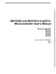
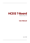
UART Modules
Master Station
A/D
UTXDn
ADD1 1
A/D
A/D
C0
ADD2 1
Transmitter
Enabled
USRn[TXRDY]
internal
module
select
C0
UMR1n[PM] = 11 ADD 1
UMR1n[PT] = 1
UMR1n[PT] = 0
ADD 2
UMR1n[PT] = 1
Peripheral Station
URXDn
A/D
A/D
0
ADD1 1
A/D
C0
A/D
A/D
ADD2 1
0
Receiver
Enabled
USRn[RXRDY]
internal
module
select
UMR1n[PM] = 11
ADD 1
Status Data
(C0)
Status Data
(ADD 2)
Figure 23-24. Multidrop Mode Timing Diagram
A character sent from the master station consists of a start bit, a programmed number of data bits, an
address/data (A/D) bit flag, and a programmed number of stop bits. A/D equals 1 indicates an address
character; A/D equals 0 indicates a data character. The polarity of A/D is selected through UMR1n[PT].
UMR1n should be programmed before enabling the transmitter and loading the corresponding data bits
into the transmit buffer.
In multidrop mode, the receiver continuously monitors the received data stream, regardless of whether it
is enabled or disabled. If the receiver is disabled, it sets the RXRDY bit and loads the character into the
receiver holding register FIFO provided the received A/D bit is a 1 (address tag). The character is
discarded if the received A/D bit is 0 (data tag). If the receiver is enabled, all received characters are
transferred to the CPU through the receiver holding register during read operations.
In either case, data bits load into the data portion of the FIFO while the A/D bit loads into the status portion
of the FIFO normally used for a parity error (USRn[PE]).
Framing error, overrun error, and break detection operate normally. The A/D bit takes the place of the
parity bit; therefore, parity is neither calculated nor checked. Messages in this mode may continues
containing error detection and correction information. If 8-bit characters are not required, one way to
provide error detection is to use software to calculate parity and append it to the 5-, 6-, or 7-bit character.
MCF52223 ColdFire® Integrated Microcontroller Reference Manual, Rev. 4
Freescale Semiconductor
23-25