1
F.1. OPAL-T COMPARED WITH TRANSPORT & TRACE 3D
235
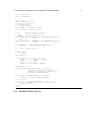
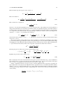
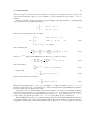
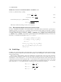
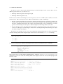
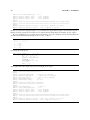
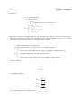
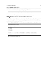
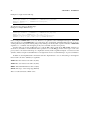
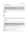
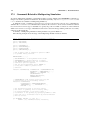
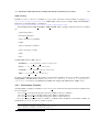
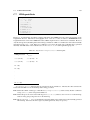
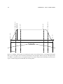
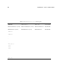
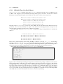
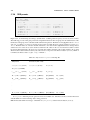
// Bending magnet configuration:
K1=0.0,
E1=10*Pi/180.0, E2=5* Pi/180.0,
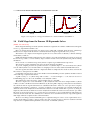
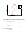
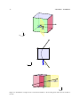
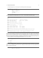
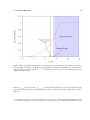
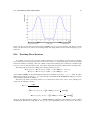
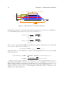
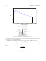
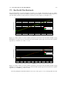
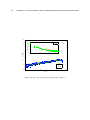
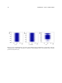
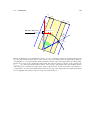
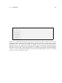
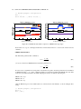
(a) Transverse beam size
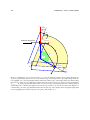
(b) Trasverse RMS emittance
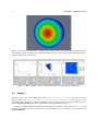
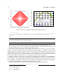
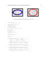
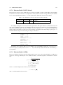
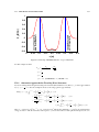
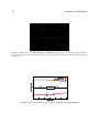
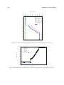
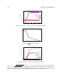
Figure F.11: TRACE 3D and OPAL comparison: SBEND with edge angles
Even in this case, a good overall agreement has been found between the two codes in term of beam size and
emittance.
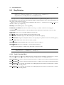
• SBEND with field index:
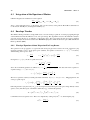
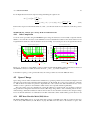
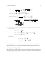
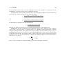
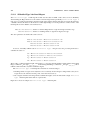
The field index parameter K1 is defined as:
K1 =
1 ∂By
,
Bρ ∂x
(F.4)
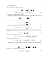
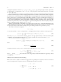
(see §8.4.1). Instead, in TRACE 3D the field index parameter n is:
n=−
ρ ∂By
.
By ∂x
(F.5)
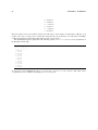
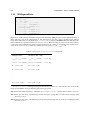
In order to have a significative focusing effect on both transverse planes, the transport line has been simulated
in TRACE 3D using n = 1.5. Since, a different definition exists between OPAL and TRACE 3D on the field
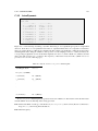
index, the n-parameter translation in OPAL language has been done with the following test:
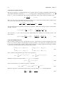
TEST 1: K1 = n/ρ2
TEST 2: K1 = n
TEST 3: K1 = n/ρ
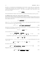
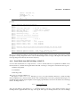
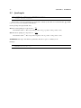
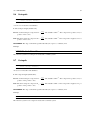
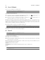
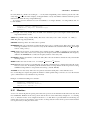
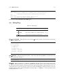
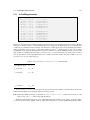
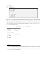
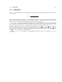
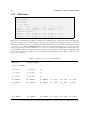
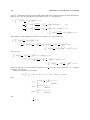
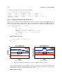
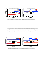
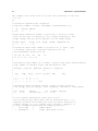
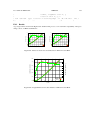
Only the TEST 2 reports a reasonable behaviour on the beam size and emittance, as shown in Figure F.12
using:
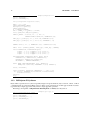
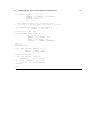
// Bending magnet configuration:
K1=1.5
E1=0, E2=0,