1
236
APPENDIX F. BENCHMARKS
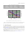
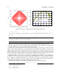
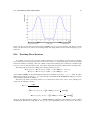
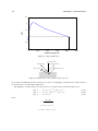
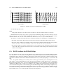
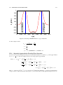
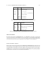
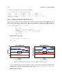
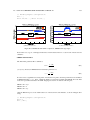
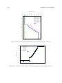
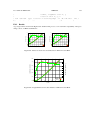
(a) Transverse beam size
(b) Trasverse RMS emittance
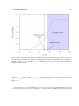
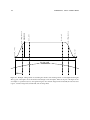
Figure F.12: TRACE 3D and OPAL comparison: SBEND with field index and default field map
Concerning the emittances and vertical beam size, a perfect agreement has been found, instead a defocusing
effect appears in the horizontal plane. These results have been obtained with the default field map provided
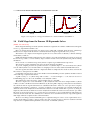
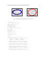
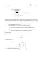
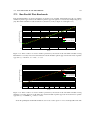
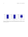
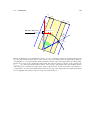
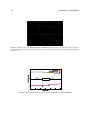
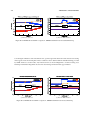
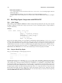
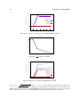
by OPAL. However, a better result, only in the beam size as shown in Figure F.13, is achieved using a test
field map in which the fringe field extension has been changed in the thin lens approximation.
(a) Transverse beam size
(b) Trasverse RMS emittance
Figure F.13: TRACE 3D and OPAL comparison: SBEND with field index and test field map