1
Appendix F
Benchmarks
F.1
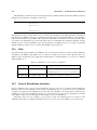
OPAL- T compared with TRANSPORT & TRACE 3D
F.1.1
TRACE 3D
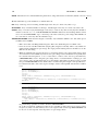
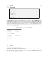
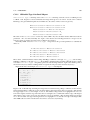
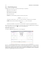
TRACE 3D is an interactive beam dynamics program that calculates the envelopes of a bunched beam, including
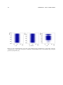
linear space-change forces [68]. It provides an instantaneous beam profile diagram and delineates the transverse
and longitudinal phase plane, where the ellipses are characterised by the Twiss parameters and emittances (total
and unnormalised).
F.1.2
TRACE 3D Units
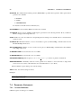
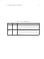
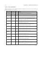
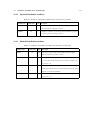
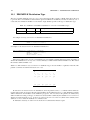
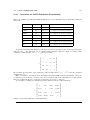
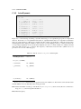
TRACE 3D supports the following internal coordinates and units for the three phase planes:
• horizontal plane:
x [mm] is the displacement from the center of the beam bunch;
x’ [mrad] is the beam divergence;
• vertical plane:
y [mm] is the displacement from the center of the beam bunch;
y’ [mrad] is the beam divergence;
• longitudinal plane:
z [mm] is the displacement from the center of the beam bunch;
∆p/p [mrad] is the difference between the particle’s longitudinal momentum and the reference momentum of
the beam bunch.
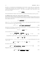
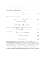
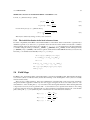
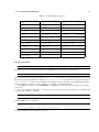
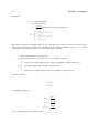
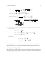
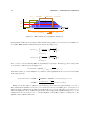
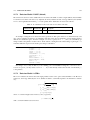
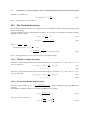
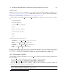
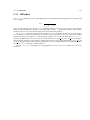
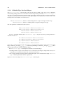
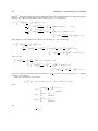
For input and output, however, z and ∆p/p are replaced by ∆φ [degree] and ∆W [keV], respectively the
displacement in phase and energy. The relationships between these longitudinal coordinates are:
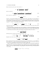
z=−
and
βλ
∆φ
360
∆p
γ ∆W
=
p
γ+1 W
(F.1)
(F.2)
where β and γ are the relativist parameters, λ is the free-space wavelength of the RF and W is the kinetic energy
[MeV] at the beam center. This internal conversion can be displayed using the command W (see [68] page 42).
223