1
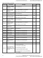
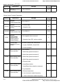
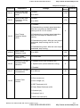
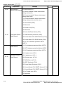
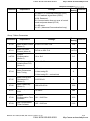
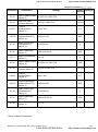
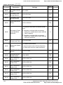
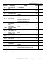
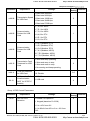
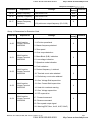
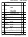
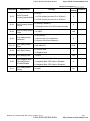
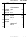
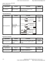
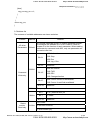
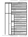
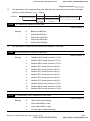
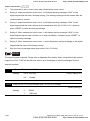
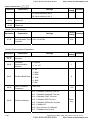
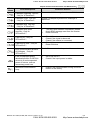
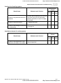
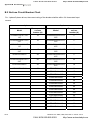
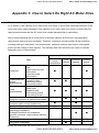
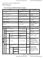
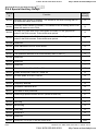
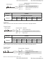
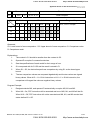
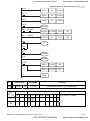
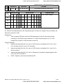
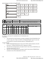
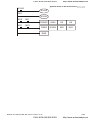
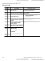
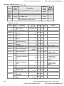
CALL NOW 800-985-6929
http://www.automatedpt.com
Chapter 4 Parameters|
Parameter
Explanation
Factory
Customer
Setting
Settings
23: Quick Stop (Only for VFD*E*C models)
24: Download/execute/monitor PLC Program
(PLC2) (NOT for VFD*E*C models)
25: Simple position function
26: OOB (Out of Balance Detection)
27: Motor selection (bit 0)
28: Motor selection (bit 1)
Group 12: Analog Input/Output Parameters for Extension Card
Parameter
Explanation
Factory
Customer
Setting
Settings
0: Disabled
1: Source of the 1st frequency
12.00
AI1 Function
Selection
2: Source of the 2nd frequency
0
3: PID Set Point (PID enable)
4: Positive PID feedback
5: Negative PID feedback
0: ACI2 analog current (0.0 ~ 20.0mA)
12.01
AI1 Analog Signal
Mode
12.02
Min. AVI3 Input
Voltage
0.0 to 10.0V
0.0
12.03
Min. AVI3 Scale
Percentage
0.0 to 100.0%
0.0
12.04
Max. AVI3 Input
Voltage
0.0 to 10.0V
10.0
12.05
Max. AVI3 Scale
Percentage
0.0 to 100.0%
100.0
12.06
Min. ACI2 Input
Current
0.0 to 20.0mA
4.0
12.07
Min. ACI2 Scale
Percentage
0.0 to 100.0%
0.0
1: AVI3 analog voltage (0.0 ~ 10.0V)
Revision Oct. 2009, 07EE, SW--PW V1.14/CTL V2.14
CALL NOW 800-985-6929
1
4-29
http://www.automatedpt.com