1
Printed Documentation
Table of Contents
Preface ..................................................................................................................... 1
1 The OCP User Interface ............................................................................................ 3
1 The Ortho Control Panel User Interface.................................................................... 3
1.1 Control Toolbar .................................................................................................. 3
2 Executing the Program ............................................................................................. 5
2 Executing the Program .......................................................................................... 5
2.1 System Settings ................................................................................................ 5
2.1 System Settings.............................................................................................. 5
2.1.1 OrthoAnalyzer .............................................................................................. 6
2.1.2 ApplianceDesigner ........................................................................................ 8
2.1.3 ScanItOrthodontics ....................................................................................... 8
2.1.4 ScanIt Ortho Impression ............................................................................... 9
2.1.5 Database ................................................................................................... 10
2.1.6 Export ....................................................................................................... 13
2.1.7 Miscellaneous............................................................................................. 18
2.1.8 Dongle Licence Server ................................................................................ 23
2.2 Administrative Settings ..................................................................................... 23
2.2 Administrative Settings .................................................................................. 23
2.2.1 Dongle Service ........................................................................................... 24
2.2.2 Communication .......................................................................................... 25
2.2.3 Sites ......................................................................................................... 25
2.3 Workflows Settings .......................................................................................... 26
3 Construction Elements ........................................................................................... 31
3 Construction Elements......................................................................................... 31
3.1 Template Base Models ...................................................................................... 31
3.2 Bars ............................................................................................................... 34
3.3 Attachments .................................................................................................... 37
3.4 Teeth Movement Constraints ............................................................................. 40
3.5 ID Tag Settings ............................................................................................... 40
4 Custom Report Configuration .................................................................................. 43
4 Custom Report Configuration ............................................................................... 43
4.1 Report Types ................................................................................................... 43
4.2 Report Templates............................................................................................. 45
5 Analysis set up ...................................................................................................... 47
6 Custom Analysis .................................................................................................... 49
6 Custom Report Configuration ............................................................................... 49
6.1 Custom Objects and Primitives .......................................................................... 49
6.2 Lookup Tables ................................................................................................. 53
6.3 Collections ...................................................................................................... 54
6.4 Questionnaires ................................................................................................ 61
6.5 Analysis Objects General Settings ...................................................................... 71
iii
Ortho Control Panel 2012
User Manual
Preface
3Shape Ortho Control Panel™ is the primary control tool for all the applications of 3Shape
Ortho Systems: ScanItOrthodontics™ and ScanIt Ortho Impression™, OrthoAnalyzer™,
ApplianceDesigner™ that allows you to view and manipulate various basic system settings
and controls, such as specifying data folders, tooth notation system, analysis tools and
licensing systems and the relevant construction elements.
OS-OCP-1.4.0.10-A-EN
1
1 The OCP User Interface
1 The Ortho Control Panel User Interface
Ortho Control Panel employs a Microsoft Windows™ -based graphical user interface that
allows you to view the settings modifications on screen while they are being made.
Ortho Control Panel is started by double-clicking the Ortho Control Panel desktop icon
or
via the Windows™ Start menu: Start → All Programs → 3Shape → 3Shape Ortho Control
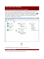
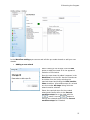
Panel. When the application is started, there appears a main window of the program
displayed on the image below. It consists of:
Control
toolbar
Main
2.
window
1.
A detailed description of the toolbars is provided in sections below.
1.1 Control Toolbar
The Control toolbar contains four basic control functions:
3
Printed Documentation
Displays the home
page.
Brings you back to
the previous step.
Saves the current
changes in the
settings.
Opens the user
manual.
4
2 Executing the Program
2 Executing the Program
3Shape Ortho Control Panel is started by double-clicking the Ortho Control Panel desktop
icon
or via the Windows™ Start menu: Start → All Programs → 3Shape → 3Shape Ortho
Control Panel. When the application is started, there appears the screen described and
illustrated in the previous chapter The Ortho Control Panel User Interface.
At this stage, there are options available for you as a starting point:
•
•
•
•
•
•
•
System settings
Workflow settings
Administrative settings
Construction elements
Custom report configuration
Standard analysis
Custom analysis
To continue, press the icons in the Main window:
Note: For any change to the Ortho Control Panel to take effect, it needs to be
saved in the Ortho Control Panel and the relevant application (i.e.
ApplianceDesigner, ScanItOrthodontics, ScanItOrthoImpression or OrthoAnalyzer)
has to be restarted.
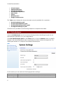
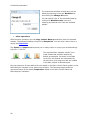
2.1 System Settings
2.1 System Settings
As soon as you click the System Settings icon, the main
window opens up displaying six tabs with different system
settings available for editing. You will have to scroll down
to view all of them:
5
Printed Documentation
•
•
•
•
•
•
•
•
OrthoAnalyzer
ApplianceDesigner
ScanItOrthodontics
ScanItOrthoImpression
Data folder
Export
Miscellaneous
Dongle license server
The Tasks menu displays the three main tasks currently available for completion:
•
•
•
•
Set
Set
Set
Set
OrthoAnalyzer path
ScanItOrthodontics path
ScanItOrthoImpression path
ApplianceDesigner path
Follow the hints provided in the following chapters to complete these tasks.
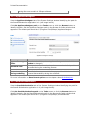
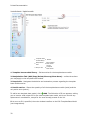
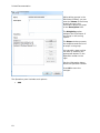
2.1.1 OrthoAnalyzer
View the OrthoAnalyzer tab of the System Settings window identifying the path for the
OrthoAnalyzer application in it (see image below).
Click Set OrthoAnalyzer path on the Tasks menu or click the Browse button to identify
the path. Set the OrthoAnalyzer path in the Browse for folder window that appeared. The
default path would be C:\Program Files\3Shape\OrthoAnalyzer.
OrthoAnalyzer settings
In this section you can make the following application settings:
Option
Ortho Analyzer
6
Function
The path to the folder, where Ortho Analyzer is installed. Use Browse
2 Executing the Program
folder
to change it.
Allows you to select from the drop-down menu the default position of
Standard view
the model during the modelling process.
Jaw state
Sets the default position of the jaw.
Allows the Model set compare function in Ortho Analyzer to
Cases compare
automatically run an alignment algorithm on the two models when
auto-alignment
starting the function.
If checked, uses the traditional two-dimensional measuring system,
Use 2D tooth
which would enable measuring dental distances using the user point-oflength
view as a measuring plane (1).
Save format
Allows you to select the format in which the model will be saved (2).
Use auto save
If checked, allows you to set the frequency with which the model will be
during modelling saved automatically during the workflow.
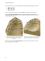
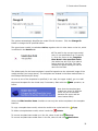
(1)
The method for placing the 2D (38.00) length
looks identical to that of the 3D length (51.33)
Illustration of the differences between the
2D (38.00) and the 3D (51.33) lengths
(2) The formats available for saving your models are:
Format
Option
STL
Standard open format.
3Shape compressed format. Gives smaller files, but not
DCM
supported by external software.
Only the raw scan points are saved. However, the points will still
PTS
be processed (temporarily) in order to allow alignment.
PTS Cyra Special point cloud format (for very special cases only).
VRML
Is an alternative format for saving models. It is primarily used for
7
Printed Documentation
saving face scan models in 3Shape software.
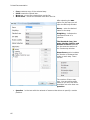
2.1.2 ApplianceDesigner
View the ApplianceDesigner tab of the System Settings window identifying the path for
the ScanItOrthodontics application in it (see image below).
Click Set ApplianceDesigner path on the Tasks menu or click the Browse button to
identify the path. Set the Appliance Designer path in the Browse for folder window that
appeared. The default path would be C:\Program Files\3Shape\ ApplianceDesigner
Appliance Designer settings
Option
Function
Appliance Designer The path to the folder, where Appliance Designer is installed. Use
folder
Browse to change it.
Allows you to select from the drop-down menu the default position of
Standard view
the model during the modelling process.
Save format
Allows you to select the format in which the model will be saved.
Use auto save
If checked, allows you to set the frequency with which the model will
during modelling
be saved automatically during the workflow.
For more information on Save format option see the chapter about OrthoAnalyzer.
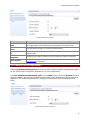
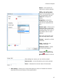
2.1.3 ScanItOrthodontics
View the ScanItOrthodontics tab of the System Settings window identifying the path for
the ScanIt Orthodontics application in it (see image below).
Click Set ScanItOrthodontics path on the Tasks menu or click the Browse button to
identify the path. Set the ScanItOrthodontics path in the Browse for folder window that
appeared. The default path would be C:\Program Files\3Shape\ SIOrthodontics.
8
2 Executing the Program
ScanIt Orthodontics settings
Option
Save raw scan
data
Cut and close
base
Reduce file size
to
Transform
maxillary
Save format
Function
Saves the intermediate results as raw (point cloud) data. This allows
you to get back to the scanning process without having the scan.
Cuts the base and align its contours automatically.
Define the extent of decimation (%) to visualize the scan decimation
along the way.
Transforms the upper model if only the maxillary model is scanned.
Sets the format in which the model will be saved (see the chapter
OrthoAnalyzer for details).
2.1.4 ScanIt Ortho Impression
View the ScanItOrthoImpression tab of the System Settings window identifying the path
for the ScanIt Ortho Impression application in it (see image below).
Click Set ScanItOrthoImpression path on the Tasks menu or click the Browse button to
identify the path. Set the ScanItOrthoImpression path in the Browse for folder window that
appeared. The default path would be C:\Program Files\3Shape\ ScanItOrthoImpression
beta\
ScanIt Ortho Impression settings
9
Printed Documentation
Option
Save raw scan
data
Reduce file size
to
Save format
Function
Saves the intermediate results as raw (point cloud) data. This allows you
to get back to the scanning process without having the scan.
Defines the extent of decimation (%) to visualize the scan decimation
along the way.
Allows to select the format for the scan (see chapter OrthoAnalyzer for
details).
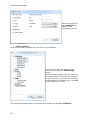
2.1.5 Database
View the Data folder tab of the System Settings window identifying the path for the
OrthoData in it. The OrthoData folder contains the input files for the 3Shape Orthoapplications.
Click the Browse button and set the OrthoData path in the Browse for folder window that
appeared. The default path would be C:\Program Files\3Shape\OrthoData.
Database settings
Option
Function
Microsoft SQL
Indicates the PC with the SQL server. You can change to another
Server location
PC by clicking Modify or Browse.
SQL Server Named Indicates the named instance of the SQL server on the PC. There
Instance
can be more than one SQL server named instances on one PC.
User
Indicates default user of the system (1).
Data folder
Indicates the path to the data folder.
(1) You can set the new password for a user and the SQL Server Named Instance
information by clicking the Modify button:
10
2 Executing the Program
Modifying additional parameters
It is possible to add some customized parameters to the Patient info, Model set info and
add list of Clinics in the following sections:
Setting parameters for Patient and Model set info and Clinics
Click the Add button to fill in customized information in the corresponding fields:
11
Printed Documentation
After adding a new item click the Default values button (1) to customize its parameters.
The Default values form popups. Click Add (2) to indicate the values (3). Click OK to save
them.
Mark the Automatic patient-ID checkbox to automatically generate the IDs:
Choose the number of characteristics by clicking at the arrows
option to the right.
in the characteristics
The Define template for ModelSet-ID generation section allows to edit the settings for
the models templates:
12
2 Executing the Program
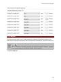
2.1.6 Export
The Export section allows you to make changes the settings for the Export option in the
Ortho System Appliance Designer and Ortho Analyzerfiles destination, unique file names etc.
Note: These parameters will apply to 3D models created via the Export Model
As
options in the Ortho Analyzer and Appliance Designer software , but also
to the Export features in the Ortho System Patient Browser.
1. Export Model as
13
Printed Documentation
Change file type / extension (STL or DCM) and Change file name (standard or unique ID).
2. Exporting Models, Patients or patients groups out of the Ortho System:
•
14
Export Patient from Patient Browser interface
2 Executing the Program
•
Export Model Set from Patient Browser interface
15
Printed Documentation
•
16
Export Patient Group
2 Executing the Program
Export section
Option
Use ModelSet folder for export
Use default export folder
Use qualified names when
exporting models
Function
If checked enables exporting files to Model Set folder.
This will apply all available Export options: Export to
File,
Export TRIOS Models without patched areas, Export to
CAMbridge, Export to ABO.
If checked allows you to set the path to the default
export folder (by clicking Browse).
If checked allows to give the exported models unique
names such as Patient and Model Set ID when
exporting models. If this is unchecked, the model sets
17
Printed Documentation
Export of TRIOS models with
patched areas into single
archive
will have standard names such as ‘Maxillary.XXX’ and
‘Mandibular.XXX’
If checked, enables exporting of TRIOS models with
patched areas into single archive.
2.1.7 Miscellaneous
This section allows you to set the additional parameters for the system.
18
2 Executing the Program
Miscellaneous settings
Option
Function
19
Printed Documentation
Allows you to set the language for the program (e.g. English,
French, etc.).
Indicates the Tooth index system that will be used in the
Tooth index system
applications (1).
Gradient background
Indicates the gradient background color of the top of the
color top
screen in the applications.
Gradient background
Sets the background color at the bottom of the screen in the
color bottom
application.
Basic model color
Sets the basic color for the model in the applications.
Shader material
Allows you to select the material for shader.
Defines the mode for the virtual texture visualization of the
Shader material for teeth
teeth (2).
Shader material for
Indicates the mode for the virtual texture visualization of the
tissue
tissue.
If checked, lists the patients by name, otherwise, they are
List patients by name
sorted by ID.
Allow patient and case
If checked, allows editing of patient information and case
info editing
information.
Allow patient and case
If marked, allows deleting of patient and case.
deleting
Allow multiple patients
Allows deleting of multiple patients and cases.
and cases deleting
Allow to export raw scan
Allows exporting raw scan data.
data
Automatic patients
When checked, OrthoAnalyzer automatically displays the list of
search when opening
patients when entering the Open patient form (so you don’t
form
have to press Search).
Default unprepared
Allows you to select the default action at double-clicking the
model set double click
unprepared model ( open or prepare model set).
action
Large previews
If selected, displays large previews in the applications.
Previews and
Allows you to set the format of the previews and screenshots.
screenshots format
Enable high resolution
models preview
If checked, enables high resolution models preview generator.
generator
High resolution preview Becomes active if the high resolution preview generator option
size
is enabled. You can set the parameters for the size of preview.
Save signed copies of
If checked saves the signed copies of scanned models.
scanned models
Allow updating patient
If checked, it is possible to update the patient info from
info from command line command line.
Language
(1) Select the appropriate Tooth index system out of the four possible options:
Universal Numeric Notation, FDI Notation, Haderup Notation and Palmer Notation.
Universal Numeric Notation:
20
2 Executing the Program
FDI Notation:
Haderup Notation (mostly used in Scandinavian and Eastern Europe countries):
Palmer Notation:
21
Printed Documentation
In the Ortho System, the mouth’s quadrants are identified using the following convention:
•
•
•
•
UR for Upper Right
UL for Upper Left
LR for Lower Right
LL for Lower Left
Thus, the Upper Right Central Incisor is called UR1 according to the Palmer notation.
Check the Use 2D tooth length checkbox to employ the traditional two-dimensional
measuring system, which would enable measuring dental distances using the user point-ofview as a measuring plane.
The method for placing the 2D (38.00) length
looks identical to that of the 3D length
(51.33)
Illustration of the differences between the
2D (38.00) and the 3D (51.33) lengths
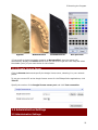
(2) Select the appropriate Shader material which would define the mode for the virtual
texture visualization of the models:
22
2 Executing the Program
Gypsum
ModelBackface
ModelBackface2
Not specified*
*If you prefer to leave the shader material as Not specified, then the system will
automatically display the Choose button that you can click to get the color map and select
the shader (color) of your own choice for the models.
2.1.8 Dongle Licence Server
Click the Browse button and specify the dongle license sever, selecting it in your network
places.
To set your current PC as the dongle license server for the 3Shape Ortho applications, click
This PC.
Specify the number of the Dongle license server port and click Test connection.
2.2 Administrative Settings
2.2 Administrative Settings
23
Printed Documentation
Administrative settings section allows you to set
administrative services like:
• Dongle Service
• Communication
• Sites
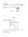
2.2.1 Dongle Service
As soon as you click the Administrative settings
icon, the main window opens up displaying the
Dongle update option (see image below). Click on
it to start updating your dongle.
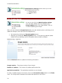
After you have clicked the Dongle Service tab, the main window opens up allowing you to
update the dongle in two ways (see the image below):
•
•
Via internet (by clicking the Internet update button).
Manually (by clicking the Manual update button). In this case the Manual update
window will pop up asking you for the update code provided by 3Shape.
Click the Refresh button to update the following information:
Dongle number – The unique number of your dongle.
Number of updates – The number of updates performed so far.
Applications enabled – The applications available on your dongle.
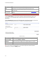
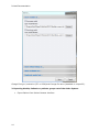
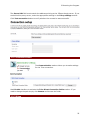
In order to update dongles via internet, click on the Connection setup button in the Tasks
menu. The image below illustrates the window that appears on the screen.
24
2 Executing the Program
The Server URL field must contain the address pointing at the 3Shape dongle server. If you
are behind the proxy server, enter the appropriate settings in the Proxy settings section.
Click Test connection button to verify whether the connection was successful.
2.2.2 Communication
The Communication section allows you to make settings
for the Trios connection.
Mark Enable checkbox to activate the Trios Direct Connection Folder section. If you
need to change the path simply click Browse and choose the folder.
2.2.3 Sites
25
Printed Documentation
The Sites section allows you to customize interactions
between Ortho System and labs, manufacturers or clinics.
Using this section will ease transferring orders process
from the current site to the central manufacturing site.
Edit site section
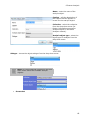
2.3 Workflows Settings
As soon as you click the Workflow settings icon, the
main window opens up offering you to edit the workflow
steps (see the image below).
The application allows you to setup a number of customized workflow wizards with
predefined operational steps in OrthoAnalyzer. This cleans up the software interface and
organizes steps and operations for your own use.
26
2 Executing the Program
In the Workflow settings you can use and edit the pre-made wizards or add your new
wizards.
•
Adding a new wizard
When creating a new wizard, click the Add
button to add the wizard ID in the appeared
Selection of ID window.
Once the new wizard is added it appears in the
Workflow list on the left. Inactive wizards can
be hidden from the list by selecting the
required wizard and ticking the Hide inactive
items checkbox. All available steps of a wizard
are show under All steps listing while the
wizard remains selected.
Select the required steps for the created
wizard and transfer them to the Current
workflow steps list on the right with the
button. Use the
button to
remove the selected steps from the Current
workflow steps list if needed.
27
Printed Documentation
The customized workflow wizard name can be
edited by selecting it from the Workflow list
and clicking the Change ID button.
You can specify color of the selected wizard by
clicking the Workflow color cube and
selecting the desired color from the available
palette.
•
Other operations
With the other operations you can Copy, Delete, Move up and Move down the selected
wizards. The deleted wizards are kept in the Recycle bin. You can either restore them or
empty the Recycle bin.
The Export and Import buttons allow you to easily export or import your wizard settings
to/from a *.3ml file.
Preparation
VirtualSetup
Analyzer
The supplied Ortho software installs 3 premade customized workflow wizards by
default as examples. As shown in the table
to the left, the wizards are represented by
the hat icons of varying color and are located
in the Main toolbar of OrthoAnalyzer.
Only the sequence of steps defined for the wizard in the Ortho Control Panel appears in the
OrthoAnalyzer interface on the wizard icon selection. The following image shows the
operational steps of the default Preparation wizard in the Ortho Control Panel and
OrthoAnalyzer interfaces:
28
2 Executing the Program
29
3 Construction Elements
3 Construction Elements
The Construction elements section contains the
templates and settings for the
• Template base models
• Bars
• Attachments
• Teeth Movement Constraints
• ID Tag Settings
Click at the appropriate icons will take to these
sections.
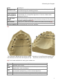
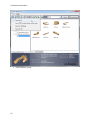
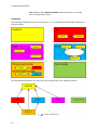
3.1 Template Base Models
Template base model – Enlists entries for the template base models.
Manipulation field (Add/Copy/Delete/Move up/Move down) - enlists the actions you
may apply to the template base models.
Recycle bin - Navigates the deletion and restoration process regarding the template base
models entries.
Details - Show the quantity of all the template base models (total) and the only active ones
(active).
31
Printed Documentation
Template base
4. Details
models library
Edit template
Manipulation
2.
5. base model
field
section
Template
3. Recycle bin
6.
base model
1.
1. Template base models library – Enlists entries for the template base models.
2. Manipulation field (Add/Copy/Delete/Move up/Move down) - enlists the actions
you may apply to the template base models.
3. Recycle bin - Navigates the deletion and restoration process regarding the template
base models entries.
4. Details section - Shows the quantity of all the template base models (total) and the
only active ones (active).
Add. The Selection of ID box appears, asking
To add a new template base model, click
you to insert a valid unique ID for the new template base model, which can involve any
alphanumeric combination, except for the ones already present in the list.
5. As soon as ID is specified, the main window transfers to the Edit Template Base Model
(see image above).
32
3 Construction Elements
The system automatically identifies the model ID with its name. Click the Change ID
button to change the ID specified before.
The upper-base 1model is marked as Active, together with 11 other items on the list, which
is reflected in the Details tab.
6. The path for the current base model
entry is not specified at first. To specify
it, move the cursor to the Template
Base Model <Not specified field>
(the white box will circle it to make it
active) and click the field. The Open
window will appear asking for the file
name for the base.
The default path for the base templates is specified opposite to the schematic image of the
model selected (see image above). The templates are located in the Base models folder in
the 3Shape OrthoAnalyzer library.
As soon as one of the templates is specified (in our case, the upper model), go on to add
Add operation, as
the second template for the virtual cast, if necessary. Start with the
before.
Note that the template base
models are shown in different
colors for you to associate
between the upper and the
lower basses easily.
Select the Hide inactive items checkbox to see only the active templates in the template
base list.
To copy a template base model, select the model to be copied and click
To delete a template base model, select it and click
Copy.
Delete.
To move a template base model up in the list, select it and click
To move a template base model down in the list, select it and click
Move up.
Move down.
33
Printed Documentation
Follow the scheme below to navigate the various options in the Recycle bin:
3.2 Bars
Bars are 3D construction components based on a predefined 2D profiles which can
be used to create appliances in Appliance Designer. Follow the instructions to
arrange settings for bars.
34
3 Construction Elements
1. Create a bar
Bar settings
Click the
Add button and enter the ID of the item. The Edit Bars section is activated. It
is possible to change the ID of the created item and the Name ( for more information see
the section Template Base models).
2. Customize the item settings
Select the Bar shape type from the drop-down menu:
35
Printed Documentation
Each type has specific further settings. For instance, Custom type allows to edit the
parameters of the Shape spline coordinates manually.
Click at the coordinates and type the desired numbers. In either case you
can scroll the wheel on your mouse to change the parameters.
Customize the scale of the spline in the Scale editbox. It is possible to observe the results
of editing on the grid in the Shape spline image section.
It is possible to create a spline of any shape you
like. Add extra points by double-clicking at the
grid. You can move the red point to any position
you like by holding the left button of the mouse.
Right-click the point to open the popup menu and
remove a point. Select Interactive control
point to be able to operate with the selected
point in the Appliance Designer.
Snap to grid - allows to fixate the points on the grid.
Mark the Symmetric shape checkbox to keep the spline automatically symmetric.
Customize the look of the spline grid by setting the parameters in the Shape spline image
grid spacing editbox.
36
3 Construction Elements
Select the Ending type from the drop-down menu:
•
•
Flat - creates flat ends on the bar
Wrap Around - creates rounded ends with the shape wrapped around the vertical
axis.
Optional degrees of freedom section - enables the indicated bar transformations in
ApplianceDesigner during editing.
Save your settings by clicking the Save
button in the Main menu.
3.3 Attachments
Attachments section allows you to set the parameters for the attachments
in OrthoAnalyzer. Click the corresponding icon on the Home page to open
the Attachments page.
37
Printed Documentation
1. Create an attachment
Attachment settings
Click the
Add button to create an attachment. Enter the ID of the item and click OK in
the popup window. Now you can set the parameters for the new item. Choose the type of
attachment from the following options:
Visual model - an attachment setup as visual model will be displayed on the screen but
will have no impact on the underlying geometry, unless one of the two following options is
chosen:
•
Additive models: when this option is chosen, the attachment geometry will be
added to the underlying model’s geometry (Boolean operation)
•
Subtractive models: when this option is chosen, the attachment geometry will be
subtracted from the underlying model’s geometry (Boolean operation)
OR
2 . Customize the attachment settings
38
3 Construction Elements
It is possible to change the ID and Name of the item (for more information see the
section Template base models).
Indicate the path of the model in the Attachment visual model path, Attachment
additive model path and Attachment subtractive model path that will be displayed
together with the preview of the attachment. Once you click at the desired section the Open
window appears, where you select the CAD file (.stl, .dcm, .wrl).
Select the Default orientation of the attachment from the drop-down menu:
Mark the Tilt checkbox to set the parameters for the inclination of the attachment axis in
the Max tilt editbox.
Translate from surface option, if checked, allows to set the Max distance of the
attachment movements in the corresponding editbox.
Mark Rotation around axis checkbox to perform rotation of the attachment around its
axis.
The Scale in x (y, z) direction checkbox, if checked, allows stretching of the attachment
along the corresponding axis.
Note: All attachments need to be part
of a Group to be available in
OrthoAnalyzer or Appliance Designer.
To make attachments available in the OrthoAnalyzer or Appliance Designer applications, it is
necessary to include them in Attachment Groups. Click the
new group:
Add button to create a
Type the name of the new group and click OK. The new group window can be filled with the
attachments. To add the attachment to the group select it with a single click from the
Attachment tab and click the
Add current attachment button.
39
Printed Documentation
3.4 Teeth Movement Constraints
The Teeth Movement Constraints option allows you to set
the parameters for the teeth movements you perform in
OrthoAnalyzer. Constraints can be associated with
biomechanical values for given tooth groups, or for example to
specific appliances or treatment methods.
The settings for the Teeth Movement Constraints tab are the same as in the Bars and
Attachments section.
It is possible to set the parameters for the group of teeth.
Follow the instructions in the right column and use the
appropriate buttons to Create a new group, Select a group,
Change a group. Mark Use symmetry checkbox to select
opposing group of teeth. The teeth will be highlighted by
different colors. After selecting the group you can set the
parameters of the movement constraints for the whole group.
Double click the numbers in the
Teeth Movements Constraints
table to edit the parameters for
each type of movement of every
tooth.
3.5 ID Tag Settings
The ID Tag Settings section allows you to set the
parameters for the ID tags that can be placed on 3D
models in Appliance Designer.
An ID tag can either be:
positive
integrated
in the
model’s
surface
40
negative
3 Construction Elements
or it can be
detachable
1. Create a new ID tag
Use the Add
button to create the new ID tag. You can change its ID and Name in the
Edit ID Tag Settings section.
Indicate the Text that will appear on the ID tag.
2. Set the parameters for each type of ID tag
Indicate the Font Depth and Font Height of the Integrated or Detachable types of ID tags
in the corresponding edit boxes.
41
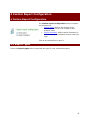
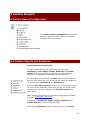
4 Custom Report Configuration
4 Custom Report Configuration
The Custom report configuration section contains
two subsections:
• Report types: defines the content of the
report, chosen from a list of features and
analysis items
• Report templates: defines which framework is
used to display the elements chosen under the
type.
Click at any subsection to open it.
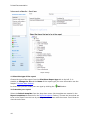
4.1 Report Types
Select the Report types tab to create/edit the type for your customized report:
43
Printed Documentation
Report settings
1. Select the type of the report
Choose the type of the report from the Primitives-Report type tab to the left. It is
possible to Change the ID and the Name of the report type (for more information see the
chapter Template Base Models).
In either case you can create your own type by clicking the
Add button.
2. Customize your report
Select the Default template from the drop down menu (the templates are created in the
Report templates tab descried in the Report templates section). Choose the items that are
to be in the report from the tree by marking the checkboxes with the mouse. Scroll down to
view the entire tree.
44
4 Custom Report Configuration
Note: choose the Model Image option from the list for each view in order
to show the study models.
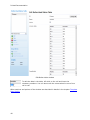
4.2 Report Templates
You can create a report template in the Report templates section. Click the appropriate
icon in the Custom report configuration section to open the following window:
Report templates settings
Click the Browse button to select the path to the report template from the Browse for Files
or Folders window that appears on the screen.
Other sections and options of the window are described in details in chapter Construction
Elements.
45
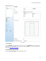
5 Analysis set up
The Analysis set up tab deals with the setup of
the following standard analysis tables which are
used as references in some analysis workflows:
•
•
•
Standard tooth width tables
Standard Moyers tables
Standard Bolton tables
Click on any of the icons to begin editing. The
image below illustrates the editing of the
Standard Bolton tables. The Standard tooth
width tables and the Standard Moyers tables
are edited in the same way.
47
Printed Documentation
Edit Bolton table window
To edit the data in the table, left-click on the cell and insert the
necessary numbers. You can also scroll the mouse wheel to move from
cell to cell.
Other sections and options of the window are described in details in the chapter Template
Base Models.
48
6 Custom Analysis
6 Custom Report Configuration
The Custom Report configuration tab presents
the tools required to fully customize analyses,
questionnaires, and reports.
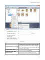
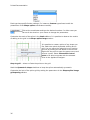
6.1 Custom Objects and Primitives
Custom objects and Primitives
For your customized analyses and report you can setup
Landmarks, Lines, Angles, Planes, Distances and Custom
splines. Click on any of the colored icons to open an editing
window. The image below illustrates the editing of lines.
You can add a line by clicking the Add button and give a name to
you new line. Name your line as desired and select two landmarks
(or points) for it (Landmark 0 and Landmark 1).
Select the Use 2D projection checkbox to use a projection plane
on which to take measures, rather than directly on the 3d model.
You can select the type of plane in the Projection plane dropdown menu.
Other sections and options of the window are described in details
in chapter Construction Elements.
The editing of Landmarks, Angles, Planes, Distances and
Custom splines follows the same principal.
When editing Distances, keep in mind that there is a point-to
49
Printed Documentation
line distance and a point-to-plane distance that you can choose
from the drop-down menu.
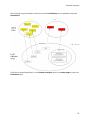
Primitives
The following illustration shows the primitives, i.e. the conceptual relationships between the
defined objects:
The dependencies between the primitives are summarized in the following picture:
X
50
Y means X depends on Y
6 Custom Analysis
Example: Korkhaus-Schwartz Analysis: a custom
analysis has been created in your installed system
and we will use it as a working example of the
concepts applied to the custom objects and
analyses (image to the left).
Landmarks, Angles, Distances and Custom splines sections have almost the same
settings as
•
planes:
51
Printed Documentation
Operation
buttons
2. List of planes
3. Recycle Bin
1.
1. Customize the available planes
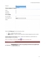
Click Add to create the new plane and enter the ID for it:
Otherwise, click Copy to duplicate the existing plane. It is possible to give a new name to
the copy.
Select To Recycle bin to delete the plane from the list.
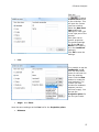
2. Edit the List of planes
52
6 Custom Analysis
Double click the Name or ID of the plane to edit the appropriate field. Double click the
Landmark 1(2,3) section to select the landmark type from the drop-down menu (see the
image above).
3. Work in the Recycle bin
button you open the list of the items in the Recycle bin.
After clicking the
It is possible to select to
it or Empty the Recycle bin.
the particular item or to
. Otherwise Delete
to exit the Recycle bin.
Click
All the options are available in the pop-up menu after right-clicking the list.
6.2 Lookup Tables
To create a reference lookup table for your analysis workflow, go to
the Lookup Tables tab to open an editing window (see the image
below).
53
Printed Documentation
A Lookup Table with 5 columns and 19 rows was defined with values from the following
website: http://www.johnsdental.com/articles/ortho/Scwzkork1.htm
To create a new table, click the
Add button and name your table as desired (e.g.
Schwarz-Korkhaus). Enter the necessary amount of columns and rows in the corresponding
fields, choose the amount of columns and click Apply. After the table has been created, you
can modify it by left-clicking on the columns and entering the respective values.
Other sections and options of the window are described in details in chapter Construction
Elements.
6.3 Collections
In the Collections tab you can create a group of different primitives –
landmarks, lines, angles, planes, distances, splines and object values,
which will typically correspond to the full analysis protocol you want to
create.
54
6 Custom Analysis
The following image illustrates collections and how Primitives can be applied to separate
Collections:
Click the corresponding button in the Custom analysis section on Home page to open the
Collections tab:
55
Printed Documentation
To customize the collections follow the steps described below.
Step 1: Create a collection
To create a collection, click the
Add button and name your collection as desired. Select
to add them to your
different elements from the drop down menus and click
to delete an element from the collection. You can Export and
collection. Click
Import the collection with the help of the corresponding buttons (see the image above).
It is possible to edit the ID and Name of the selected collection ( for more information see
the section Template base models).
Step 2: Customize the collection
You can observe the elements forming the selected collection in the Collection objects
tab. It is possible to fold/unfold the groups by clicking the triangle in front of the name of
the group.
Use the operation buttons to the right to customize the collection or right click the selected
object in the collection elements tree.
56
6 Custom Analysis
Click the
button
to add a new element
to the collection. This
will open the Create
new item window.
Select the New item
type and fill the
settings for each type
in the right part of the
window.
Each item has its
specific properties.
The general settings
will be the ID and
Name of the object (
as in the Landmark
settings).
Click OK to save the
settings.
•
Line
It is possible to set the
Landmark1 and 2
from the drop-down
menu for the new line
from the existing
ones. Click the New
button to create the
new landmark. The
Create new item
window for landmark
appears (see the
previous image). You
can set the
Projection plane for
the line you create.
•
Angle
and Plane
Have the same settings as the Line but for the Projection plane.
•
Distance
57
Printed Documentation
Set the properties for
the Landmark and
Line as in the
appropriate sections.
• Custom splines
Have the same list of settings the Line but for the Landmarks.
It is possible to add new element to the
collection by clicking the Add existing
button.
The Info window appears with the list of the
elements available. Select the element from
the collection tree by single click or holding
the Ctrl button for multiple choice. Click OK
to add the items to the list.
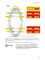
The Korkhaus Schwartz analysis Collection thus includes the following Primitives:
58
6 Custom Analysis
A set of 7 landmarks set by the user on the specific teeth (e.g. Korkhaus_UR4, Korkhaus_U1_1...)
4 lines: Korkhaus B, defined Korkhaus_U4_4, joining the landmarks Korkhaus_UR4 and
Korkhaus_UL4 etc.; and 1 Distance: Korkhaus_D, which joins the Korkhaus_B line and the
landmark Korkhaus_U1_1.
Please note that a primitive can be applied in several Collections or analyses.
At the bottom of the window there is an Object Values
button where you can create some fixed values or associate
some calculations to the Primitives you have defined in
your Collection. The image below illustrates the Edit Object
Values window that contains the items of the expression and
the white field of the expression itself.
59
Printed Documentation
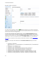
To create a new expression, click the
Add button and name your collection as desired.
Click on the necessary buttons in the table to select the desired items for your expression in
the drop-down menu (see image above).
To check if the expression was created correctly, click the Check expression button. A
small information window will appear informing you whether the expression was created
correctly or there was an error. Check the Always return result checkbox to return to the
default value in case of the expression failure (the Default value can be entered below.
Other sections and options of the window are described in details in chapter Construction
Elements.
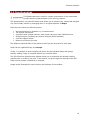
Specifically, the object values defined for the Korkhaus-Schwartz analysis are listed
below:
•
•
•
•
•
•
•
•
•
60
Korkhaus_A: Expression:
ToothWidthPN('UR1')+ToothWidthPN('UL1')+ToothWidthPN('UR2')+ToothWidthPN('U
L2')
Korkhaus_B: Line: Korkhaus_U4_4
Korkhaus_C: Line: Korkhaus_U6_6
Korkhaus_B_ideal: Lookup('Schwartz-Korkhaus','B,B1',Korkhaus_A)
Korkhaus_C_ideal: Lookup('Schwartz-Korkhaus','C',Korkhaus_A)
Korkhaus_D_ideal: Lookup('Schwartz-Korkhaus','D',Korkhaus_D)
Korkhaus_B-B_ideal_discrepency: Expression: Korkhaus_B-Korkhaus_B_ideal
Korkhaus_C-C_ideal_discrepency: Expression: Korkhaus_C-Korkhaus_C_ideal
Korkhaus_D-D_ideal_discrepency: Expression: Korkhaus_D-Korkhaus_D_ideal
6 Custom Analysis
6.4 Questionnaires
The Questionnaires are used for a better presentation of the customized
analysis and the implementation of the scoring systems.
The Questionnaire is a powerful feature that allows you to present your customized analyses
in a user-friendly manner by arranging them in a logical sequence of Steps.
Each step can contain the following items:
•
•
•
•
•
•
Imported pictures to illustrate e.g. a measurement
The written instructions
A question with multiple choices, each answer having its own individual score
Analysis objects (including any custom analysis object available)
A screen capture button
Notes to be filled by the user
The default model and state of the patient model can also be preset for each step.
Steps can be organized freely into Groups.
Finally, it is possible to enter weights and scores for the individual steps and groups,
thereby making it easy to compute indexes e.g. the PAR Index.
The Edit Primitives-Questionnaire window allows you to customize the already existing
questionnaire or create a new one. In this section, we go through the settings of the PAR
Index scoring system included as an example.
Image below illustrates the main sections and toolbars of the window:
61
Printed Documentation
1.
2.
3.
4.
The Questionnaire list
Editing Toolbar
Recycle bin
Details
5.
6.
7.
8.
Name and ID section
List of Questions and Question Groups
Operation Toolbar
Main menu
1. The Questionnaire list presents the list of the questionnaires available for
viewing/editing. You can hide inactive items in the list by ticking the appropriate option
under this window.
2. The Editing Toolbar allows you to add new questionnaires, copy and delete them, move
questionnaires up/down in the list above and export or import questionnaires.
3. The Recycle bin shows the number of the items removed and allows to restore the
items or empty the bin altogether.
4. The Details section presents the information about the total number of items loaded and
the number of active items.
62
6 Custom Analysis
5. The Name and ID section presents the name of the questionnaire and its ID.
You can change the ID by selecting the
•
button.
•
Type the new ID into the ID field and click
OK.
•
To change the questionnaire name, type the
desired name into the corresponding filed.
6. The List of Questions and Question Group presents the list of Groups and Steps.
You can fold/unfold each group by clicking at the
arrow in front of the group name.
To edit a step or the whole group, perform one of
the following actions:
•
Right click on the step/group and select
Edit from the appeared menu.
•
Double click on the name of a step/group
to open the Edit Step/Edit Group forms
respectively.
•
Select a desired step/group and choose
the Edit button from the Operation
toolbar to open the Edit Step/Edit
Group forms respectively.
63
Printed Documentation
While editing groups in the
Edit Group window, you can
enter the Name of the Group
as well as type in the
information about the group
in the Description field.
The Weighting option
indicates the importance of
the Group in the scoring
system.
The Steps window presents
the sequence and the list of
all steps in the group.
You can edit a step and the
list itself by selecting the
appropriate buttons in the
Operation toolbar to the
right.
See the information below
about the Operation toolbar.
Press OK to save the
changes.
The Operation panel includes such options:
•
64
Add
6 Custom Analysis
To create a step, select the Add
button on the Operation toolbar.
The Create step window includes:
Name - insert the desired name for
the step.
Weighting - insert a number for
the scoring weight for the step.
Standard view - contains the drop
down menu with the model
visualization options:
Jaw state - contains the drop down
menu with the jaw visualization
options:
Models visibility - lets you choose
the upper/lower or both models
from the drop down menu:
Default collection - allows you to
select the appropriate collection. For
further information see the
OrthoAnalyzer™ 2010 user manual
(section Analysis Objects).
•
•
Edit allows making some changes to the step you have created.
Delete removes the steps.
65
Printed Documentation
•
•
•
•
Copy creates a copy of the selected step.
Paste inserts the copied item.
Move up - moves the selected item up the list.
Move down - moves the selected item down the list.
After selecting the Edit
option for the step you will
open the Edit step window.
Name – enter the desired
name for the step.
Weighting - indicates the
importance level of a
question.
The Standard view, Jaw
state, Models visibility and
Default collection sections
are the same as sections in
the Create step window.
Steps items section includes
the number of features that
make up each step. There
can be:
The number of items may
vary. You can add as many
items as you like, still there
should be not more than one
Question.
•
66
Question - is the text with the variants of answers that allows to specify a certain
problem.
6 Custom Analysis
Name - is the section for
naming the certain question.
Text - is the space where
you can type the question
itself. The exclamation mark
will be displayed near the
Text field as long as it
empty.
Weighting - shows the
importance of the question
that will be summed at the
end.
Answer type - allows you to
select the type in which the
variants of an answer will be
presented either as a list, a
drop-down menu or ratio
buttons.
Select the appropriate type
from the drop down menu.
Integer - stands for unified
numerals.
Float - stands for nonintegral numerals.
Answers section - shows
the list of the answers.
button to
Use the Add
create a new variant or the
button to remove
Delete
it.
After adding the answer you can edit its content.
Answer text - is the information given as the answer.
Score - indicates the numeral value of the answer.
•
Hint bitmap - allows you to select and display a picture to illustrate the actions
required at the current setup of the questionnaire.
67
Printed Documentation
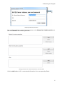
If you select the Edit or Add button you will open the Add hint bitmap window:
Name - enter the name of the hinting bitmap.
The width and height of the bitmap can be
changed by clicking on the up/down arrows in
the editing window.
To load the bitmap, press the Load bitmap
button and select the picture you want to
upload. The supported formats are .jpg, .bmp,
.png. If the bitmap is not loaded you will see
the exclamation mark near the editing
window.
The picture will be displayed in the Bitmap
preview to the left.
•
Hint text
You can type the name of
the hinting text in the
appropriate section.
It is possible to add a
description.
•
68
Hint analysis object
6 Custom Analysis
Name - enter the name of the
analysis object.
Caption - edit the description of
the caption that will appear on
screen for the analysis object.
Collection - select the collection
from the drop-down menu (for
further information see section
Analysis objects in the Ortho
Analyzer manual).
Analysis object type - select the
object type for analysis from the
drop down menu:
Subtype - choose the object subtype from the drop down menu:
Note: For the predefined Collections, the dropdown menu shows the available analysis
objects:
•
Screenshot
69
Printed Documentation
Type in the name and the
description of the
screenshot to be taken by
the user and click OK to save
changes.
•
Note
This field allows you to
create a space in which the
user can write notes in the
current step of the analysis.
Type in the name and the
description of the caption
and click OK to save
changes.
You can also edit the already existing items of a step. The form is the same as in adding
items.
7. The Operation toolbar allows to manage the Groups and Steps:
Add step adds steps to the selected group.
Delete step removes the selected group or step.
Add group allows you to add a new group.
Delete group removes a selected group.
Copy step creates a copy of a selected step.
Paste step allows to insert a copied step.
Edit opens the editing window.
Move up moves the selected group or step up the list.
Move down moves the selected group or step down the list.
8. The Main menu allows you to save the changes in the questionnaire file. Select the
Save button in the main menu.
After setting the questionnaire in the Control Panel and saving the changes, you can now
open it in Ortho Analyzer™ .
70
6 Custom Analysis
Note: Restart Ortho Analyzer™ if it was opened at the moment
of editing the Questionnaire in the Control Panel for the changes
to take effect.
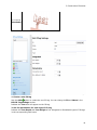
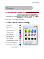
6.5 Analysis Objects General Settings
Allows you to select the color for the enlisted objects by
clicking the appropriate square section and choosing the
desired color from the popping up palette. Click the Reset
to default button to undo the selection:
71