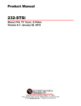
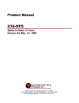
1
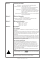
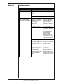
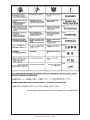
®
Owner’s Manual
Product:
CobraCooler®
Manual:
091-0609
Serial:
09100001
Voltage Rating: 100/120/208/
240VAC
Revision:
Sept 2009 Rev A
Model Number: 250-153
Table of Contents
Safety Guidelines..................................................................................................i-vi
Technical Information................................................................................. Section 1
Electrical Information.................................................................................. Section 2
Mechanical Information.............................................................................. Section 3
Connections............................................................................................... Section 4
Weldhead...................................................................................................................................... 1
CobraTig® 150 Latches................................................................................................................. 1
Operation . ................................................................................................. Section 5
Coolant.......................................................................................................................................... 2
Accessories................................................................................................ Section 6
Weldhead Extension Cable.......................................................................................................... 2
Spare Parts................................................................................................ Section 7
Fuse.............................................................................................................................................. 2
Coolant Flow Filter........................................................................................................................ 2
Flow Rate................................................................................................... Section 8
Troubleshooting.......................................................................................... Section 9
Troubleshooting Guide.................................................................................................................. 4
Appendix.................................................................................................. Section 10
Diagrams/Parts List...................................................................................................................... 5
Safety Warnings
Warranty
Declaration of Conformity for
European Community (CE) Products
Note
This information is provided for units with CE certification (see rating label on unit).
Manufacturer’s Name:
MK Products, Inc.
16882 Armstrong Ave.
Irvine, CA 92606
Declares that the product:
®
CobraCooler
Python®
conforms to the following Directives and Standards:
Directives
Low Voltage Directive: 73/23/EEC
Electromagnetic Compatibility (EMC) Directive: 89/336/EEC
Standards
Arc Welding Equipment Part I: Welding Power Sources: IEC 60974-1
(September 1998 - Second Edition)
Arc Welding Equipment: Wirefeed Systems: IEC 974-5
(September 1997 - Draft Revision)
Degrees of Protection Provided by Enclosures (IP Code): IEC 529:1989
(November 1989 - First Edition)
Insulation Coordination For Equipment With Low-Voltage Systems:
Part I: Principles, Requirements and Tests: IEC 664-1: 1992
(October 1992 - First Edition)
Electromagnetic Compatibility, (EMC): EN 50199
(August 1995)
Torches And Guns For Arc Welding, EN 50078
SAFETY CONSIDERATIONS
ELECTRIC ARC WELDING EQUIPMENT
CAUTION : READ BEFORE ATTEMPTING INSTALLATION, OPERATION
OR MAINTENANCE OF THIS EQUIPMENT
1-1 INTRODUCTION
This equipment is intended for ultimate
application by commercial/industrial
users and for operation by persons
trained and experienced in the use and
maintenance of welding equipment.
Operation should not be undertaken
without adequate training in the use of
such equipment. Training is available
from many public and private schools or
similar facilities.
Safe practices in the installation, operation and maintenance of this equipment
requires proper training in the art, a
careful study of the information provided
with the equipment, and the use of
common sense. Rules for safe use
are generally provided by suppliers of
welding power sources, compressed
gas suppliers, and electrode suppliers.
Careful compliance with these rules will
promote safe use of this equipment.
The following Safety Rules cover some
of the more generally found situations.
READ THEM CAREFULLY. In case of
any doubt, obtain qualified help before
proceeding.
1-2 GENERAL PRECAUTIONS
A. Burn Prevention
ELECTRIC ARC WELDING PRODUCES
HIGH INTENSITY HEAT AND ULTRAVIOLET RADIANT ENERGY WHICH
MAY CAUSE SERIOUS AND PERMANENT EYE DAMAGE AND WHICH
MAY DAMAGE ANY EXPOSED SKIN
AREAS.
Wear helmet with safety goggles or
glasses with side shields underneath,
appropriate filter lenses or plates (protected by clear cover glass). This is a
must for welding or cutting (and chipping)
to protect the eyes from radiant energy
and flying metal. Replace cover glass
when broken, pitted, or spattered.
Medical first aid and eye treatment. First
aid facilities and a qualified first aid
person should be available for each shift
unless medical facilities are close by for
immediate treatment of flash burns of
the eyes and skin burns.
Wear protective clothing - leather (or
asbestos) gauntlet gloves, hat, and high
safety-toe shoes. Button shirt collar and
pocket flaps, and wear cuffless trousers
to avoid entry of sparks and slag.
Avoid oily or greasy clothing. A spark
may ignite them.
Flammable hair preparations should not
be used by persons intending to weld
or cut.
Hot metal such as electrode stubs and work
pieces should never be handled without
gloves.
Ear plugs should be worn when working
on overhead or in a confined space. A
hard hat should be worn when others work
overhead.
B. Toxic Fume Prevention
WARNING: The use of this product may
result in exposure to chemicals known
to the State of California to cause cancer
and birth defects or other reproductive
harm.
Adequate ventilation. Severe discomfort,
illness or death can result from fumes,
vapors, heat, or oxygen enrichment or
depletion that welding (or cutting) may
produce. Prevent them with adequate
ventilation. NEVER ventilate with oxygen.
Lead-, cadmium-, zinc-, mercury-, beryllium-bearing and similar materials, when
welded or cut, may produce harmful concentrations of toxic fumes. Adequate local
exhaust ventilation must be used, or each
person in the area, as well as the operator,
must wear an air-supplied respirator. For
beryllium, both must be used.
Metals coated with or containing materials
that emit toxic fumes should not be heated
unless coating is removed form the work
surface, the area is well ventilated, or the
operator wears an air-supplied respirator.
Work in a confined space only while it is
being ventilated and, if necessary, while
wearing an air-supplied respirator.
Causes of fire and explosion are: combustibles reached by the arc, flame,
flying sparks, hot slag, or heated material, misuse of compressed gases and
cylinders, and short circuits.
BE AWARE THAT flying sparks or falling
slag can pass through cracks, along
pipes, through windows or doors, and
through wall or floor openings, out of
sight of the goggled operator. Sparks
can fly many feet.
To prevent fires and explosion:
Keep equipment clean and operable,
free of oil, grease, and (in electrical
parts) of metallic particles that can cause
short circuits.
If combustibles are in area, do NOT weld
or cut. Move the work if practicable,
to an area free of combustibles. Avoid
paint spray rooms, dip tanks, storage
areas, ventilators. If the work cannot
be moved, move combustibles at least
35 feet away, out of reach of sparks and
heat; or protect against ignition with
suitable and snug-fitting, fire-resistant
covers or shields.
Walls touching combustibles on opposite
sides should not be welded on (or cut).
Walls, ceilings, and floor near work
should be protected by heat-resistant
covers or shields.
Fire watcher must be standing by with
suitable fire extinguishing equipment
during and for some time after welding
or cutting if:
Gas leaks in a confined space should be
avoided. Leaked gas in large quantities can
change oxygen concentration dangerously.
Do not bring gas cylinders into a confined
space.
1. Appreciable combustibles (including
building construction) are within 35 feet.
Leaving confined space, shut OFF gas
supply at source to prevent possible accumulation of gases in the space if downstream valves have been accidentally
opened or left open. Check to be sure that
the space is safe before reentering it.
3. Openings (concealed or visible) in
floors or walls within 35 feet may expose
combustibles to sparks.
Vapors from chlorinated solvents can be
decomposed by the heat of the arc (or
flame) to form PHOSGENE, a highly toxic
gas, and other lung and eye irritating products. The ultraviolet (radiant) energy of the
arc can also decompose trichloroethylene
and perchloroethylene vapors to form
phosgene. DO NOT WELD or cut where
solvent vapors can be drawn into the
welding or cutting atmosphere or where
the radiant energy can penetrate to atmospheres containing even minute amounts of
trichloroethylene or perchloroethylene.
C. Fire and Explosion Prevention
CobraCooler® Safety - Page i
2. Appreciable combustibles are further
than 35 feet, but can be ignited by
sparks.
4. Combustibles adjacent to walls, ceilings, roofs, or metal partitions can be
ignited by radiant or conducted heat.
Hot work permit should be obtained
before operation to ensure supervisor’s
approval that adequate precautions have
been taken.
After work is done, check that area is
free of sparks, glowing embers, and
flames.
An empty container that held combustibles, or that can produce flammable or
toxic vapors when heated, must never
be welded on or cut, unless container
has first been cleaned in accordance
with industry standards.
This includes: a thorough steam or
caustic cleaning (or a solvent of water
washing, depending on the combustible’s
solubility), followed by purging and inerting with nitrogen or carbon dioxide, and
using protective equipment.
Water-filling just below working level may
substitute for inerting.
A container with unknown contents
should be cleaned (see paragraph
above). Do NOT depend on sense of
smell or sight to determine if it is safe to
weld or cut.
Hollow castings or containers must be
vented before welding or cutting. They
can explode.
Explosive atmospheres. NEVER weld
or cut where the air may contain flammable dust, gas, or liquid vapors (such
as gasoline).
D. Compressed Gas Equipment
The safe handling of compressed gas
equipment is detailed in numerous industry publications. The following general
rules cover many of the most common
situations.
1. Pressure Regulators
Regulator relief valve is designed to
protect only the regulator from overpressure; it is not intended to protect
any downstream equipment. Provide
such protection with one or more relief
devices.
tent. Notify supplier if unmarked. NEVER
DEFACE or alter name, number, or other
markings on a cylinder. It is illegal and
hazardous.
Empties: Keep valves closed, replace caps
securely; mark MT; keep them separate
from FULLS, and return promptly.
Prohibited use. Never use a cylinder or its
contents for other than its intended use,
NEVER as a support or roller.
Locate or secure cylinders so they cannot
be knocked over.
Passageways and work areas. Keep cylinders clear of areas where they may be
stuck.
Transporting cylinders. With a crane, use
a secure support such as a platform or
cradle. Do NOT lift cylinders off the ground
by their valves or caps, or by chains, slings,
or magnets.
Do NOT expose cylinders to excessive
heat, sparks, slag, and flame, etc. that may
cause rupture. Do not allow contents to
exceed 55 degrees C (130 degrees F.)
Cool with water spray where such exposure
exists.
Protect cylinders, particularly valves from
bumps, falls, falling objects, and weather.
Replace caps securely when moving cylinders.
Stuck valve. Do NOT use a hammer or
wrench to open a cylinder valve that cannot
be opened by hand. Notify your supplier.
Never connect a regulator to a cylinder
containing gas other than that for which
the regulator was designed.
Mixing gases. NEVER try to mix any gases
in a cylinder.
Remove faulty regulator from service
immediately for repair (first close cylinder
valve). The following symptoms indicate
a faulty regulator:
Cylinder fittings should never be modified
or exchanged.
Leaks - if gas leaks externally.
Excessive Creep - if delivery pressure
continues to rise with downstream valve
closed.
Faulty Gauge - if gauge pointer does
not move off stop pin when pressurized,
nor returns to stop pin after pressure
release.
Repair. Do NOT attempt repair. Send
faulty regulators for repair to manufacturer’s designated repair center, where
special techniques and tools are used
by trained personnel.
2. Cylinders
Cylinders must be handled carefully to
prevent leaks and damage to their walls,
valves, or safety devices:
Avoid electrical circuit contact with cylinders including third rails, electrical wires,
or welding circuits. They can produced
short circuit arcs that may lead to a serious accident. (See 1-3C)
ICC or DOT marking must be on each cylinder. It is an assurance of safety when
the cylinder is properly handled.
Identifying gas content. Use only cylinders with name of gas marked on them;
do not rely on color to identify gas con-
NEVER refill any cylinder.
3. Hose
Prohibited use. Never use hose other
than that designed for the specified gas.
A general hose identification rule is: red
for fuel gas, green for oxygen, and black
for inert gases.
Use ferrules or clamps designed for the
hose (not ordinary wire or other substitute)
as a binding to connect hoses to fittings.
No copper tubing splices. Use only standard brass fittings to splice hose.
Avoid long runs to prevent kinks and abuse.
Suspend hose off ground to keep it from
being run over, stepped on, or otherwise
damaged.
away from people and sources of ignition.
Wipe with a clean, lintless cloth.
Match regulator to cylinder. Before
connecting, check that the regulator label
and cylinder marking agree, and that the
regulator inlet and cylinder outlet match.
NEVER Connect a regulator designed
for a particular gas or gases to a cylinder
containing any other gas.
Tighten connections. When assembling
threaded connections, clean and smooth
seats where necessary. Tighten. If
connection leaks, disassemble, clean,
and retighten, using properly fitting
wrench.
Adapters. Use a CGA adapter (available
from your supplier) between cylinder
and regulator, if one is required. Use
two wrenches to tighten adapter marked
RIGHT and LEFT HAND threads.
Regulator outlet (or hose) connections
may be identified by right hand threads
for oxygen and left hand threads (with
grooved hex on nut or shank) for fuel
gas.
5. Pressurizing Steps:
Drain regulator of residual gas through
suitable vent before opening cylinder
(or manifold valve) by turning adjusting
screw in (clockwise). Draining prevents
excessive compression heat at high
pressure seat by allowing seat to open
on pressurization. Leave adjusting
screw engaged slightly on single-stage
regulators.
Stand to side of regulator while opening
cylinder valve.
Open cylinder valve slowly so that regulator pressure increases slowly. When
gauge is pressurized (gauge reaches
regulator maximum) leave cylinder valve
in following position: for oxygen and inert
gases, open fully to seal stem against
possible leak; for fuel gas, open to less
than one turn to permit quick emergency
shut-off.
Use pressure charts (available from
your supplier) for safe and efficient
recommended pressure settings on
regulators.
Check for leaks on first pressurization
and regularly thereafter. Brush with
soap solution. Bubbles indicate leaks.
Clean off soapy water after test; dried
soap is combustible.
Coil excess hose to prevent kinks and
tangles.
E. User Responsibilities
Protect hose from damage by sharp edges,
and by sparks, slag, and open flame.
Remove leaky or defective equipment
from service immediately for repair. Read
and follow user manual instructions.
Examine hose regularly for leaks, wear, and
loose connections. Immerse pressured
hose in water; bubbles indicate leaks
Repair leaky or worn hose by cutting area
out and splicing. Do NOT use tape.
4. Proper Connections
Clean cylinder valve outlet of impurities that
may clog orifices and damage seats before
connecting regulator. Except for hydrogen,
crack valve momentarily, pointing outlet
CobraCooler® Safety - Page ii
Follow all Safety Rules.
F. Leaving Equipment Unattended
Close gas supply at source and drain
gas.
G. Rope Staging-Support
Rope staging-support should not be
used for welding or cutting operation;
rope may burn.
1-3 ARC WELDING
Comply with precautions in 1-1, 1-2,
and this section. Arc Welding, properly
done, is a safe process, but a careless
operator invites trouble. The equipment
carries high currents at significant voltages. The arc is very bright and hot.
Sparks fly, fumes rise, ultraviolet and
infrared energy radiates, weldments
are hot, and compressed gases may
be used. The wise operator avoids
unnecessary risks and protects himself
and others from accidents.
A. Burn Protection
Comply with precautions in 1-2.
The welding arc is intense and visibly
bright. Its radiation can damage eyes,
penetrate lightweight clothing, reflect
from light-colored surfaces, and burn
the skin and eyes. Skin burns resemble
acute sunburn; those from gas-shielded
arcs are more severe and painful. DON’T
GET BURNED; COMPLY WITH PRECAUTIONS.
1. Protective Clothing
Wear long-sleeve clothing in addition to
gloves, hat, and shoes. As necessary,
use additional protective clothing such
as leather jacket or sleeves, flameproof
apron, and fire-resistant leggings. Avoid
outer garments of untreated cotton.
Bare skin protection. Wear dark, substantial clothing. Button collar to protect
chest and neck, and button pockets to
prevent entry of sparks.
2. Eye and Head Protection
Protect eyes from exposure to arc. Eyes
may be damaged by radiant energy
when exposed to the electric arc, even
when not looking in the direction of the
arc. Never look at an electric arc without
protection.
Welding helmet or shield containing a
filter plate shade no. 12 or denser must
be used when welding. Place over face
before striking arc.
Protect filter plate with a clear cover
plate.
Cracked or broken helmet or shield
should NOT be worn; radiation can be
passed through to cause burns.
Cracked, broken, or loose filter plates
must be replaced IMMEDIATELY.
Replace clear cover plate when broken,
pitted, or spattered.
Flash goggles with side shields MUST
be worn under the helmet to give some
protection to the eyes should the helmet
not be lowered over the face before
an arc is struck. Looking at an arc
momentarily with unprotected eyes
(particularly a high intensity gas-shielded
arc) can cause a retinal burn that may
leave a permanent dark area in the field
of vision.
3. Protection of Nearby Personnel
Enclose the welding area. For production
welding, a separate room or enclosed
bay is best. In open areas, surround the
operation with low-reflective, noncombustible screens or panels. Allow for free air
circulation, particularly at floor level.
ity. Be sure conductors are touching
bare metal of equipment frames at connections.
Viewing the weld. Provide face shields for
all persons who will be looking directly at
the weld.
If a line cord with a ground lead is
provided with the equipment for connection to a switch box, connect the ground
lead to the grounded switch box. If a
three-prong plug is added for connection
to a grounded mating receptacle, the
ground lead must be connected to the
ground prong only. If the line cord comes
with a three-prong plug, connect to a
grounded mating receptacle. Never
remove the ground prong from a plug, or
use a plug with a broken ground prong.
Others working in area. See that all persons
are wearing flash goggles.
Before starting to weld, make sure that
screen flaps or bay doors are closed.
B. Toxic Fume Prevention
Comply with precautions in 1-2B.
Generator engine exhaust must be vented
to the outside air. Carbon monoxide can
kill.
C. Fire and Explosion Prevention
Comply with precautions in 1-2C.
Equipment’s rated capacity. Do not overload arc welding equipment. It may overheat cables and cause a fire.
Loose cable connections may overheat or
flash and cause afire.
Never strike an arc on a cylinder or other
pressure vessel. It creates a brittle area that
can cause a violent rupture or lead to such a
rupture later under rough handling.
D. Compressed Gas Equipment
Comply with precautions in 1-2D.
E. Shock Prevention
Exposed electrically hot conductors or
other bare metal in the welding circuit, or in
ungrounded, electrically - HOT equipment
can fatally shock a person whose body
becomes a conductor. DO NOT STAND, SIT,
LIE, LEAN ON, OR TOUCH a wet surface
when welding without suitable protection.
To protect against shock:
Keep body and clothing dry. Never work
in damp area without adequate insulation
against electrical shock. Stay on a dry
duckboard, or rubber mat when dampness
or sweat cannot be avoided. Sweat, sea
water, or moisture between body and an
electrically HOT part - or grounded metal
- reduces the body surface electrical resistance, enabling dangerous and possibly
lethal currents to flow through the body.
1. Grounding the Equipment
When installing, connect the frames of
each unit such as welding power source,
control, work table, and water circulator to
the building ground. Conductors must be
adequate to carry ground currents safely.
Equipment made electrically HOT by stray
currents may shock, possibly fatally. Do
NOT GROUND to electrical conduit, or to a
pipe carrying ANY gas or a flammable liquid
such as oil or fuel.
Three-phase connection. Check phase
requirement of equipment before installing. If only three-phase power is available,
connect single-phase equipment to only two
wires of the three-phase line. Do NOT connect the equipment ground lead to the third
(live) wire, or the equipment will become
electrically HOT - a dangerous condition
that can shock, possibly fatally.
Before welding, check ground for continuCobraCooler® Safety - Page iii
2. Connectors
Fully insulated lock-type connectors
should be used to join welding cable
lengths.
3. Cables
Frequently inspect cables for wear,
cracks, and damage. IMMEDIATELY
REPLACE those with excessively worn
or damaged insulation to avoid possibly
lethal shock from bared cable. Cables
with damaged areas may be taped to
give resistance equivalent to original
cable.
Keep cable dry, free of oil and grease,
and protected from hot metal and
sparks.
4. Terminals and Other Exposed
Parts
Terminals and other exposed parts of
electrical units should have insulating
covers secured before operation.
5. Electrode Wire
Electrode wire becomes electrically HOT
when the power switch of gas metal-arc
welding equipment is ON and welding
gun trigger is pressed. Keep hands
and body clear of wire and other HOT
parts.
6. Safety Devices
Safety devices such as interlocks and
circuit breakers should not be disconnected or shunted out.
Before installation, inspection, or service
of equipment, shut OFF all power, and
remove line fuses (or lock or red-tag
switches) to prevent accidental turning
ON of power. Disconnect all cables from
welding power source, and pull all 115
volts line-cord plugs.
Do not open power circuit or change
polarity while welding. If, in an emergency, it must be disconnected, guard
against shock burns or flash from switch
arcing.
Leaving equipment unattended. Always
shut OFF, and disconnect all power to
equipment.
Power disconnect switch must be available near the welding power source.
Thank You
For selecting a quality product. We want you to take
pride in operating this product...as much pride as we
have in bringing the product to you!
Please Examine Carton and Equipment For Damage Immediately
When this equipment is shipped, title passes to the purchaser upon receipt by the
carrier. Consequently, claims for material damaged in shipment must be made by the
purchaser against the transportation company at the time the shipment is received.
Please record your equipment identification information below for future reference. This
information can be found on your machine nameplate.
Model Name & Number
_____________________
Code & Serial Number
_____________________
Date of Purchase
_____________________
Whenever you request replacements parts for, or information on this equipment always
supply the information you have recorded above.
Read this Owner’s Manual completely before attempting to use this equipment. Save this manual
and keep it handy for quick reference. Pay particular attention to the safety instructions we
have provided for your protection.
Section 1
Technical Information
Line Power: 120, 230VAC 50/60 HZ, Single Phase ONLY
Reservoir Capacity:Approximately 1 gal / 3.78 l
On level surface, fill per requirements indicated on
the site gauge on front of the CobraCooler®.
Coolant Type: Use Cobra® Coolant (Aluminum Protection), P/N
931-0060. Cobra® Coolant does not contain reactive
sulphur or chlorine and does not react with copper,
brass or aluminum.
System Pressure: Maximum system pressure is 21.75 PSI as specified
by the pump manufacturer.
Section 2
Electrical Information
Pump: 12 Volt DC, 2 amps
AC Power for Cooling Unit: Panel switchable, rear panel fuse holder
Front Panel Indicators: Spinning Flow Indicator
Section 3
Mechanical Information
Dry Weight:
Height:
Width:
Depth:
Section 4
13.9 lbs. / 6.30 kg
5.5 in. / 14.0 cm
8.5 in. / 21.6 cm
19 in. / 48.3 cm
Connections
4.1 Weldhead
The CobraCooler® is designed to be used with CopperHead® model orbital
weldheads.
The connectors on the rear panel of the CobraCooler® include the coolant IN/
OUT (bottom/top) female quick-disconnect connectors. The male connectors
from a water-cooled orbital weldhead can be attached to this unit in any
configuration.
These coolant connectors are a double-end shut off valve type. This means,
if the cooler is turned on and there is nothing plugged into these connectors,
no fluid will flow out of the connector. Similarly, the connectors on the end of
the weldhead hose work in the same manner. No fluid will flow from the end
of the hose unless it is plugged into the cooler.
4.2 CobraTig® 150 Latches
The CobraCooler® easily attaches to the bottom of the CobraTig® 150
using a four corner-mounted spring-locked latches. These latches are
already mounted to the four outside corners of the CobraCooler®. Place
the CobraTig® 150 on top of the CobraCooler®, so that all sides are even
and flush. Lift the finger handle of the latch and raise the spring up over the
shoulder-washer on the CobraTig® 150. Press down on the finger handle
until the locking spring engages.
Lift the finger handle to test the locking spring. Repeat process on all four
latches.
CAUTION
DO NOT ATTEMPT TO LIFT THE UNIT UNTIL ALL FOUR LATCHES ARE
LOCKED.
To disengage the CobraTig® 150 press on the locking spring and lift the finger
handle until the spring is released from the shoulder-washer.
CobraCooler® Owner’s Manual - Page 1
Section 5
Operation
5.1 Coolant
CAUTION
COOLANT MUST BE ADDED PRIOR TO OPERATING.
From the top of the CobraCooler®, open the access panel, unscrew the fill
plug and pour in the coolant.
DO NOT SPILL COOLANT INTO THE UNIT.
An electrical short may occur if coolant is spilled into the unit
It is recommended that all coolant be removed from the CobraCooler® prior to
shipping. After draining, some coolant may still remain in the internal pump,
radiator, filter, and circulatory tubing.
Section 6
Accessories
Weldhead Extension Cable
Weldhead extension cable, P/N 005-0635. It comes complete with all the
necessary cabling to adapt the MK orbital weldheads: control cable with 24
pin connector, electrode and ground cables, inert gas hose and water hose
assembly with quick-disconnect connectors. This 25 ft. extension cable is to
mate any of the MK CopperHead® series weldheads to the CobraCooler®. A
50 ft is also available under P/N 005-0635-50.
Section 7
Spare Parts
7.1 Fuse
WARNING
DISCONNECT UNIT FROM ALL POWER SOURCES PRIOR TO
CHANGING FUSE.
ELECTRIC SHOCK CAN KILL
Located on the rear panel of the CobraCooler® is a 0.50 amp BUSS fuse.
If the unit does not turn on with the power switch, check the integrity of the
fuse.
Turn the fuse cap on the front panel and remove fuse. Check fuse using
continuity meter. Replace if necessary.
7.2 Coolant Flow Filter
WARNING
DISCONNECT UNIT FROM ALL POWER SOURCES PRIOR TO
CHANGING MESH FILTER.
ELECTRIC SHOCK CAN KILL
Periodically, the mesh-screen filter may require cleaning and/or replacement.
Replaceable Parts List
Description
Part Number
Fuse
151-0043
Mesh Filter
567-0012
CobraCooler® Owner’s Manual - Page 2
Section 8
Flow Rate
Flow Rate with MK Weldhead (25 FT Total)*
Flow Rate with MK Weldhead and 25 FT Extension (50 FT Total)*
Flow Rate with MK Weldhead and 50 FT Extension (75 FT Total)*
*All testing done with MK Products CopperHead® weldheads
CobraCooler® Owner’s Manual - Page 3
Section 9
Troubleshooting
Symptom
CobraCooler® does not
turn on.
The Flow Indicator is not
rotating. Indicating that
the coolant is not flowing.
Troubleshooting
Cause
Remedy
CobraCooler® is not
plugged into an electrical
outlet.
Plug the CobraCooler®
into an electrical outlet.
The external fuse failed.
Replace fuse.
The male connectors from
the water-cooled orbital
weldhead are not properly
connected to the
CobraCooler®.
Connect both male
connectors fully to the
female quick-disconnect
connectors that are
located on the back side
of the CobraCooler®.
The pump is not primed.
Elevate the front face of
the CobraCooler® to
assist the flow of coolant
into the pump. After flow
is indicated, return the
CobraCooler® to
horizontal. Let the
CobraCooler® run for a
few minutes to expel any
air pockets that may still
be present in the system.
The weldhead is above
the CobraCooler® beyond
the workable range as
illustrated in Section 8.
Reduce the vertical
distance of the weldhead
and the CobraCooler® to
a workable range.
The weldhead and/or
extensions has not been
used previously used and
the weldhead was
elevated 15 ft above the
CobraCooler® before the
lines were filled with
coolant.
Lower the weldhead to
the level of the
CobraCooler®. Let the
CobraCooler® run for a
few minutes, with the
weldhead at this level, to
expel any air pockets that
may still be present in the
system.
CobraCooler® Owner’s Manual - Page 4
Section 10
Appendices
Diagrams/Parts List
CobraCooler® Assy...................................................................... 6
Bill of Material.............................................................................. 7
CobraCooler® Owner’s Manual - Page 5
CobraCooler® Assembly
CobraCooler® Owner’s Manual - Page 6
CobraCooler® Owner’s Manual - Page 7
No. Qty Part No.
26
2 341-0069
27
8 341-0075
28
2 342-0111
29
2 342-0479
30
2 342-0561
31
1 405-0887
32
1 405-1086
33
14 411-0271
34
2 411-0294
35
4 415-0077
36
2 435-1243
37
1 435-1244
38
1 436-0167
39
1 438-0082
40
2 438-0083
41 5 ft 551-0450
42 1.23 ft 551-0451
43
1 567-0012
44
2 753-0152
45
2 753-0153
46
47
48
1 843-0666
49
1 861-0003
CobraCooler
No. Qty Part No. Description
1
1 003-2358 Assy Fan CobraCooler
2
1 003-2359 Assy Motor Pump CobraCooler
3
1 003-2362 Assy Tank 1 Gallon CobraCooler
4
1 003-2363 Assy LED CobraCooler
5
1 003-2364 Assy Fuse CobraCooler
6
1 159-0132 Switch Rocker Panel Mount DPST 16A 250V
7
1 003-2401 Assy Flow Indicator
8
1 191-0016 Power Supply 12V 40W Open
9
1 201-0027 Fan Filter Screen
10 1 201-0028 Wire Form Fan Guard
11
5 301-0103 Bumper Pad Rubber
12 .22 ft 261-0006 Wrap SPL 3/8 OD Black
13 4 315-0023 Bushing Keeper
14 1 315-0696 Strain Relief Bushing .625 DIA
15 4 319-0283 Screw Flat PH Head 82Deg 8-32 x 1/2 SST
16 4 329-0415 Screw Hex 1/4-20 5.0 SST
17 4 331-0092 Washer Flat #8 SST
18 2 333-0261 Washer Spring Lock #8 SST
19 4 333-0263 Washer Lock Spring 1/4 SST
20 4 336-0105 Screw PH 4-40 x 3/16 SST
21 18 336-0128 Screw PH Mach Phil 8-32 SST 1/4IN
22 9 336-0130 Screw PH Mach PHil 3-32 SST 3/8IN
23 4 339-0003 Screw Cheese Head Slot M3.5 x 10MM SST
24 4 339-0006 Screw Cheese Head Slot M3.5 x 20MM SST
25 2 341-0063 Nut Hex 4-40 SST
Assy Power Cable CobraCooler
Radiator Bare Black W/MTG
Description
Nut Hex 8-32 SST
Nut Hex 1/4-20 SST
Spacer 1/2OD .166ID 3/16
Standoff Fem 1/4Hex 4-40 x 1/2 Nylon
Standoff Fem 1/4Hex 8-32 x 1 Alum
Decal Warning
Serial Plate
Clamp Worm Scr 1/8-3/8 ID
Clamp Cable 3/8 Dia Nylon Black
Latch Spring Chassis Locking
C-Bar CobraCooler
Window View CobraCooler
SS Base CobraCooler
Paint Cover CobraCooler
Paint Door Access CobraCooler
Hose 1/4ID x 3/8OD Poly Blue
Hose 3/8ID x 9/16OD Poly Blue
Filter Inline 1/4 Barb Low
Coupler DS 1/4 Barb Panel
FTTG Reduce CPLG 3/8 x 1/4
CobraCooler® Owner’s Manual - Page 8
CobraCooler® Owner’s Manual - Page 9
LIMITED WARRANTY
Effective August 1, 2008
This warranty supersedes all previous MK Products warranties and is
exclusive, with no other guarantees or warranties expressed or implied.
LIMITED WARRANTY - MK Products Inc., Irvine, California warrants
that all new and unused equipment furnished by MK Products is free
from defects in workmanship and material as of the time and place of
delivery by MK Products. No warranty is made by MK Products with
respect to trade accessories or other items manufactured by others.
Such trade accessories and other items are sold subject to the warranties of their respective manufacturers, if any.
MK Products’ warranty does not apply to components having normal
useful life of less than one (1) year, such as relay points, wire conduit,
tungsten, and welding gun parts that come in contact with the welding
wire, including gas cups, gas cup insulators, and contact tips where
failure does not result from defect in workmanship or material.
MK Products shall, exclusively remedy the limited warranty or any
duties with respect to the quality of goods, based upon the following
options:
(1) repair
(2) replacement
(3) where authorized in writing by MK Products, the reasonable cost
of repair or replacement at our Irvine, California plant.
As a matter of general policy only, MK Products may honor an original
user’s warranty claims on warranted equipment in the event of failure
resulting from a defect within the following periods from the date of
delivery of equipment to the original user:
1. Power Supplies and Wire Feed Cabinets ..................3 years
2. Weldheads, CobraCooler, Positioners, Prince XL and
Prince XL Spool Guns, Python, CobraMAX, Cobra SX,
Cobra MX ....................................................................1 year
3. Sidewinder Spool Gun, Prince SG Spool Guns, Modules ......
............................................................................... 180 days
4. Repairs/Exchanges/Parts/Accessories .................. 90 days
16882 Armstrong Ave.
Irvine, CA 92606
Tel (949) 863-1234
Fax (949) 474-1428
www.mkproducts.com
16882 Armstrong Ave.
Irvine, CA 92606
Tel (949) 863-1234
Fax (949) 474-1428
www.mkproducts.com
Classification of any item into the foregoing categories shall be at the
sole discretion of MK Products. Notification of any failure must be made
in writing within 30 days of such failure.
A copy of the invoice showing the date of sale must accompany products
returned for warranty repair or replacement.
All equipment returned to MK Products for service must be properly
packaged to guard against damage from shipping. MK Products will
not be responsible for any damages resulting from shipping.
Normal surface transportation charges (one way) for products returned
for warranty repair or replacement will be borne by MK Products, except
for products sold to foreign markets.
ANY EXPRESS WARRANTY NOT PROVIDED HEREIN AND ANY IMPLIED
WARRANTY, GUARANTY, OR REPRESENTATION AS TO PERFORMANCE,
AND ANY REMEDY FOR BREACH OF CONTRACT WHICH, BUT FOR
THIS PROVISION, MIGHT ARISE BY IMPLICATION, OPERATION OF
LAW, CUSTOM OF TRADE, OR COURSE OF DEALING, INCLUDING ANY
IMPLIED WARRANTY OF MERCHANTABILITY OR OF FITNESS FOR
PARTICULAR PURPOSE, WITH RESPECT TO ANY AND ALL EQUIPMENT
FURNISHED BY MK PRODUCTS, IS EXCLUDED AND DISCLAIMED BY
MK PRODUCTS.
EXCEPT AS EXPRESSLY PROVIDED BY MK PRODUCTS IN WRITING,
MK’s PRODUCTS ARE INTENDED FOR ULTIMATE PURCHASE BY COMMERCIAL/INDUSTRIAL USERS AND FOR OPERATION BY PERSONS
TRAINED AND EXPERIENCED IN THE USE AND MAINTENANCE OF
WELDING EQUIPMENT AND NOT FOR CONSUMERS OR CONSUMER
USE. MK PRODUCTS’ WARRANTIES DO NOT EXTEND TO, AND NO
RE-SELLER IS AUTHORIZED TO EXTEND MK PRODUCTS’ WARRANTIES
TO ANY CONSUMER.
USE OF OTHER THAN GENUINE MK PRODUCTS’
CONSUMABLES, PARTS, AND ACCESSORIES MAY INVALIDATE YOUR
PRODUCT WARRANTY.
August 1, 2008
Rev. A
August 1, 2008
Rev. A
THIS PAGE INTENTIONALLY BLANK
16882 ARMSTRONG AVE.
IRVINE,CALIFORNIA 92606
(949) 863-1234 • FAX (949) 474-1428
www.mkproducts.com