1
CURRICULUM
TSLC
Mechanical Engineering
(Pre-SLC Intake)
Council for Technical Education and Vocational Training
Curriculum Development Division
Sanothimi, Bhaktapur
(Developed in 1991, First Revision 1999, Second Revision 2007)
Third Revision 2014
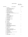
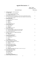
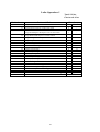
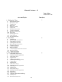
Table of Contents
Introduction: __________________________________________________________________________ 4
Aims: ________________________________________________________________________________ 4
Objectives: ____________________________________________________________________________ 4
Course Description: _____________________________________________________________________ 4
Group size: ____________________________________________________________________________ 4
Entry Requirements: - ___________________________________________________________________ 4
Duration: _____________________________________________________________________________ 5
Patterns of Attendance: _________________________________________________________________ 5
Certificate Requirements: - _______________________________________________________________ 5
Evaluation Details: ______________________________________________________________________ 5
Basic Requirements ______________________________________________________________ 6
Curriculum structure _____________________________________________________________ 7
Applied English _________________________________________________________________ 9
k|of]ufTds g]kfnL __________________________________________________________________ 11
Applied Mathematics - I _________________________________________________________ 13
Bench Work ___________________________________________________________________ 16
Computer Application ___________________________________________________________ 53
Engineering Drawing - I _________________________________________________________ 58
Lathe Operation- I ______________________________________________________________ 82
Material Science –I ____________________________________________________________ 101
Sheet Metal Fabrication ________________________________________________________ 103
Welding Technology - I _________________________________________________________ 131
Workshop Technology -I ________________________________________________________ 153
Applied Mathematics - II ________________________________________________________ 158
Computer Aided Drafting _______________________________________________________ 160
Engineering Drawing – II________________________________________________________ 167
Entrepreneurship Development __________________________________________________ 184
Lathe Operation - II ____________________________________________________________ 189
Material Science - II ____________________________________________________________ 212
Milling & Shaping Operation ____________________________________________________ 214
Repair & Maintenance _________________________________________________________ 246
Structural Fabrication __________________________________________________________ 269
Welding Technology – II (Gas/ TIG/MIG) ___________________________________________ 305
Workshop Technology – II _______________________________________________________ 336
2
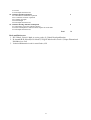
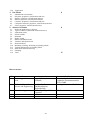
Annex –I: Tools & Equipments Required for First year _______________________________________ 341
Annex – II: Tools & Equipments Required for Second Year ____________________________________ 345
Expert Involved in Curriculum Revision, 2014 ______________________________________________ 351
3
Introduction:
The TSLC curriculum of Mechanical Engineering is designed to produce competent workforce equipped
with knowledge, skills and attitudes related to the field of mechanical engineering. This curriculum focuses
on basic mechanical skills and knowledge related to mechanical engineering to be used in related mechanical
workshop and industries.
Aims:
•
To produce competent lower level workforce in the field of mechanical engineering who will be able
to provide services in different related plants and industries.
•
To produce competent workforce who will get an opportunity to be self or wage employed in the
related national and international market.
Objectives:
After the completion of the training program the graduates will be able to:
•
Perform basic mechanical works carried out in mechanical workshops.
•
Perform basic computer applications
•
Perform mechanical drawings/drafting.
•
Design and perform sheet metal, steel and aluminum fabrications.
•
Operate lathe, milling and shaping machines.
•
Repair and maintain mechanical devices
Course Description:
This curriculum includes skills and knowledge related to the core subjects like applied English, mathematics,
and Nepali as well as disciplinary subjects like Bench work, Engineering drawing, lathe operation, material
science, sheet metal, welding technology, computer aided drafting, milling and shaping operation, structural
fabrication and repair and maintenance. This course also imparts with computer application and
entrepreneurship development.
This course also includes on the job training (OJT) so as to provide exposure of the world of work. The place
for OJT assignment will be related to mechanical workshops and industries.
Target group:
Class 10 passed individual
Group size:
Maximum 35 in a batch
Entry Requirements: a. 10th class pass.
b. Candidates will be selected on the basis of entrance examination as per CTEVT rule.
4
Medium of instruction: Nepali and/or English
Duration:
2 Years (3120 hrs + 5 months (800 hrs) = 3920 hrs
This course will be completed within 2 yrs (3120 hrs.) in formal setting. The 5 months OJT will be
compulsory after the final exam. The total hours for the course will be 3120+800 (OJT) = 3920 hrs.
Patterns of Attendance:
40 hrs. per week for 39 weeks per year and 90 % attendance is required.
Certificate Requirements: CTEVT will award the certificate in TSLC in Mechanical Engineering to the students who gain marks of
60% in practical test and 40% in knowledge test.
Evaluation Details:
a. Regular internal evaluation of the trainees has to be conducted by the related instructors to ensure the
proficiency over each task/skill in each subject.
b. Related technical knowledge of the tasks learnt by the trainees is to be evaluated through the written test.
Internal assessment will be conducted 3 times by the institute every year during the institutional training
period.
c. 80% marks is allotted to the practical work and 20 % is allotted to the related technical knowledge (trade
technology) in each subject.
d. The Controller of Examination of CTEVT will conduct final examination after completion of the course.
e. For each subject 60 % of the weight age will be allotted to the internal assessment and the rest of the 40
% to the final examination.
f.
The overall mark comes from adding the weight age score from the internal assessment and mark from
the assessment. Only the trainees who have passed the internal assessment can appear in the final exam.
g. A candidate who fails in the final exam can appear in the re-test scheduled by CTEVT.
h. After completion of the final examination On the Job (OJT) will be administered.
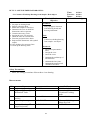
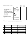
The course grading will be as follows:Overall Marks
Grading
a.
80Ü and above
Distinction
b.
75Ü to < 80Ü
First Division
c.
65Ü to <75 65Ü
Second Division
d.
Passed below 65Ü
Trainers' qualification:
Pass Division
•
BE in mechanical engineering or equivalent for instructor
•
Diploma in mechanical engineering for assistant instructor
•
TSLC in mechanical engineering for workshop assistant/teaching aid.
5
The objective of the on- the-job training
1. To gin knowledge and skills related to mechanical engineering by engaging the reel world of work.
2. To practice skills acquired from school in the real field.
3. To develop self-confidence in the skills acquired in the training institutions
4. To ensure the standard of the training to keep pace with the requirement of the employer.
The total marks for on-the-job training is distributed as:
1.
200 marks will be awarded by the supervisor of the user agency.
2.
200 marks will be awarded by the related training institute.
3.
100 marks will be awarded by CTEVT.
4.
OJT conduction and evaluation scheme will be as per the guidelines of CTEVT.
Basic Requirements
Office Equipment
There should be well-arranged equipment for training and office management.
a. Desk top Computer
c.
Scanner
Multi – media projector
d.
Laser color / mono printer
e.
Fax mail
f.
Photo Copy Machine (color / mono)
b.
Classroom Equipment
There should be well-arranged modern facilities for training and instruction management.
1. White Board
2. Soft Board
3. Multi media projector
4. Chair and desks.
5. Overhead projector
Library facilities
Essential furniture chair, table, racks, books, journal and periodicals.
6
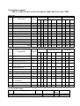
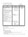
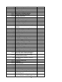
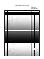
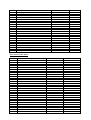
Curriculum structure
TSLC IN MECHANICAL ENGINEERING (PRE-SLC INTAKE), 2014
First year
S.
No.
1.
2.
3.
4.
5.
6.
7.
8.
9.
10.
11.
Class/ Week
Total Class/Year
T
P
Total
T
P
Total
78
78
78
0
0
0
0
39
0
0
117
390
0
0
0
429
78
117
156
0
156
234
0
1170
78
78
78
429
78
117
156
39
156
234
117
1560
50
50
50
0
0
0
0
25
0
0
75
250
0
0
0
275
50
75
100
0
100
150
0
750
50
50
50
275
50
75
100
25
100
150
75
1000
Course Title
Nature
T
P
Applied English
Applied Math - I
Applied Nepali
Bench Work
Computer Application
Engineering Drawing
Lathe Operation - I
Material Science - I
Sheet Metal Fabrication
Welding Technology - I
Workshop Technology - I
Total
T
T
T
P
P
P
P
T
P
P
T
2
2
2
0
0
0
0
1
0
0
3
10
0
0
0
11
2
3
4
0
4
6
0
30
Tot
al
2
2
2
11
2
3
4
1
4
6
3
40
Full Marks
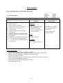
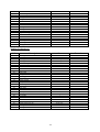
Second year
Class/Week
S.
No.
Course Title
Nature
1.
Applied Math - II
T
2
0
2.
Computer Aided Drafting
P
0
2
2
0
78
78
0
50
50
3.
Engineering Drawing - II
P
0
2
2
0
78
78
0
50
50
4.
T+P
1
1
2
30
48
78
20
30
50
5.
Entrepreneurship
Development
Lathe Operation -II
P
0
6
6
0
234
234
0
150
150
6.
Material Science - II
T
1
0
1
39
0
39
25
0
25
7.
Milling & Shaping Operation
P
0
8
8
0
312
312
0
200
200
8.
Repair & Maintenance
P
0
4
4
0
156
156
0
100
100
9.
10.
Structural Fabrication
Welding Technology – II
(Gas/TIG/MIG)
Workshop Technology - II
P
P
0
0
5
6
5
6
0
0
195
234
195
234
0
0
125
150
125
150
T
2
0
2
78
0
78
50
0
50
6
34
40
225
1335
1560
145
855
1000
Sub Total
P
Full Marks
Tot
al
2
11.
T
Total Class/Year
T
P
Total
T
P
Total
78
0
78
50
0
50
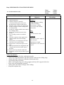
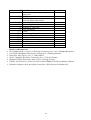
On-The-Job Training
S.No.
1
Subjects
Nature
On-the-job training
P
st
nd
Grand Total (1 year + 2 year +OJT)
Hours/Weeks
20
7
Total
Hours
800
3920
Full Marks
500
2500
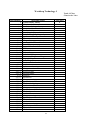
First Year
Subjects
1. Applied English
2. Applied Math - I
3. Applied Nepali
4. Bench Work
5. Computer Application
6. Engineering Drawing
7. Lathe Operation - I
8. Material Science - I
9. Sheet Metal Fabrication
10.
Welding Technology - I
11.
Workshop Technology - I
8
Applied English
Total 78 hrs
Class/week: 2 hrs
Unit/sub unit
1
1.1
2
2.1
3
3.1
4
4.1
5
5.1
5.2
5.3
6
7
7.1
8
8.1
9
9.1
10
10.1
11
11.1
12
12.1
12.2
12.2.1
12.2.2
12.2.3
12.2.4
13
13.1
13.2
14
14.1
15
16
16.1
16.2
16.3
16.4
17
18
18.1
19
19.1
20
20.1
21
21.1
21.2
21.3
22
Areas and Topics
Introduction
Noun, Verb, Adjective, and Adverb words.
Auxiliary and main verbs – uses
Word identification and practical use
Subject verb agreement
S+V+O
Drill mechanical words
Glossaries of mechanical
Tense and sentence structure
Simple, Present and Continuous
When + Simple Past + Past Continuous
When + Simple Past + Past perfect + Present Perfect + Present
Continuous.
Causative Verb
Punctuation
Rules and Examples
Affirmative / Negative Sentences
Concept + Practical Exercises
'Yes / No' question
Concept + Practical Exercises
'WH' question
Concept + Practical Exercises
'Tag' question
Concept + Practical Exercises
Letter writing
Parts of a letter
Types of letter
Social letter
Application
Complaint letter
Business letter
Memorandum writing
Definition important points
Skill in writing a memo
Report writing
Definition and methods of writing a report
Read, understand and use the technical terms
Practical job reports
Filling work
Drilling activities
G.I. Pipe cutting
Sawing
Read short technical publications
Read &Follow English language instruction
Techniques of writing instruction
Going to Future
Concept and Uses
Prepare a Speech
5 minute speech on birth control, Pollution, HIV Aids.
Voice – Active & Passive
Introduction
Kinds
Rules of changing active into passive voice
Reported speech
9
Time (hrs)
2
2
3
2
4+4
2
2
2
2
3
3
4
3
3
2
3
2
3
2
2
4
3
22.1
22.2
22.3
22.4
22.5
23
23.1
23.2
24
24.1
24.2
24.3
24.4
25
25.1
26
26.1
27
27.1
27.2
27.3
28
28.1
28.2
29
29.1
29.2
30
Introduction
Rules of changing direct into indirect speech
Statement
Imperative
Interrogative
Rearrangement of words
Techniques
Illustration and Practical exercises
Conditional sentences
Types
Structure
Examples
Practice Exercises
Relative clauses
Defining relative clause, sentences examples.
Joining sentences
Joining sentences with why, what, which, whom, and How.
Articles
Types
Rules of using it
Practice exercises
Preposition – place and time
Definition
Places and time preposition
Situational understanding
Definition
Types
Comprehension Practice
2
2
2
2
2
2
2
2
Total 78
10
k|of]ufTds g]kfnL
hDdf M &* 306f
sIff M @ 306f÷
306f÷xKtf
sf]if{ j0f{g M
k|fljlws lzIffnox¿df b'O jif]{ k|fljlws P;=Pn=;L= df tfnLd lng] k|lzIffyL{x¿sf nflu
g]kfnLsf Jofjxfl/s kIfdf cfjZos kg]{ eflifs ;Lksf] ljsf;sf nflu b]xfo adf]lhdsf]
Jofjxfl/s g]kfnL cWofkgsf nflu tof/ ul/Psf] 5 . o;df Jofjxfl/s g]kfnL Jofs/0f / ;fdfGo
/rgf tyf ;a–cf]e/l;o/sf] sfdsf] l;nl;nfdf cfjZos kg]{ Jofjxfl/s sfo{;+u ;DalGwt
ljifox¿ ;dfj]z ul/Psf 5g\ .
ljifo
kf7Ø306f
! Jofs/0f
•
•
•
•
•
•
•
•
•
•
kbljrf/ ;DaGwL 1fg -gfd, ;j{gfd, lqmof, ljz]if0f / cJoo_
zAb lgdf{0f k|lqmof -pk;u{, k|Too / ;df;_
jfSo lgdf{0f ;DaGwL 1fg
jfSosf lsl;d -;fdfGo, ld> / ;+o'Qm_
jfSo kl/jt{g ;DaGwL 1fg -cf1fy{s, OR5fy{s, k|Zgfy{s,
;Defjgfy{s cflb _
jfRo kl/jt{g ;DaGwL 1fg / k|of]u
d]sflgsn ;DaGwL kfl/eflifs zAbsf] 1fg / ltgsf] k|of]u $
ljk/Ltfy{s, kof{ojfrL, >'lt;d leGgfy{s zAbsf] 1fg / k|of]u
g]kfnL ;dfhdf k|rlnt d]sflgsn ljifo ;+u ;DalGwt zAb /
jfSk4ltsf] 1fg / k|of]u
$
#
@
#
#
$
$
*
@ efiff / cleJolQm
•
•
•
•
•
cg'R5]b n]vg k|lqmofsf] 1fg / k|of]u .
%
lgaGw n]vg k|lqmofsf] 1fg / k|of]u .
%
kq n]vg -3/fo;L kq, sfof{noLo kq, Jofkfl/s kq, Jofj;flos kq, ;+:d/0f (Memo)
kqsf] 1fg / k|of]u .
%
oflGqs -d]sflgsn_ ;DaGwL hgr]tgf lzIff -o;df oflGqs÷d]lzgsf] dxTj tyf To;af6
x'g;Sg] sdhf]/Lsf ljifodf ! k]hsf] n]v n]vfO{ To;af/] cfkm\gf] sIffdf af]Ng nufpg]
h:tf ;Lk lbg] / To;df cEof; u/fpg]_ .
$
d]sflgsn sfo{sf sf/0f x'g] jftfj/0f k|b'if0f / tL k|b'if0faf6 x'g] v/faL / d]sflgsn sfd
ubf{ Wofg lbg' kg]{ ljifodf hgr]tgf lzIff .
!
11
•
•
a"Fbf / ;f/f+z n]vgsf] 1fg / k|of]u
k|Zgsf] cfwf/df pQ/ n]vg k|lqmofsf] 1fg / cEof;
#
@
# k|ltj]bg n]vg
•
•
•
•
;fdfGo k|ZgfjnL tof/L ;DaGwL 1fg / k|of]u
#
sfo{ k|ltj]bg ;DaGwL 1fg / k|of]u
#
sfof{no Joj:yfkg ;DaGwL 1fg -Jofj;flos sfo{zfnfsf] :yfkgfsf nflu cfjZos of]hgf
tof/L ug]{, oflGqs ;DaGwL sfdsf nflu sfo{ of]hgfsf] tof/L ug]{, of]hgf ul/Psf]
sfo{qmdsf nflu jh]l6Ë ug]{_ ljifosf] 1fg / k|of]u
%
dfl;s tyf jflif{s k|ult k|ltj]bg ;DaGwL 1fg / k|of]u .
@
$ pBf]uaf6 pTkflbt ;fdu|Lsf] hfgsf/L÷1fg
hfgsf/L÷1fg
•
•
pBf]uaf6 pTkflbt j:t'sf] k|of]u cl3 To;sf] u'0f:t/ agf]6, k|of]u ljlw cflbsf] ljifodf
hfgsf/L ug{ ;fdu|L k|of]u klGhsf (Catalogue) cWoog / k|of]u ug]{ 1fg / cEof; . $
6]08/ tyf af]nkq ;DaGwL 1fg
@
12
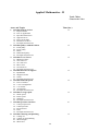
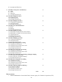
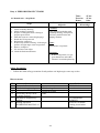
Applied Mathematics - I
Total: 78 hrs
Class/week: 2 hrs
Areas and Topics
Time (hrs.)
1. Calculate SI units / conversion factors
1.1. Basic Units
1.2. Derived SI units and relationship
1.3. Decimal, multiples and parts of units
1.4. Example and Exercises
2. Calculate other system of units(FPS system, CGS system, Metric system)
2.1. Conversion and Comparative table of previous technical units and SI units
2.2. Example and Exercises
3. Calculate fractions
3.1. Concept and Value of a fraction
3.2. Multiplication
3.3. Division
3.4. Addition
3.5. Subtraction
3.6. Example and Exercises
4. Calculate square root
4.1. Square number
4.2. Splitting up
4.3. Procedure
4.4. Example and Exercises
5. Calculate percentage
5.1. Conversion of the percentage into actual number
5.2. Conversion of the real number into percentage
5.3. Example and Exercises
6. Calculate conversion of length measurement
6.1. Metric System
6.2. SI System
6.3. Examples and Exercises
7. Calculate circumferences
7.1. Definition of circumference
7.2. Circumference
7.3. Sector
7.4. Polygons
7.5. Examples and Exercises
8. Calculate Pythagoras' Theorem
8.1. Terms used in Pythagoras' Theorem
8.2. Pythagoras formula
8.3. Summary
8.4. Examples and Exercises
9. Calculate by unitary method
9.1. Concept of Unitary method
9.2. Variance and types
9.3. Chain rule
9.4. Estimate time, money and number of worker for any job
9.5. Examples and Exercise
10. Calculate stretched lengths
10.1. Stretched length
10.2. Complete ring
10.3. Partial ring
10.4. Angular frames
10.5. Examples and Exercises
11. Calculate Trigonometric functions
13
4
2
4
2
2
2
4
4
4
2
4
12.
13.
14.
15.
16.
17.
18.
19.
20.
21.
11.1. Dependency
11.2. Side ratio
11.3. Relationships
11.4. Examples and Exercises
Calculate areas regular quadrilaterals
12.1. Square
12.2. Rhombus
12.3. Rectangle
12.4. Parallelogram
12.5. Examples and Exercises
Calculate Areas
13.1. Triangle
13.2. Trapezium
13.3. Circle
13.4. Sector
13.5. Circular ring
13.6. Examples and Exercises
Calculate Sheet metal requirements and wastage
14.1. Division
14.2. Wastage
14.3. Examples and Exercises
Calculate rivets
15.1. Calculate the length of rivet shank for riveting
15.2. Shearing force of rivet
15.3. Bearing pressure of rivet
15.4. Examples and Exercises
Calculate volume of right bodies
16.1. Concept of cube, prism and cylinder
16.2. Cube
16.3. Prism
16.4. Cylinder
16.5. Examples and Exercises
Calculate volume of pointed and truncated bodies
17.1. Cone / Pyramid
17.2. Truncated cone / Pyramid
17.3. Summary
17.4. Examples and Exercises
Calculate taper and inclination
18.1. Concept of taper and taper ratio
18.2. Taper ratio
18.3. Ratio of inclination
18.4. Setting angles
18.5. Taper length
18.6. Examples and Exercises
Calculate mass
19.1. Concept of mass and Density
19.2. Mass
19.3. Density
19.4. Examples and Exercises
Calculate mass and weight force
20.1. Concept of weight and force
20.2. Weight
20.3. Force
20.4. Examples and Exercises
Calculate stress
21.1. Concept of stress
21.2. Types of stress
21.3. Tensile strength
21.4. Factor of Safety
14
4
4
4
4
4
4
4
4
4
4
21.5. Load
21.6. Examples and Exercises
22. Calculate thermal expansion
22.1. Introduction of thermal expansion
22.2. Coefficient of linear expansion
22.3. Change in length
22.4. Final length
22.5. Examples and Exercises
23. Calculate heating and fuel consumption
23.1. Heat input or specific calorific capacity
23.2. Fuel consumption or amount of heat require for work done
23.3. Examples and Exercises
2
2
Total
78
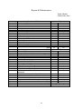
Book and References
1. H.P. Dahal ,United’s Math in action grade-10 ,United Nepal publication
2. R Awasthi,B.H. Subedi,B. B. Subedi ,UNIQUE Mathenatics book-9 ,Unique Educational
Publishers pvt. Ltd.
3. Technical Mathematics book for metal Trade ,GTZ
15
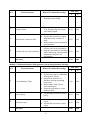
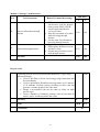
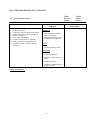
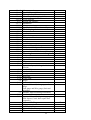
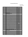
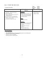
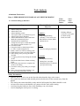
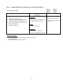
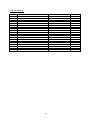
Bench Work
Total: 429 hrs
Class/week: 11 hrs
Duty/Task
Duty 1
Task 1
Task 2
Task 3
Task 4
Duty 2
Task 1
Task 2
Task 3
Duty 3
Task 1
Task 2
Task 3
Task 4
Task 5
Duty 4
Task 1
Task 2
Task 3
Task 4
Duty 5
Task 1
Task 2
Task 3
Task 4
Duty 6
Task 1
Task 2
Task 3
Task 4
Duty 7
Task 1
Task 2
Task 3
Task 4
Task 5
Task 6
Task 7
Duties and Tasks
Perform Filling
Demo
Time (hrs.)
Practical
Total
10
90
100
Familiarize with mechanical hand tools and
equipments
File flat surface (Plain)
File external radius
File internal profiles
2
4
6
4
2
2
50
20
16
54
22
18
Perform Marking/ Punching
4
21
25
Measure and Mark on the work piece
Stamp Letters and Numbers on metal plate
Punch: Dot and Center
2
1
1
4
12
5
6
13
6
Perform Cutting.
7
51
58
Saw metal by hand hack saw
Chisel flat surface.
Chisel grooved surface
Cut internal thread using hand taps(Tapping)
Cut external thread using threading dies(Dieing)
Drill a hole
Countersunk on hole
Counter bore on hole
Ream drilled hole using hand reamers
2
2
1
1
1
5
2
1
1
1
18
12
11
5
5
17
6
3
3
5
20
14
12
6
6
22
8
4
4
6
Perform Off Hand Grinding
4
10
14
Grind center punch.
Grind flat chisel
Grind marking scriber
Grind twist drills
1
1
1
1
3
3
2
2
4
4
3
3
Handle Measuring Instrument
5
25
30
Check square ness using back square
Check radius with radius gauge
Take angular measurements using bevel protector
Measure the dimensions using Vernier caliper.
1
1
1
2
5
5
5
10
6
6
6
12
Perform Drilling.
Perform Project Works
Manufacture a drill plate includes counterbore
and reamed holes.
Manufacture steel hammer of 500gm
Manufacture C – clamp
Manufacture back square of 120mm
Manufacture Center square
Manufacture Divider
Manufacture Hand Hacksaw Frame
Total
16
180
180
-
15
15
-
30
20
15
20
30
50
30
20
15
20
30
50
34
395
429
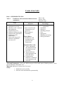
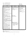
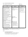
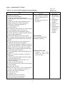
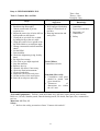
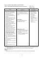
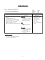
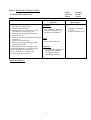
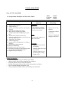
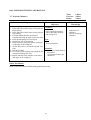
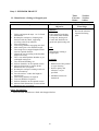
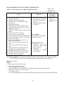
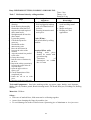
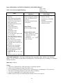
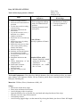
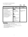
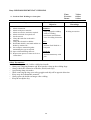
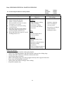
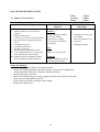
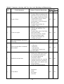
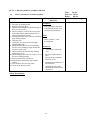
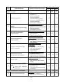
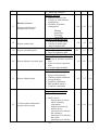
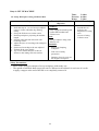
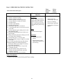
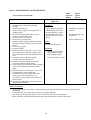
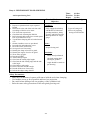
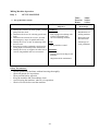
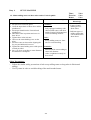
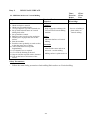
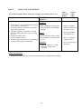
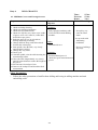
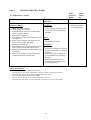
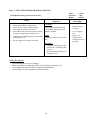
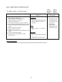
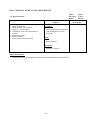
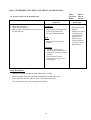
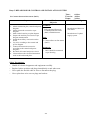
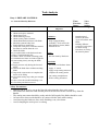
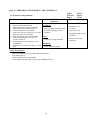
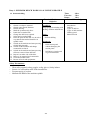
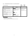
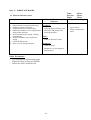
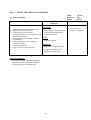
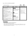
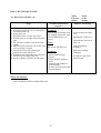
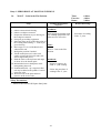
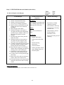
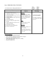
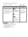
TASK ANALYSIS
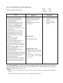
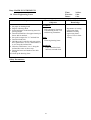
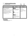
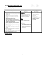
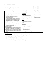
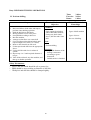
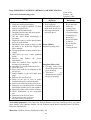
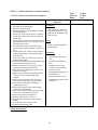
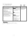
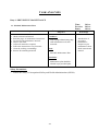
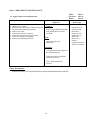
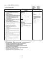
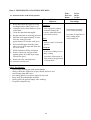
Duty: 1. PERFORM FILLING
Task: 1
Familiarize with mechanical hand tools and
equipments
Terminal performance
objectives
Obtain tools / materials and Condition (Given):
equipment as per list.
Introduce tools / materials
• Tool/ materials and
and equipment.
Equipments as per
Explain objectives.
given list.
Explain working principle
• Well equipped
Explain safety precaution.
workshop.
Explain care and
maintenance.
Tasks (What):
State work using tools /
• Familiarize with
material/ equipments.
mechanical tools,
Store the tools.
materials and
Equipments.
Steps
1.
2.
3.
4.
5.
6.
7.
8.
Time:-6 hrs
Theory:-2 hrs
Practical:-4 hrs
Related Technical
Knowledge
• Bench work tools and
equipments
• Definition
• Objective
• Working principle
• Uses
• Importance
• Handling and caring
• Safety precaution
Standard (How well):
• Tools, equipments
and material should
be identified as per
given list.
• Applied different
tools equipment and
materials safely
• Explained the
functions of different
tools equipment and
materials
Tools and Equipments:- Steel rule, Different types of file, Back square, Marking scriber, Center
punch, Hammers, Hand hack saw,
Materials: Mild steel, Carbon steel, Tool steel
Safety:• Handle the tools carefully.
• Store the tools and material systematically.
17
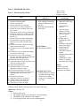
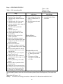
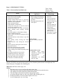
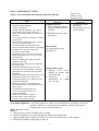
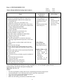
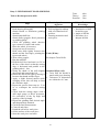
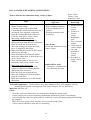
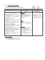
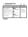
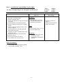
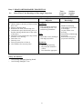
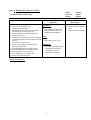
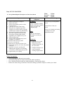
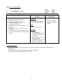
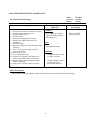
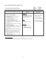
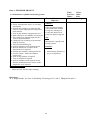
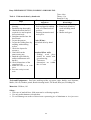
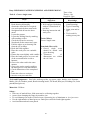
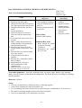
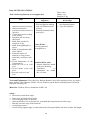
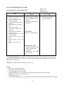
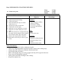
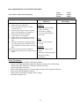
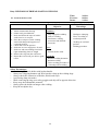
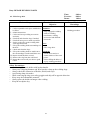
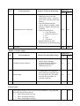
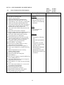
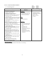
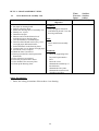
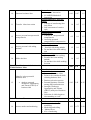
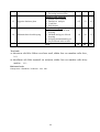
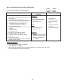
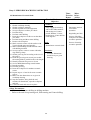
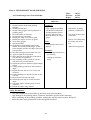
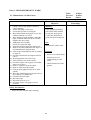
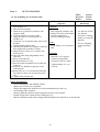
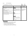
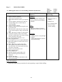
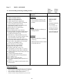
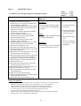
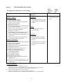
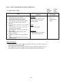
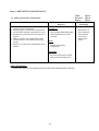
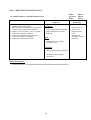
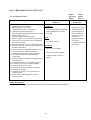
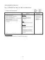
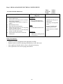
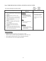
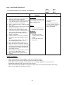
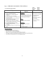
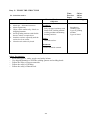
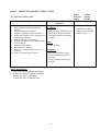
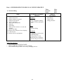
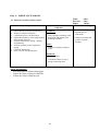
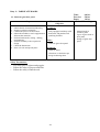
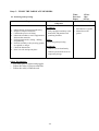
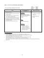
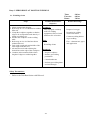
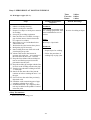
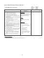
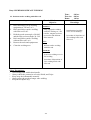
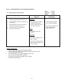
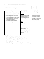
Duty: 1. PERFORM FILLING
Task: 2 File flat surface (Plain)
Steps
1.
2.
3.
4.
5.
6.
Obtain required drawing.
Read drawing thoroughly.
Obtain rough flat file.
Obtain material as per drawing.
Clean up the vice and working area.
Obtain steel rule, marking scriber and
back square.
7. Mark on the work piece as per drawing.
8. Clamp the work-piece centrally so that
the big flat surface can be file down on
Bench vice.
9. Hold the file by one hand with griping
the file handle so that the end of the
handle presses against the ball of the
thumb.
10. Press the file blade with the ball of the
thumb by the other hand.
11. Position the feet to safe distance during
filling.
12. Position the body to speedy and regular
movements of the body.
13. Put the file on top of the work-piece
pressing and pushing from one hand and
pressing only from other hand.
14. Return the file without pressure.
15. Apply the same motion to produces even
removal of filling surface.
16. Apply full length of file.
17. Check the flatness in cross and
diagonally with back square
18. Check measurement by steel rule
19. Repeat the same motion of filling across
and diagonally until produce even
surface.
20. De-burr the work piece.
21. Punch the roll no on work piece.
22. Oil the surface of the work piece.
23. Store the work piece and tools.
24. Clean the vice and work shop.
Terminal performance
objectives
Condition (Given):
• Well equipped workshop
with set of hand tools in
tool box.
• Drawing instruction and
work piece.
Tasks (What):
File flat surface (Plain)
Standard (How well):
• Filing work piece should
be match given drawing.
• Tolerances of filing
work piece is within the
±0.5 mm
Time:-50 hrs
Theory:-4 hr
Practical:-46 hrs
Related Technical
Knowledge
• Material of w/p
• Material of files and
introduction
• w/p clamping
devices
• care and safety
features of files,
bench vices, steel
rule, try square
• Type of file
• Proper way of
holding file while
filing
• Position of feet and
body while filing
• Measuring and
marking tools.
• State basis units of
length,
measurements and its
multiples
• Techniques of flat
filing i.e. straight,
cross and draw filing
Safety:
General, personal,
machine, tool and
equipment, workshop
Tools and Equipments:- Flat files, steel scale, Back square (try square),Marking scriber, Oil can,
Number punch, Bench cleaning brush, File brush, Dust pan
Materials: MS Flat, Oil
Safety:1. Follow safety rule.
2. The height of bench vice should be set before filing.
3. The handle of file should be fixed tightly.
4. Avoid using broken files on files without handle
18
5.
6.
7.
8.
Do not leave files remained above work pieces on bench vice
Don't touch the surface by naked fingers.
Full length of file should be used.
De-burr the edge of the material
19
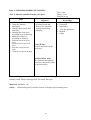
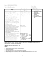
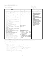
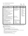
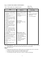
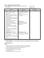
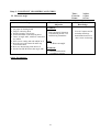
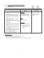
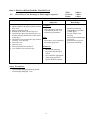
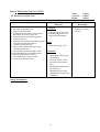
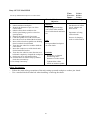
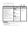
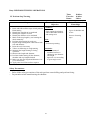
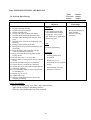
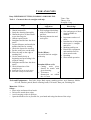
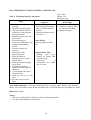
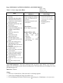
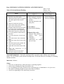
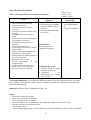
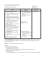
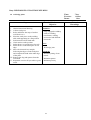
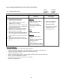
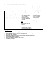
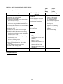
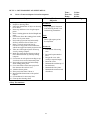
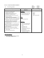
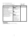
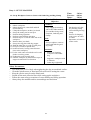
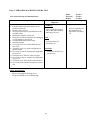
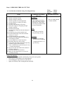
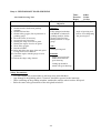
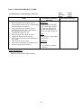
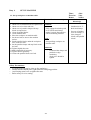
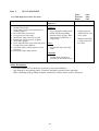
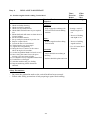
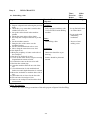
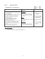
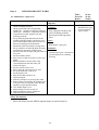
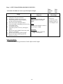
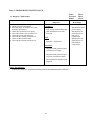
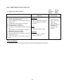
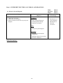
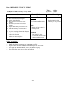
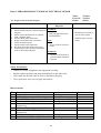
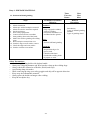
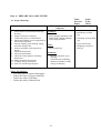
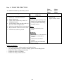
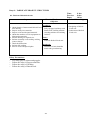
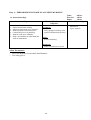
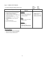
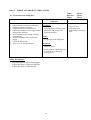
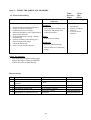
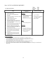
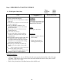
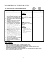
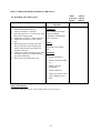
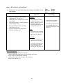
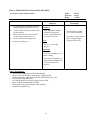
Duty: 1. PERFORM FILLING
Task: 3 File external radius
Steps
1. Obtain required drawing.
2. Read drawing thoroughly.
3. Obtain rough, medium and fine
flat files.
4. Obtain work-piece material.
5. Obtain a radius gauge of the
required size.
6. Obtain a centre punch and
hammer.
7. Obtain a steel rule.
8. Obtain a divider/compass.
9. Clean up the bench vice and work
area.
10. Mark the centre point of the
radius by divider.
11. Make the radius by compass.
12. Clamp the w/p projecting the
corner part which has to be made
radius.
13. File down to make flat surface
close to the marked radius line
using rough file.
14. Change medium flat file and start
filling in SEE SAW motion along
the curved line until all marked
line touches.
15. Check periodically with radius
gauge.
16. Remove the w/p and check the
measurement
17. File down further in see saw
motion with fine flat file until
required radius is obtained
18. Remove the w/p and check the
final measurement.
Terminal performance
objectives
Condition (Given):
• Well equipped workshop
with set of hand tools in
tool box.
• Drawing instruction and
work piece.
Time:-25 hrs
Theory:-2 hrs
Practical:-23 hrs
Related Technical
Knowledge
• Introduction of making
and layout using steel
rule, compass.
• Radius gauge.
• Method of filing radius
surface.
• State the feature of
compass.
• Radius filing procedure
Tasks (What):
File external radius.
Standard (How well):
• Filing work piece should
be match given drawing.
• Tolerances of filing
work piece is within the
±0.1 mm
19. Punch the roll no on work piece.
20. Oil the surface of the work piece.
21. Store the work piece and tools.
22. Clean the vice and work shop.
Tools and Equipments:- Flat files (Rough, medium, fine), radius gauge, Marking scriber, Center
punch, Number punch, Steel rule, Oil can, Number punch, Bench cleaning brush, File brush, Dust
pan
Materials: MS Square, Oil
Safety: - Refer the same safety precautions of the task "File flat surface.
20
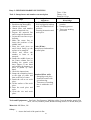
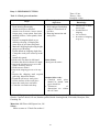
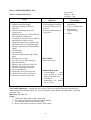
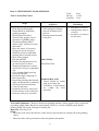
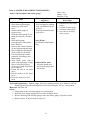
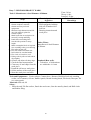
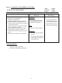
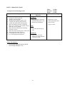
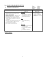
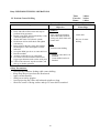
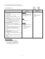
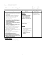
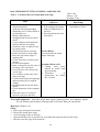
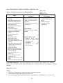
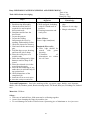
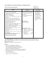
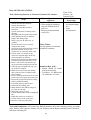
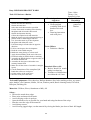
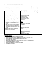
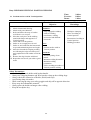
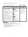
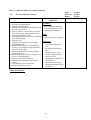
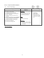
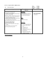
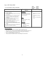
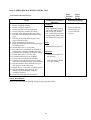
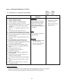
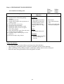
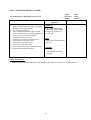
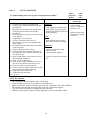
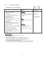
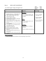
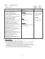
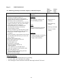
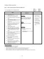
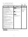
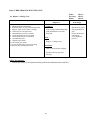
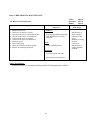
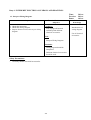
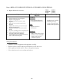
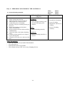
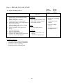
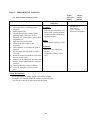
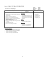
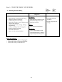
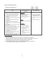
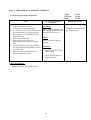
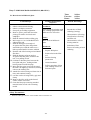
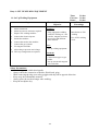
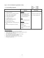
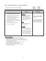
Duty: 1: PERFORM FILLING
Task: 4 File internal profile.
Steps
Terminal performance
objectives
Condition (Given):
• Well equipped workshop
with set of hand tools in
tool box.
• Drawing instruction and
work piece.
Time:-19 hrs
Theory:-1 hrs
Practical:-18 hrs
Related Technical
Knowledge
1. Obtain required drawing.
2. Read drawing thoroughly.
• Internal Radius filing
3. Obtain rough, medium and fine
procedure
flat files.
4. Obtain needle file if necessary
5. Obtain work-piece material.
6. Obtain a internal radius gauge of
the required size.
7. Obtain a centre punch and
hammer.
8. Obtain a steel rule.
9. Obtain a divider/compass.
10. Clean up the bench vice and
surrounding.
11. Mark the centre point of the
Tasks (What):
radius by divider.
File internal Profile.
12. Make the radius by compass.
13. Drill 5 mm small holes than that
require for profile size in chain
drill if necessary
14. De-burr the hole ends
15. Clamp the workpiece on bench
vice so that the holes can be filed
out
16. Take a small round file and file
out the chain holes (try to make
Standard (How well):
internal flat)
• Filing work piece should
17. Change the file as per required
be match given check
shape then file out
list.
18. Check out the sizes of the hole
• Tolerances of filing
with internal radius gauge or self
work piece is within the
made gauge
±0.5 mm
19. Check periodically with radius
gauge.
20. Remove the w/p and check the
measurement
21. Punch the roll no on work piece.
22. Oil the surface of the work piece.
23. Store the work piece and tools.
24. Clean the vice and work shop.
Tools and Equipments:- Flat files (Rough, medium, fine), radius gauge, Marking scriber, Center
punch, Number punch, Steel scale Oil can, Number punch, Bench cleaning brush, File brush, Dust
pan
Materials: MS Square, Oil
Safety: - Refer the same safety precautions of the task "File flat surface and Drill a hole".
21
Duty: 2: PERFORM MARKING/PUNCHING
Task 1: Measure and Mark on the work piece.
Steps
1. Obtain required drawing.
2. Study the drawing
thoroughly.
3. Obtain required tools and
materials.
4. Measure the work piece
according to given drawing.
5. Mark the work piece
according to drawing.
6. Punch the roll no on work
piece.
7. Oil the surface of the work
piece.
8. Store the work piece and
tools.
9. Clean the vice and work shop.
Terminal performance
objectives
Condition (Given):
• Working bench and
Bench vice with fully
equipped workshop.
• Drawing
Time:-6 hrs
Theory:-2 hrs
Practical:-4 hrs
Related Technical
Knowledge
Measuring and Marking
• Definition
• Importance
• Tool and equipment
• Method
• Safety
Tasks (What):
Measure and mark on the
work piece.
Standard (How well):
The measured and marked
work piece should be within
the given drawing.
Tools and Equipments:- Steel scale, Steel Protractor, Marking scriber, Center punch, Oil can,
Number punch, Bench cleaning brush, File brush, Dust pan
Materials: MS Sheet, Oil
Safety:- Hold marking tools carefully because of sharpen tip of marking tools.
22
Duty: 2: PERFORM MARKING/PUNCHING
Task 2: Stamp letters and numbers on metal plate
Terminal performance
objectives
1. Obtain the w/p drawing.
Condition (Given):
2. Read drawing thoroughly.
• Well equipped workshop
3. Obtain w/p material.
with set of hand tools in
4. Obtain letter and number
tool box.
punch of required size.
• Drawing instruction and
5. Prepare the material flat
work piece.
and in required dimensions.
6. Layout the base lines as per
drawing.
7. Make the centre line to
locate the position of the
middle letter.
8. Place the work piece on Tasks (What):
anvil block facing up the Stamp letters and numbers
surface to be stamped.
on metal plate.
9. Check and Select the
number or letter to be
stamped.
10. Stamp the middle letter on
the centre column line by
holding the punch with
three fingers of one hand
and striking the hammer on
head of punch by other
hand.
11. Check the impressions.
12. Stamp the remaining letters Standard (How well):
to the right of centre and • Stamping work piece
then to the left of centre.
should be match with
13. Punch the roll no on work
given drawing.
piece.
• Tolerances of marking
14. Oil the surface of the work
line is within the ±0.5
piece.
mm
15. Store the work piece and
tools.
16. Clean the vice and work
place.
Steps
Time:-13 hrs
Theory:-1 hr
Practical:-12 hrs
Related Technical
Knowledge
• Letter and number
punches.
• Stamping process.
• Three step stroking
procedure
Tools and Equipments:- Steel rule, Steel hammer, Marking scriber, Letter & number punch, Flat
anvil, Oil can, Number punch, Bench cleaning brush, File brush, Dust pan
Materials: MS Sheet, Oil
Safety:1. Assure the head of the punch in flat.
23
2. Avoid mushroom head punch.
3. Wipe off oily substance, if any from the face of the hammer.
4. Make sure that the face of the hammer strikes on punch head, use on fingers.
5. While punching remove bangles and wrist watches.
24
Duty: 2: PERFORM MARKING/PUNCHING
Task 3: Punch dot center on the object
Terminal performance
objectives
1. Obtain the w/p drawing.
Condition (Given):
2. Read drawing thoroughly.
• Well equipped workshop
3. Obtain the w/p material.
with set of hand tools in
4. Obtain steel rule, marking scriber,
tool box.
steel hammer, centre or dot
• Drawing instruction and
punch.
work piece.
5. Prepare the w/p material flat as
per required dimension.
6. Mark the symmetrical lines as per
drawing using steel rule and
marking scriber.
7. Place the w/p on flat anvil.
8. Hold the dot/centre punch by
three fingers of one hand and the
hammer on other hand.
9. Place the tip of the centre punch
at the cross of symmetrical lines.
Tasks (What):
10. Apply trial stroke.
Punch dot centre on the
11. Assess that the punch is at the
object.
correct centre.
12. Align if required.
13. Punch further stroke to get good
impression.
14. Take next cross line and punch
the centre.
Standard (How well):
15. Move center from self-ward while • Check trial stroke.
punching numerous dotted in
• Punching work piece
same line.
should be match with
16. Repeat the same steps for other
given drawing.
cross lines until finished.
• Tolerances of marking
17. Punch the roll no on work piece.
line is within the ±0.5
18. Oil the surface of the work piece.
mm
Steps
Time:-6 hrs
Theory:- 1 hrs
Practical:-5 hrs
Related Technical
Knowledge
• Introduction of punch
and its types
• Dot punch, its included
angle and its uses.
• Dots punch material.
• Centre punch, its
included angles and its
uses.
• Centre punches material.
19. Store the work piece and tools.
20. Clean the vice and work shop.
Tools and Equipments:- Steel rule, marking scriber, steel hammer, centre punch or dot punch,
anvil, Oil can, Number punch, Bench cleaning brush, File brush, Dust pan
Materials: MS Sheet, Oil
Safety:1. Assure the head of the punch is flat.
2. Avoid mushroom head punch.
3. Wiper off oily substance, if any, from the face of the hammer.
4. Look at the punch tip, not at the head while punching.
5. While punching remove bangles and wrist watches.
25
Duty: 3: PERFORM CUTTING.
Task :1 Saw metal by hand hack-saw
Terminal performance
objectives
Steps
1. Obtain the w/p drawing.
2. Read drawing thoroughly.
3. Obtain the w/p material.
4. Obtain required hand tools i.e.; steel rule,
marking scriber, dot punch, hammer and
hacksaw frame with blade).
5. Make symmetrical line.
6. Punch dotted on marked line.
7. Clamp the work piece so that the marked
line must be outside the vice.
8. Set the hand hack saw blade on hacksaw
frame making teeth pointing towards
forward.
9. Check the tightness of the blade in frame.
10. Take a small triangular file.
11. Mark a small Vee-notch by triangular file on
start point.
12. Hold the hacksaw frame firmly as per file
handling.
13. Start cutting slowly moving the blade
forward.
14. Apply pressure only during the forward
stroke.
15. Release pressure during the return stroke.
16. Repeat the strokes.
17. Check the cutting line to be straight.
18. Move slowly while finishing the cut.
19. Apply cutting on the blade frequently while
sawing.
20. Check the part that has been sawed.
21. Punch the roll no on work piece.
22. Oil the surface of the work piece.
23. Store the work piece and tools.
24. Clean the vice and work shop.
Condition (Given):
• Well equipped workshop
with set of hand tools in
tool box.
• Drawing instruction and
work piece.
Time:-20 hrs
Theory:-2 hrs
Practical:-18 hrs
Related Technical
Knowledge
•
•
•
•
•
•
•
Introduction of
hacksaw.
Types of hacksaw.
Parts of hack saw.
Hacksaw blades and
their types and
material.
Selecting blade for
different materials
and sections.
Holding different
sections of w/p for
hack sawing.
Procedure of sawing
the metal by hand.
Tasks (What):
Saw the metal by hand hack
saw.
Standard (How well):
•
•
Sawing work
piece
should be match with
given drawing.
Tolerances
of
dimensions are within
the ±0.5 mm
Tools and Equipments:- Hand Hacksaw frame, Hacksaw blade, steel rule, marking scriber, steel
hammer, flat anvil, dot punch/center punch, Oil can, Number punch, Bench cleaning brush, File
brush, Dust pan, Triangular file, Finishing file
Materials: MS Flat or MS Angle, Oil
Safety:1. Hold the job so as to cut on flat side rather than edge.
2. The teeth of the hacksaw blade should point towards the forwards direction.
3. The cutting movement should be steady and straight.
4. The full length of the blade should be engaged per stroke.
5. Avoid moving the blade too fast; slow down while finishing the cut.
6. Neither the blades too much neither tighten nor loose.
7. Avoid clamping the w/p over hang.
26
Duty: 3: PERFORM CUTTING.
Task :2 Chisel flat surface.
Terminal performance
objectives
Steps
1.
2.
3.
4.
Obtain the w/p and drawing.
Read drawing thoroughly.
Obtain work-piece material.
Obtain flat chisel, steel rule, height
gauge, marking scriber, center punch,
Steel hammer.
5. Prepare rectangular block as per
drawing referring / following the
same steps of previous task.
6. Mark the chipping depth using height
gauge as per drawing.
7. Punch dotted on chipping depth line.
8. Clamp the work-piece securely in the
vice.
9. Install chip guard.
10. Hold flat chisel in left hand.
11. Position the chisel at about 60°.angle
12. Hold the hammer at the end of the
handle for maximum leverage.
13. Strike on chisel head starting from
edge of the work-piece.
14. Stop chipping at the very close to end
of the surface.
15. Turn the work-piece to chip at the end
from the opposite direction.
16. Repeat the chipping until required
surface quality and dimension obtain.
17. Punch the roll no on work piece.
18. Oil the surface of the work piece.
19. Store the work piece and tools.
20. Clean the vice and work shop.
Condition (Given):
• Well equipped workshop
with set of hand tools in
tool box.
• Drawing instruction and
work piece.
Time:-14 hrs
Theory:2 hrs
Practical:-12 hrs
Related Technical
Knowledge
•
•
•
•
Introduction of chisel
and its types.
Fundamental of
chipping.
Use of chisels.
Procedure of chipping
flat
Tasks (What):
Chisel flat surface.
Standard (How well):
•
•
Chiseled work piece
should be match with
given drawing.
Tolerances
of
dimensions are within
the ±0.5 mm
Tools and Equipments:- Hand Hacksaw frame, Hacksaw blade, steel rule, marking scriber, steel
hammer, flat anvil, Chisels, dot/center punch, Oil can, Number punch, Bench cleaning brush, File
brush, Dust pan, Triangular file, Finishing file
Materials: MS Flat or MS Square bar, Oil
Safety:1.
2.
3.
4.
5.
While chipping remove bangles and wrist watches.
Wear safety goggles.
The chisel head must be free from mushroom formation.
While chipping, look at the cutting edge of the chisel and not at the head of the chisel.
Wipe off oily substances, if any from the face of the hammer.
27
Duty: 3: PERFORM CUTTING.
Task :3: Chisel grooved surface.
Terminal performance
objectives
Steps
1.
2.
3.
4.
Obtain drawing.
Read drawing thoroughly.
Obtain work-piece material.
Obtain Cross cut chisel, Concave chisel,
Height gauge, Center punch, Steel rule,
marking scriber, Center punch, Steel
hammer.
5. Prepare rectangular block as per
drawing referring / following the
same steps of previous filing task.
6. Mark the chipping depth using height
gauge as per drawing.
7. Punch dotted on chipping depth line.
8. Clamp the work-piece securely in the
vice.
9. Install chip guard.
10. Hold cross cut chisel in left hand.
11. Position the chisel at about 60°.angle
12. Repeat the chiseling process as for flat
Time:-12 hrs
Theory:-1 hrs
Practical:-11 hrs
Related Technical
Knowledge
Condition (Given):
•
• Well equipped workshop
with set of hand tools in
tool box.
• Drawing instruction and
work piece.
•
•
•
Introduction of chisel
and its types.
Fundamental of
chipping.
Use of chisels.
Procedure of chipping
on groove
.
Tasks (What):
Chisel grooved surface.
surface from Step 13 to 18.
13. Hold concave chisel.
14. Repeat the chipping process as for step
14.
15. Repeat the chipping until required
grooving dimension obtain.
Standard (How well):
16. Punch the roll no on work piece.
• Chiseled work piece
17. Oil the surface of the work piece.
should be match with
18. Store the work piece and tools.
given check list.
19. Clean the vice and work shop.
• Tolerances
of
dimensions are within
the ±0.5 mm
Tools and Equipments:- Steel rule, marking scriber, dot/center, steel hammer, flat anvil, Cross cut
Chisels, Concave chisel, Oil can, Number punch, Bench cleaning brush, File brush, Dust pan, files,
Finishing file
Materials: MS Flat or MS Square bar, Oil
Safety:Refer as same as "Chisel flat surfaces".
28
Duty: 3: PERFORM CUTTING.
Task :4: Cut internal thread using hand taps(Tapping)
Steps
1.
2.
3.
4.
Obtain w/s drawing.
Read drawing thoroughly.
Obtain pre-machined work material.
Obtain drill size and required tools for internal
threads.
5. Obtain sets of taps and tap handle/wrench.
6. Mark and punch on centre to drill hole.
7. Drill hole of required tap drill size.
8. Countersink the hole.
9. De-burr the hole.
10. Re-clamp the w/p on bench vice in horizontal
position slightly above the vice jaws.
11. Fix the first tap in the tap handle/wrench.
12. Position the tap (90° with horizontal surface)
in the countersinked hole.
13. Hold the tap handle closer to the centre.
14. Exert steady downward pressure and turn the
tap handle in clockwise direction to start the
thread.
15. Ensure the thread as well as check the tap
alignment removing the tap handle.
16. Check the tap alignment with Back Square to
ensure the tap being 90 º with the w/p surface.
17. Make corrections, if necessary by exerting
slightly more pressure downward in the side
having angle greater than 90º
18. Fit the tap handle without disturbing the tap
alignment.
19. Make 1-2 clockwise turn and re-check the
alignment.
20. Turn the tap handle lightly without exerting
any downward pressure.
21. Turn anticlockwise quarterly after every
clockwise full turn.
22. Apply cutting oil frequently.
23. Cut thread until the tap is fully inside the hole
being threaded.
24. Remove the first tap.
25. Repeat the steps (18) to (23) for intermediate
(Tap no 2) and bottoming tap (Tap no 3).
26. Remove the chips from thread.
27. Clean oil and chips.
28. Clean the vice.
29. Punch the roll no on work piece.
30. Oil the surface of the work piece.
31. Store the work piece and tools.
29
Terminal performance
objectives
Condition (Given):
• Well equipped workshop
with set of hand tools in
tool box.
• Drawing instruction and
work piece.
Time:-6 hrs
Theory:-1 hrs
Practical:-5 hrs
Related Technical
Knowledge
•
•
•
•
•
Tasks (What):
Cut internal thread using
hand taps (Tapping).
Standard (How well):
• Tapping work piece
should be match with
given drawing.
Introduction
thread and its
types
Introduction
of tap and
tapping
Types of tap
Thread
nomenclature
Selection of
drill bit for
required
tapping
Tools and Equipments:- Drill m/c, Sets of twist drills, Bench vice, Set of hand tap, Cutting oil
can, Countersink 60º and 90º, Centre punch, Steel hammer, Number punch, Bench cleaning brush,
File brush, Dust pan, files, tap handle, checking bolt
Materials: MS Flat, Oil
Safety:1. Use cutting fluid while cutting threads to avoid heat.
2. Avoid applying side pressure without giving turning motion to tap.
3. Tap alignment should be correct since starting of thread to avoid breaking of taps.
4. Tap handle should be chosen as per tap size.
5. Chips after cutting threads must be cleaned out from the hole and vice.
30
Duty: 3: PERFORM CUTTING.
Task:5: Cut external thread using threading dies (Dieing)
Terminal performance
objectives
Steps
1.
2.
3.
4.
5.
6.
7.
8.
9.
10.
11.
12.
13.
14.
15.
16.
17.
18.
19.
20.
21.
22.
23.
24.
25.
Obtain w/p drawing.
Read drawing thoroughly.
Obtain w/p material.
Obtain required hand tools: file, caliper,
threading die, die handle, check nut.
Mark square at the end face as per thread
diameter.
File roughly using the procedure of filing a
square block.
File round bar of black using the steps of
taste "File external radius".
Check the blank size with hole gauge.
Re-file until the blank diameter is obtained.
Chamfer 45º at the end of the blank.
Fix the die in die handle
Re-clamp the w/p on vice projecting the
blank upward above the vice in 90º with
the horizontal.
Place the leading side of the die on the
chamfer of the w/p
Ensure the die is fully open by tightening
the centre screw.
Hold the die handle close to the centre.
Apply pressure on die handle evenly and
turn clockwise to advance the die on the
bolt blank.
Ensure the thread starts by the time reverse
frequently at about every quarter turn.
Cut thread until the die is fully down the
length to be threaded.
Increase the depth of cut gradually by
adjusting the outer screw and repeat above
steps (16-19).
Check the thread with check nut.
Clear the die and the bench vice.
Clean oil and chips.
Punch the roll no on work piece.
Oil the surface of the work piece.
Store the work piece and tools.
Condition (Given):
• Well equipped workshop
with set of hand tools in
tool box.
• Drawing instruction and
work piece.
Time:-6 hrs
Theory:-1 hrs
Practical:-5 hrs
Related Technical
Knowledge
• Introduction of Dies
and Dieing.
• Required blank size for
external thread.
Tasks (What):
Cut external thread using
threading dies.
Standard (How well):
•
•
Dieing
work
piece
should be match with
given drawing.
Tolerances
of
dimensions are within
the ±0.5 mm
Tools and Equipments:- Set of files, Check nut, caliper, Set of threading dies, Die handle, oil can with
cutting oil, Bench vice, Centre punch, Steel hammer, Number punch, Bench
cleaning brush, file set, file brush, Dust pan
Materials: MS rod, Oil
Safety:-
1.
2.
3.
4.
Check screws on the die handle before starting.
Check the depth of cut too much depth can damage die and threads.
Apply cutting fluid frequently to reduce heat and wash out the chips avoid clogging.
Keep the die handle at right angle to the job.
31
Duty: 4: PERFORM DRILLING.
Time:-8 hrs
Theory:-2 hrs
Practical:-6 hrs
Related Technical
Knowledge
• Introduction of drill m/c.
• Types of drill m/c
• Parts of drill machine
• Twist drills and its
types.
• Parts of drill bit
• Cutting speed, feed and
RPM.
• RPM calculation
according to the drill
size and w/p material.
• Handling of drill
m/c(Operation and
changing of belt )
• Safety
Task:1: Drill a hole
Terminal performance
objectives
1. Obtain the w/s drawing.
Condition (Given):
2. Read drawing thoroughly.
• Well equipped workshop
3. Obtain pre-finished w/p material.
with set of hand tools in
4. Obtain drill bit as per the required
tool box.
size.
• Drawing instruction and
5. Mark layout line on the w/p.
work piece.
6. Punch the centre.
7. Clamp the w/p on m/c vice of m/c
table.
8. Clamp the drill bit on drill chuck by
drill chuck key.
9. Set the RPM as per the drill bit size
and the w/p material.
10. Start the machine.
11. Set the coolant housing pipe.
12. Give hand feed.
Tasks (What):
13. Apply the coolant on the rotating Drill a hole.
drill bit.
14. Reduce the feeding pressure at the
bottom to the end.
15. Make sure the drill passes through.
Standard (How well):
16. Stop the machine.
• Drilling work piece
17. Remove the w/p from m/c vice.
should be match with
18. De-burr the drilled hole.
given drawing.
19. Clean oil and chips.
• Tolerances
of
20. Punch the roll no on work piece.
dimensions are within
21. Oil the surface of the work piece.
the ±0.1 mm except drill
22. Store the work piece and tools.
hole
23. Clean the vice and work shop.
Tools and Equipments:- Drill m/c with drill chuck key and drill bits, centre punch, steel hammer,
Drill vice, Oil can, Number punch, Bench cleaning brush, File brush, Dust pan, files.
Steps
Materials: MS Flat, Oil, Coolant
Safety:1. Tighten the table lock to avoid dislocation of the w/p.
2. Use parallel block to prevent drilling on m/c vice or table.
3. Check the cutting edge of drill before drilling.
4. Mount the drill shank to its maximum length inside the drill chuck.
5. Check the drill centre alignment to avoid breading of drill.
6. Apply coolant fluently.
7. Use cleaning brush to clean out the chips.
32
Duty: 4: PERFORM DRILLING.
Task:2: Countersink a hole
Steps
1. Obtain workshop drawing.
2. Read drawing thoroughly.
3. Obtain previously drilled w/p
material.
4. Obtain countersink as per the
required size.
5. Mount the same size of twist drill on
drill spindle on drill chuck.
6. Clamp the w/p in drill vice or hold by
hand placing at the m/c table.
7. Align the centre of m/c spindle with
the drilled hole to cut uniform angle.
8. Change countersink on drill machine
chuck.
9. Set the RPM
10. Start machine.
11. Check the alignment giving feed by
hand.
12. Re-align if necessary.
13. Give feed as per depth required.
14. Stop the machine.
15. Remove the work piece from vice.
16. Chamfer (De-burr) if necessary.
17. Check the final measurement.
24. Clean oil and chips.
25. Punch the roll no on work piece.
26. Oil the surface of the work piece.
27. Store the work piece and tools.
Terminal performance
objectives
Condition (Given):
• Well equipped workshop
with set of hand tools in
tool box.
• Drawing instruction and
work piece.
Time:-4 hrs
Theory:-1 hrs
Practical:-3 hrs
Related Technical
Knowledge
• Introduction to
countersink.
• Types of countersink.
• Importance of
countersinking.
• Safety
Tasks (What):
Countersink a hole.
Standard (How well):
• Countersinked
work
piece should be match
with given check list.
• Tolerances
of
dimensions are within
the ±0.1 mm
Tools and Equipments:- countersink 60º and 90º, Drill m/c with drill chuck key and drill bits,
centre punch, steel hammer, Drill vice, Oil can, Number punch, Bench cleaning brush, File brush,
Dust pan, files.
Materials: MS Flat, Oil
Safety:1. Check the cutting edge of the countersink.
2. Use drift to remove taper shank from drill spindle.
3. Use cleaning brush to clear out the chips.
4. Refer to the safety precaution of taste "drill a hole"
33
Duty: 4: PERFORM DRILLING.
Task:3: Counter Bore on Hole
Terminal performance
objectives
1. Obtain workshop drawing.
Condition (Given):
2. Read drawing thoroughly.
• Well equipped workshop
3. Obtain countersink as per the
with set of hand tools in
required size.
tool box.
4. Mount the same size of twist drill on • Drawing instruction and
drill spindle on drill chuck.
work piece.
5. Clamp the w/p in drill vice or hold
by hand placing at the m/c table.
6. Align the centre of m/c spindle with
the drilled hole to cut uniform angle.
7. Change countersink on drill machine
chuck.
8. Set the RPM
9. Start machine.
10. Check the alignment giving feed by
hand.
11. Re-align if necessary.
12. Give feed as per depth required.
Tasks (What):
13. Stop the machine.
Counterbore on hole.
14. Remove the w/p
15. Chamfer (De-burr) if necessary.
16. Check the final measurement.
17. Clean oil and chips.
18. Punch the roll no on work piece.
Standard (How well):
19. Oil the surface of the work piece.
• Counterbore work piece
20. Store the work piece and tools.
should be match with
given check list.
• Tolerances
of
dimensions are within
the ±0.1 mm
Steps
Time:-4 hrs
Theory:-1 hrs
Practical:-3 hrs
Related Technical
Knowledge
• Introduction to
countebore.
• Types of countebore.
• Importance of
counterbore.
• Safety
Tools and Equipments:- Drill m/c with drill chuck key, drill bits, centre punch, steel hammer,
Drill vice, Oil can, Number punch, Bench cleaning brush, File brush, Dust pan, files, counter bore
tool set.
Materials: MS Flat, Oil
Safety:1. Refer to the safety precaution of taste "Counter sink on hole"
34
Duty: 4: PERFORM DRILLING.
Task:4: Ream drilled hole using hand reamers
Steps
Time:
5 hrs.
Theory:
1 hrs
Practical: 6 hrs
Terminal
Related Technical
performance
Knowledge
objectives
Condition (Given):
• Introduction of
• Well equipped
reamer.
workshop with set of • Determine the drill
hand tools in tool
size for reamer
box.
• Procedure of using
• Drawing instruction
hand reamer.
and work piece.
1. Obtain workshop drawing.
2. Obtain pre-machined work-piece material.
3. Obtain guide drills, drill size for reamer and
Countersink 90°.
4. Clamp the work-piece on machine vice.
5. Drill a hole referring the same steps of previous
task from guide hole to drill size for reamer hole.
6. Change countersink and RPM
7. Countersunk the hole just as chamfer.
8. Stop the machine.
9. Fix the work-piece in the bench vice.
10. Hold tap handle on square end.
11. Place the reamer vertically on drilled hole.
12. Align the reamer with Try square.
13. Re-align if necessary.
14. Turn the tap handle in a clockwise direction
applying a slight downward pressure at the same
time.
15. Apply pressure evenly at both ends of the tap
Tasks (What):
handle.
Ream Drilled Hole
16. Ream the hole through.
Using Hand Reamers.
17. Ensure that the taper lead length of the reamer
comes out well and clear from the bottom of the
work.
Standard (How well):
18. Remove the reamer with an upward pull until the
• Reaming
work
reamer clear the hole.
piece should be
19. Clean the hole.
match with given
20. Check the accuracy with the required cylindrical
drawing.
pins
• Tolerances
21. Check the final measurement.
according to the
22. Clean oil and chips.
basic hole system.
23. Punch the roll no on work piece.
24. Oil the surface of the work piece.
25. Store the work piece and tools.
Tools and Equipments:- countersink 60º and 90º, Drill m/c with drill chuck key and drill bits,
centre punch, steel hammer, Reamer,Countersink,Drill vice, Oil can, Number punch, Bench
cleaning brush, File brush, Dust pan, Finishing file
Materials: MS Flat, Oil
Safety:•
Turn the tap handles steadily and slowly, maintaining the downward pressure.
•
Avoid turning the reverse direction for it will scratch the reamed hole.
•
Use Vice covers to protect the finished surfaces.
•
Apply oil to get good surface finish.
•
Refer also the safety precautions of task Drill a hole.
35
Duty: 5: PERFORM OFF HAND GRINDING.
Time:
Theory:
Practical:
Task:1: Grind Center Punch.
Terminal performance
objectives
1. Obtain workshop drawing.
Condition (Given):
2. Read drawing thoroughly.
• Well equipped
3. Obtain Bench or Pedestrian grinding
workshop with set of
machine.
hand tools in tool box.
4. Obtain blunt center punch.
• Drawing instruction
5. Obtain Safety goggles, Bevel protractor or
and work piece.
grinding gauge.
6. Check the grinding wheel abrasive type,
trueness of wheel and cracks.
7. Dress the wheel, if necessary.
8. Check the tool-rest, set up if necessary.
9. Hold blunt center punch left hand side
pointing the tip towards wheel.
10. Wear safety goggles
11. Run the machine.
12. Touch the angular part of tip on face of
Tasks (What):
wheel, holding left hand side so that it can
be turn freely by right hand side.
Grind Center Punch.
13. Give feeding slightly. Rotating the punch.
14. Check the angle with gauge or Bevel
protractor.
15. Repeat the grinding until desired angle
Standard (How well):
and sharpened tip obtained.
• Center punch should
16. Check the final measurement.
be match with given
17. Clean oil and chips.
drawing.
18. Punch the roll no on work piece.
• Tolerances
of
19. Oil the surface of the work piece.
dimensions are within
20. Store the work piece and tools.
the limit provided.
Steps
4 hrs.
1.0 hrs
3 hrs
Related Technical
Knowledge
•
•
•
•
•
•
Introduction of
center punch
Uses of Center
punch.
Procedure of
grinding center
punch.
Introduction of
off- hand
grinding
Type of grinding
wheel
Material
Component of
grinding wheel
Tools and Equipments:- Bench or Pedestrian grinding machine, Safety goggles, Bevel protractor
or grinding gauge, Blunt centre punch, steel hammer, Oil can, Number punch, Bench cleaning
brush, Dust pan, Finishing file
Materials: Blunt center punch, Oil
Safety:•
Make sure the grinding wheel guards are in place.
•
Always wear safety goggles.
•
Avoid working on grinding wheels which are loaded or glazed.
•
It is dangerous to working cracked or improperly balanced wheels.
•
Adjust the tool-rest as close to the wheels as possible. The maximum recommended gap is
2mm.
•
Small jobs should be held with pliers or other suitable tools.
•
Never holds jobs with cotton waste or similar materials.
•
Use gloves while grinding heavy jobs.
•
Avoid grinding on the side of the grinding wheels.
36
Duty: 5: PERFORM OFF HAND GRINDING.
Time:
Theory:
Practical:
Task:2: Grind Flat Chisel.
Steps
1. Obtain workshop drawing.
2. Read drawing thoroughly.
3. Obtain Bench or Pedestrian
grinding machine.
4. Obtain blunt Flat chisel.
5. Obtain Safety goggles, Bevel
protractor or grinding gauge.
6. Check the grinding wheel
abrasive type, trueness of wheel
and cracks.
7. Dress the wheel, if necessary.
8. Set up tool-rest if necessary.
9. Hold Flat chisel by both hand
pointing the tip towards wheel.
10. Wear safety goggles
11. Run the machine.
12. Position the angular part of tip
up ward on face of wheel,
fronting left hand side so that it
can be move freely by right hand
side.
13. Give feeding slightly moving
across the full face.
14. Check the angle with gauge or
Bevel protractor.
15. Repeat the grinding until desired
angle and sharpened tip obtained.
16. Check the final measurement.
17. Clean oil and chips.
18. Punch the roll no on work piece.
19. Oil the surface of the work piece.
20. Store the work piece and tools.
Terminal performance
objectives
Condition (Given):
• Well equipped workshop
with set of hand tools in
tool box.
• Drawing instruction and
work piece.
4 hrs.
1.0 hrs
3 hrs
Related Technical
Knowledge
•
•
•
Introduction of Chisels
Distinguish the features
of chisels.
Procedure of re-sharpen
the flat chisel.
Tasks (What):
Grind Flat Chisel.
Standard (How well):
• Chisel should be match
with given check list.
• Tolerances of dimensions
are within the limit
provided.
Tools and Equipments:- Bench or Pedestrian grinding machine, Safety goggles, Bevel protractor
or grinding gauge, Blunt flat chisel, steel hammer, Drill vice, Oil can, Number punch, Bench
cleaning brush, File brush, Dust pan, Finishing file
Materials: Flat chisel, Oil
Safety:•
Move the work across the full face of the wheel to prevent uneven wearing off of the grinding
wheel.
•
Refer the same safety precautions of the task grind center punch.
37
Duty: 5: PERFORM OFF HAND GRINDING.
Time:
Theory:
Practical:
Task:3: Grind marking scriber.
Steps
1. Obtain workshop drawing.
2. Read drawing thoroughly.
3. Obtain Bench or Pedestrian
grinding machine.
4. Obtain blunt Marking Scriber.
5. Obtain Safety goggles, Bevel
protractor or grinding gauge.
6. Check the grinding wheel
abrasive type, trueness of wheel
and cracks.
7. Dress the wheel, if necessary.
8. Set up tool-rest if necessary.
9. Hold Marking Scriber by left
hand pointing the tip towards
wheel.
10. Wear safety goggles
11. Run the machine.
12. Position the angular part of tip
up ward on face of wheel,
fronting left hand side so that it
can be rotate freely by right hand
side.
13. Give feeding slightly, rotating
the Marking Scriber.
14. Check the angle with gauge or
Bevel protractor.
15. Repeat the grinding until desired
angle and sharpened tip obtained.
16. Check the final measurement.
17. Clean oil and chips.
18. Punch the roll no on work piece.
19. Oil the surface of the work piece.
20. Store the work piece and tools.
Terminal performance
objectives
Condition (Given):
• Well equipped workshop
with set of hand tools in
tool box.
• Drawing instruction and
work piece.
4 hrs.
1 hrs
3 hrs
Related Technical
Knowledge
•
•
Features of Marking
Scriber
Procedure of resharpen marking
scriber
Tasks (What):
Grind marking scriber.
Standard (How well):
• Marking scriber should be
match with given check
list.
• Tolerances of dimensions
are within the limit
provided.
Tools and Equipments:- Bench or Pedestrian grinding machine, Safety goggles, Bevel protractor
or grinding gauge, Blunt Marking Scriber, Oil can, Number punch, Bench cleaning brush, Dust pan
Materials: Blunt marking scriber, Oil
Safety:•
Move the work across the full face of the wheel to prevent uneven wearing off of the grinding
wheel.
•
Refer the same safety precautions of the task grind center punch.
38
Duty: 5: PERFORM OFF HAND GRINDING.
Time:
Theory:
Practical:
Task:4: Re-sharpen twist drills.
Terminal performance
objectives
1. Obtain workshop drawing.
Condition (Given):
2. Read drawing thoroughly.
• Well equipped workshop
3. Obtain Bench or Pedestrian grinding
with set of hand tools in
machine.
tool box.
4. Obtain blunt drill bits.
• Drawing instruction and
5. Obtain Safety goggles, Bevel protractor
work piece.
or grinding gauge.
6. Check the grinding wheel abrasive
type, trueness of wheel and cracks.
7. Dress the wheel, if necessary.
8. Set up tool-rest if necessary.
9. Hold twist drills lightly between the
thumb and the first finger, pointing the Tasks (What):
tip towards wheel.
10. Wear safety goggles
Re-sharpen Twist Drills.
11. Run the machine.
12. Hold the drill level and turn it to 59° to
the face of the wheel so that the cutting
edge is horizontal and parallel to the
grinding wheel - face.
13. Swing the shank of the drill slightly Standard (How well):
downward and towards the left.
• Twist drill bit should be
14. Rotate the drill to the right by turning it
match with given drawing.
between the thumb and the finger.
• Tolerances of dimensions
15. Apply a slight forward motion while
are within the ±0.5 mm
swinging down; this will help to form
the clearance angle.
16. Repeat the process from step no. 13 to
16 to re-sharpen the second cutting
edge.
17. Check both the cutting edges with a
drill angle gauge or Bevel protractor,
for correctness of the lip angle and
equality of the lip length.
18. Repeat the grinding until desired angle
and sharpened tip obtained.
19. Check the final measurement.
20. Clean oil and chips.
21. Punch the roll no on work piece.
22. Oil the surface of the work piece.
23. Store the work piece and tools.
Steps
39
6 hrs.
1 hrs
5 hrs
Related Technical
Knowledge
• Introduction of drill
bit and its types
• Angle of drill bit
• Procedure of resharpen drill bit
Tools and Equipments:- Bench or Pedestrian grinding machine, Safety goggles, Bevel protractor
or grinding gauge, Blunt twist drill bit, Oil can, Number punch, Bench cleaning brush, File brush,
Dust pan
Materials: Twist drills, Oil
Safety:•
Move the work across the full face of the wheel to prevent uneven wearing off of the grinding
wheel.
•
Refer the same safety precautions of the task grind center punch.
40
Duty: 6: HANDLE MEASURING INSTRUMENTS.
Task:1: Check square-ness using back square
Steps
1. Obtain work shop drawing.
2. Read drawing thoroughly.
3. Obtain pre-machined w/p
material.
4. Obtain a back square of
required size.
5. Hold the w/p in one hand
and place the stock of the
square against the vertical
surface.
6. Slide the stock down the
vertical surface until the
blade touches the flat
surface of work piece.
7. Position the work so that
the light falls on it from
behind.
8. Check whether any light
passes between the workpiece and the blade if not,
the surfaces of w/p are 90º
to each other.
9. If yes correct the surface by
re-filing.
10. Check other adjacent angles
as same as the first one.
11. Wipe the back square.
Terminal performance
objectives
Condition (Given):
• Well equipped workshop
with set of hand tools in
tool box.
• Drawing instruction and
work piece.
Time:-6 hrs
Theory:-1 hrs
Practical:-5 hrs
Related Technical
Knowledge
• Introduction of back
square.
• Features of back square.
• Checking back Square
before use.
• Care of back square.
Tasks (What):
Check square- ness using
back square.
Standard (How well):
• Adjacent sides must be
90º to each other i.e. no
light should pass
between the blade and
12. Clean any oil and chips from
the surface.
the work piece.
• Work piece should be
13. Punch the roll no on work
match with given
piece.
drawing.
14. Oil the surface of the work
piece.
15. Store the work piece and
tools.
Tools and Equipments:- Back square, Steel rule, marking scriber, steel hammer, Oil can, Number
punch, Bench cleaning brush, File brush, Dust pan, file set, center punch
Materials: MS Flat, Oil
Safety:• Ensure that blade and the stock of back square are not damaged and are 90º to each other.
• Clean the w/p and de-burr before checking with back square.
• Hold the stock firmly against the w/p while sliding it down.
• Avoid placing back square where there is chance of falling and damaging.
41
Duty: 6: HANDLE MEASURING INSTRUMENTS.
Task:2: Check radius with radius gauge.
Steps
1. Obtain drawing.
2. Read drawing thoroughly.
3. Obtain pre- filed workpiece.
4. Obtain radius gauge as
required size.
5. Hold the radius gauge in one
hand & work-piece in other
hand.
6. Held radius gauge
perpendicular to the radius
to be checked.
7. Observe the contact surfaces
of any light passing through.
8. Move along the filed length
of the radius for checking.
9. File and adjust the radius
gradually according to the
radius gauge
10. Wipe them clean with a
clean cloth and apply a light
film of oil before storing.
11. Clean any oil and chips from
the work piece.
12. Punch the roll no on work
piece.
13. Oil the surface of the work
piece.
14. Store the work piece and
tools.
Terminal performance
objectives
Condition (Given):
• Well equipped workshop
with set of hand tools in
tool box.
• Drawing instruction and
work piece.
Time:-6 hrs
Theory:-1 hrs
Practical:-5 hrs
Related Technical
Knowledge
•
•
•
•
Introduction of the radius
gauge.
Features of radius gauge.
Self made radius gauge.
Procedure of checking
radius surface.
Tasks (What):
Check Radius with Radius
Gauge.
Standard (How well):
• No light should pass
between the gauge and
the surface.
Tools and Equipments:- Radius gauge, Steel rule, marking scriber, steel hammer, Oil can,
Number punch, Bench cleaning brush, File brush, Dust pan, file set, center punch
Materials: MS Flat, Oil
Safety:• Ensure that surface of radius gauge are not damaged.
• Hold the stock firmly against the w/p while sliding it down.
• Before checking with a radius gauge ensure the radius gauge is perfectly clean.
• Remove burrs, if any from the work-piece.
42
Duty: 6: HANDLE MEASURING INSTRUMENTS.
Task:3: Take angular measurements using bevel protractor.
Steps
1. Obtain work shop drawing.
2. Read drawing thoroughly.
3. Obtain pre-machined workpiece material.
4. Obtain Bevel protractor.
5. Set the angle that has to be
measure.
6. Hold the work-piece in one
hand and place the bevel of
the protractor against the
adjacent surface.
7. Slide the bevel down the
vertical surface until the
protractor blade touches the
angular surface.
8. Position the work so that a
bright light, such as a
window or an electric light,
is behind the work-piece.
9. Look at between work-piece
and protractor to see if any
light shows between the
blade and the work-piece. If
no light can be seen, the
surfaces of the work-piece
are at required angle.
10. Wipe the Bevel protractor
clean and put it in its storing
place.
11. Clean any oil and chips from
the work piece.
12. Punch the roll no on work
piece.
13. Oil the surface of the work
piece.
14. Store the work piece and
tools.
Terminal performance
objectives
Condition (Given):
• Well equipped workshop with
set of hand tools in tool box.
• Drawing instruction and work
piece.
Time:-6 hrs
Theory:-1 hrs
Practical:-5 hrs
Related Technical
Knowledge
•
•
•
•
Tasks (What):
Take Angular Measurements
Using Bevel Protractor.
•
Introduction of
Bevel protractor.
Features of bevel
protractor.
Uses of Bevel
protractor.
Importance of
measuring angular
surface..
Procedure of taking
angular
measurements
Standard (How well):
• No light should pass between
the blade of protractor and
the surface.
• Work piece should be match
with given drawing.
Tools and Equipments:- Bevel protractor, Steel rule, marking scriber, steel hammer, Oil can,
Number punch, Bench cleaning brush, File brush, Dust pan, Finishing file
Materials: MS Flat, Oil
Safety:•
Refer same safety precautions of the task of "Check square-ness using back square".
43
Duty: 6: HANDLE MEASURING INSTRUMENTS.
Task:4: Measure the dimensions using Vernier Caliper.
Terminal performance
objectives
Obtain pre-machined work-piece material. Condition (Given):
Obtain Vernier caliper.
• Well equipped workshop
Clean the caliper with a clean cloth.
with set of hand tools in
Check that the caliper reads correctly by
tool box.
moving the jaws together, so that they
• Drawing instruction and
touch & checking that scale reads zero.
work piece.
Clean the work-piece, remove burrs.
Steps
1.
2.
3.
4.
5.
6. Measuring outside dimensions.
7. Set the outside measuring jaws to a
dimension larger than that to be measured.
8. Place the fixed jaw against the w/p.
9. Move the sliding jaw so that the work
piece is gripped by the caliper.
10. Make sure that the jaws are in full contact
and not just their tips.
11. Read the number of millimeters on the
main scale which show in front of the zero
of the vernier scale.
12. Then read the tenths of mm (0.1) or
twentieths (0.05) on the vernier scale.
13. Measuring inside dimensions.
14. Set the inside measuring jaws of the
caliper to a dimension smaller than the
dimension to be measured.
15. Place the fixed jaw against the w/p.
16. Move the sliding jaw so that the caliper
grips the work-piece.
17. Read the measurement as for the outside
dimension.
Time:-12 hrs
Theory:-2 hrs
Practical:-10 hrs
Related Technical
Knowledge
•
•
•
•
Tasks (What):
Measure the dimensions using •
Vernier Caliper.
•
•
Introduction of
Vernier
caliper.
Features of
Vernier
caliper.
Reading the
scale.
Uses of vernier
caliper.
Least count of
vernier caliper.
Care and
maintain of
Vernier
caliper.
Procedure of
Using Vernier
Caliper
Standard (How well):.
• Tolerances of dimensions
are within the ±0.02mm
Tools and Equipments:- Vernier caliper, Steel rule, marking scriber, steel hammer, Oil can,
Number punch, Bench cleaning brush, File brush, Dust pan, file set, drill bit set,
Materials: MS Flat, Oil
Safety:•
Clean the work-piece and remove any burrs before taking any measurement.
•
Vernier calipers are precision measuring instruments and must be cared for accordingly.
•
Avoid leaving the caliper in a place where it could fall, contact with sharp cutting tools and thus
get damaged.
•
Wipe the vernier caliper clean and place it in its correct storage place.
•
Vernier calipers should be used only for measuring.
44
Duty: 7: PERFORM PROJECT WORK.
Task:1: Manufacture a Drill plate includes Counter-bore &
Reamed hole.
Steps
1. Obtain workshop drawing
2. Obtain workpiece material
3. Obtain necessary tool and
equipments
4. Measure rough dimension and
file one side (marrow) plane for
reference plane
5. Based on marrow file out all six
surface maintaining dimensions
and right angle.
6. Mark layout line on workpiece
for necessary drilling.
7. Punch dots on marking lines
8. Checked the drill machine and
clamping vice.
9. Make a drill hole according to
the given drawing on punched
dots.
10. Counter bore on required holes.
11. Counter sunk on all holes as its
requirement.
12. Reamed the drilled hole as its
requirements.
13. Check the final measurement.
14. Clean any oil and chips from
the work piece.
15. Punch the roll no on work piece.
16. Oil the surface of the work
piece.
17. Store the work piece and tools.
Terminal performance
objectives
Condition (Given):
• Well equipped workshop
with set of hand tools in
tool box.
• Drawing instruction and
work piece.
Time:-15 hrs
Theory:-0 hrs
Practical:-15 hrs
Related Technical
Knowledge
Tasks (What):
Manufacture a Drill plate
includes Counter-bore &
Reamed hole.
Standard (How well):.
• Tolerances of dimensions
are within the ±0.1 mm
Tools and Equipments:- Vernier caliper, Counter-bore , Reamer, Drill bits Steel rule, marking
scriber, steel hammer, Oil can, Number punch, Bench cleaning brush, File brush, Dust pan, file
set, center punch
Materials: MS Flat, Oil
Safety:•
Tighten the table lock nut to prevent the setting from being disturbed.
•
Use parallel block to prevent being drill on drill vice or machine table.
•
Check the cutting edge of drill bit before drilling a hole.
•
Mount the drill shank as much as possible.
•
Be ensuring the drill center is as you wish.
•
Apply fluent coolant.
•
Use cleaning brush to clean out the chips.
45
Duty: 7: PERFORM PROJECT WORK.
Task:2: Manufacture a Steel Hammer of 500mm.
Steps
1. Obtain workshop drawing
2. Obtain workpiece material
3. Obtain necessary tool and
equipments
4. Measure rough dimension and file
one side (marrow) plane for
reference plane
5. Mark layout line on workpiece for
necessary sawing and filing
6. Punch dots on marking lines
7. Saw the side portion for steep
length
8. Make rectangular block of required
size according to the given drawing
9. File radius on pin side
10. File next radius on bottom side
11. Drill a hole for wooden handle
12. File a hole of circular to oval
13. Enlarge side by side on both side in
all periphery
14. Chamfer and deburr all sharp edges
Terminal performance
objectives
Condition (Given):
• Well equipped workshop
with set of hand tools in
tool box.
• Drawing instruction and
work piece.
Time:-30 hrs
Theory:-0 hrs
Practical:-30 hrs
Related Technical
Knowledge
Tasks (What):
Manufacture a Steel Hammer
of 500mm.
Standard (How well):.
• Tolerances of dimensions
15. Check the final measurement.
are within the ±0.1 mm
16. Clean any oil and chips from the
work piece.
17. Punch the roll no on work piece.
18. Oil the surface of the work piece.
19. Store the work piece and tools.
Tools and Equipments:- Vernier caliper, Counter-bore , Reamer, Drill bits Steel rule, marking
scriber, steel hammer, Oil can, Number punch, Bench cleaning brush, File brush, Dust pan, file
set, center punch
Materials: MS rod, Oil
Safety:•
Refer the task File flat surface, Punch dot and center, Saw the metal by hand, and Drill a hole
and Radius filing.
46
Duty: 7: PERFORM PROJECT WORK.
Task:3: Manufacture a C - Clamp.
Steps
1. Obtain workshop drawing
2. Obtain workpiece material
3. Check rough dimension and file
out one side (marrow) plane as a
reference plane
4. Mark a layout for necessary
dimension to saw
5. Punch dots on marking lines
6. Drill holes to get internal radius
R7mm
7. Drill chain holes to cut out
unnecessary metal
8. Remove stock material by
chiseling the webs
9. Maintain the thickness of 15mm
with correct flatness and
squareness in geometrical
tolerances
10. Drill a hole Ø8,5mm for M10
thread
11. Make diamond surface on the
drill surface
12. Make radius of R12 and R7.5 on
two corners as per given drawing
13. Chamfer and finish the
workpiece
14. Check final measurements
15. Chamfer and deburr all sharp
edges
16. Check the final measurement.
17. Clean any oil and chips from the
work piece.
18. Punch the roll no on work piece.
19. Oil the surface of the work piece.
20. Store the work piece and tools.
Terminal performance
objectives
Condition (Given):
• Well equipped workshop
with set of hand tools in
tool box.
• Drawing instruction and
work piece.
Time:-20 hrs
Theory:-0 hrs
Practical:-20 hrs
Related Technical
Knowledge
Tasks (What):
Manufacture a C - Clamp.
Standard (How well):.
• Tolerances of dimensions
are within the ±0.1 mm
Tools and Equipments:- Vernier caliper, drill bits, Steel rule, marking scriber, steel hammer, Oil
can, Number punch, Bench cleaning brush, File brush, Dust pan, file set, center punch, tap set,
tap handle, drill machine
Materials: MS Flat, Oil
Safety:•
Refer the task Drilling, Sawing, Thread cutting by using taps and Plain filing.
47
Duty: 7: PERFORM PROJECT WORK.
Task:4: Manufacture a Back Square of 120mm.
Steps
Position 1:
1. Obtain workshop drawing
2. Obtain workpiece material as per
required number
3. Obtain necessary tool and
equipment
4. Measure rough dimension and file
out side by side to prepare a square
block with geometrically 90°
5. Mark a layout line on workpiece
6. Punch dots on marking line
7. Saw the metals to cut out
unnecessary parts
8. File out the flat even surface
9. File out opposite flat even surface
10. Maintain the thickness required
and flat even surface
11. File out the width of blade with
geometrically 90°
12. Drill the holes on side as per given
drawing
13. Chamfer and deburr all sharp
edges
14. Perform internal thread using hand
taps
15. Check the final measurements
Position 2:
Terminal performance
objectives
Condition (Given):
• Well equipped workshop
with set of hand tools in
tool box.
• Drawing instruction and
work piece.
Time:-15 hrs
Theory:-0 hrs
Practical:-15 hrs
Related Technical
Knowledge
Tasks (What):
Manufacture a Back Square of
120mm.
Standard (How well):.
• Tolerances of dimensions
are within the ±0.1 mm
1. Refer and follow the step of Pos.
2.
3.
4.
5.
6.
7.
1 from 4 to 11
Mark the layout line for drilling
the holes
Punch center on drilling marks
Drill the holes as per required size
Counter sunk the holes with 60°
Chamfer and deburr all sharp
edges
Check the final measurements
Tools and Equipments:- Vernier caliper, drill bits, Steel rule, marking scriber, steel hammer, Oil
can, Number punch, Bench cleaning brush, File brush, Dust pan, file set, back square, drill
machine, drill vice
Materials: MS Flat, Oil
Safety:•
Refer the task File flat surface, Saw the metal by hand, Drill a hole, internal thread using hand
taps and Countersink the hole.
48
Duty: 7: PERFORM PROJECT WORK.
Task:5: Manufacture a Center Square.
Terminal performance
objectives
Position 1:
Condition (Given):
• Well equipped workshop
1. Obtain workshop drawing
with set of hand tools in
2. Obtain workpiece material as per
tool box.
required number
•
Drawing instruction and
3. Obtain necessary tool and equipment
work piece.
4. Measure rough dimension and file out
Steps
side by side to prepare a square block
with geometrically 90°
5. Mark a layout line on workpiece
6. Punch dots on marking line
7. Saw the metals to cut out unnecessary
parts
8. File out the flat even surface
9. File out opposite flat even surface
10. Maintain the thickness required and
flat even surface
11. File out the width of blade with
geometrically 90°
12. Drill the holes on side as per given
drawing
13. Chamfer and deburr all sharp edges
14. Perform internal thread using hand
taps
15. Check the final measurements
Position 2:
Time:-20 hrs
Theory:-0 hrs
Practical:-20 hrs
Related Technical
Knowledge
Tasks (What):
Manufacture a Center Square.
Standard (How well):.
• Tolerances of dimensions
are within the ±0.1 mm
1. Refer and follow the step of Pos. 1
from 4 to 11
2. Mark the layout line for drilling the
3.
4.
5.
6.
7.
holes
Punch center on drilling marks
Drill the holes as per required size
Counter sunk the holes with 60°
Chamfer and deburr all sharp edges
Check the final measurements
Assemble the both parts with
countersunk head screws.
Tools and Equipments:- Vernier caliper, drill bits Steel rule, marking scriber, steel hammer, Oil
can, Number punch, Bench cleaning brush, File brush, Dust pan, file set, drill machine, drill
vice, center punch
Materials: MS Flat, Oil
Safety:•
Refer the task File flat surface, Punch dot and center, Saw the metal by hand, and Drill a hole
and Radius filing.
49
Duty: 7: PERFORM PROJECT WORK.
Task:6: Manufacture a Divider.
Steps
Position 1:
1. Obtain workshop drawing
2. Obtain workpiece material
3. Obtain necessary tool and
equipments
4. Measure rough dimension and file
one side (marrow) plane for
reference plane
5. Based on marrow, file out all six
surface maintaining dimensions
and right angle.
6. Mark layout line on workpiece for
necessary sawing and filing
7. Saw the side portion for steep
length
8. Make rectangular block of required
size according to the given
drawing
9. Chamfer and deburr all sharp
edges
10. Check the final measurement
Position 2:
Terminal performance
objectives
Condition (Given):
• Well equipped workshop
with set of hand tools in
tool box.
• Drawing instruction and
work piece.
Time:-30 hrs
Theory:-0 hrs
Practical:-30 hrs
Related Technical
Knowledge
Tasks (What):
Manufacture a Divider.
Standard (How well):.
• Tolerances of dimensions
are within the ±0.1 mm
1. Refer and follow the step of Pos. 1
from 1 to 10
2. Mark the layout line for drilling
the holes
3. Punch center on drilling marks
Assemble the both parts with
countersunk head screws.
Tools and Equipments:- Vernier caliper, drill bits Steel rule, marking scriber, steel hammer, Oil
can, Number punch, Bench cleaning brush, File brush, Dust pan, file set, center punch, drill
machine, drill vice
Materials: MS rod, Oil
Safety:•
Refer the task File flat surface, Punch dot and center, Saw the metal by hand, and Drill a hole
and Radius filing.
50
Duty: 7: PERFORM PROJECT WORK.
Task:7: Manufacture a Hand Hacksaw Frame.
Steps
Position Frame:
1. Obtain workshop drawing
2. Obtain workpiece material
3. Obtain necessary tool and
equipments
4. Measure rough dimension and file
one side (marrow) plane for
reference plane
5. Mark layout line on workpiece for
necessary sawing and filing
6. Punch dots on marking lines
7. Saw the side portion for steep length
8. Make rectangular block of required
size according to the given drawing
9. File radius on pin side
10. File next radius on bottom side
11. Drill a hole for wooden handle
12. File a hole of circular to oval
13. Enlarge side by side on both side in
all periphery
14. Chamfer and deburr all sharp edges
15. Check the final measurement
Position :
Terminal performance
objectives
Condition (Given):
• Well equipped workshop
with set of hand tools in
tool box.
• Drawing instruction and
work piece.
Time:-50 hrs
Theory:-0 hrs
Practical:-50 hrs
Related Technical
Knowledge
Tasks (What):
Manufacture a Hand Hacksaw
Frame.
Standard (How well):.
• Tolerances of dimensions
are within the ±0.1 mm
16. Obtain workshop drawing
17. Obtain workpiece material
18. Obtain necessary tool and
equipments
19. Measure rough dimension and file
one side (marrow) plane for
reference plane
20. Mark layout line on workpiece for
necessary sawing and filing
21. Punch dots on marking lines
22. Saw the side portion for steep length
Assemble the welding parts.
Tools and Equipments:- Vernier caliper, drill bits Steel rule, marking scriber, steel hammer, Oil
can, Number punch, Bench cleaning brush, File brush, Dust pan, file set, center punch, drill
machine, welding rod, tap set, die set, handles (tap and die)
Materials: MS square, Oil
Safety:•
Refer the task File flat surface, Punch dot and center, Saw the metal by hand, and Drill a hole
and Radius filing.
51
BOOK AND REFERENCES
•
•
•
•
•
•
S. K. Hajra Chaudhary,Workshop Technology(Vol. 1),Media promoters
Henp Fort, Shop Theory (Vol. 1), Trade School
W.A.J. Chapman, Workshop Technology(Vol. 1), Elsevier Science
Heinrich Gerling, Elementary Metal Course Training Section I
ETHIO, Arbeitsstelle fur Unterricht und Technik,GERMAN Technical Institute, Holetta.
Heinrich Gerling,All about MACHINE TOOLS,New ,Wiley Eastern Ltd India,1965.
52
Computer Application
Total: 78 hrs
Class/week: 2 hrs
Course Description:
This course intends to impart the competencies required to prepare document, spreadsheets,
presentations slides and database management sheets by using different computer application
packages.
Module: 1 Maintain Computer System
S.N.
Task Statements
Related Technical Knowledge
1.
Install Computer Peripheral
2.
Install Operating System
3.
Install Application/Driver
Software
Time (hrs)
T
Introduction
Identify input devices
(keyboard, mouse, joystick, and
scanner), output devices
(monitor, printer/plotter, sound
card, and speaker), central
processing unit, memory unit,
0.50
and auxiliary storage devices
(hard disk, CD/DVD/Blue Ray,
Pen drive, memory card).
Explain different types of ports
(Parallel, Serial, USB, IEEE
1394 and Slots)
Explain the precaution to be
taken while installing computer
peripheral.
Explain operating system
including its role.
Describe different types of
operating systems (MS-DOS,
Windows, Unix, Linux)
Enlist the function of DOS
Commands (COPY, REN, DIR,
TYPE, CD, MD and BACKUP). 0.50
Explain precautions to be taken
while installing operating
system.
Make a list of tasks to be
performed before, during and
after installation of MS Window
operating system.
Differentiate application
software and driver software.
Describe the uses of antivirus
0.5
program.
Explain the procedure for
53
P
1.00
4.00
2.00
S.N.
Task Statements
Related Technical Knowledge
4.
5.
Time (hrs)
T
P
installing application/driver
software
Describe the features of Control
Panel
Uninstall Software/Application
1.00
Format External Mass Storage
0.50
Sub total
1.50
8.5
Module: 2 Prepare Documents using Word Processing Package
S.N.
Task Statements
Related Technical Knowledge
6.
Perform Typing Practice
7.
Setup Page in Word Processing.
8.
9.
10.
Explain the interface of Word
Processing including different
tools/menu.
Describe how to open, save
document and exit.
Explain the procedure to type
document in word processing
software
Demonstrate systematic way of
typing.
Explain different features and
attributes of “Page Setup” Box.
Explain how to setup margins,
orientation, size and columns.
Define Breaks, Line numbers
and Hyphenation.
Explain the procedure to setup
page.
Time (hrs)
T
0.50
2.00
0.25
1.00
Insert Object/Picture/Photo
Insert Header/Footer
P
1.00
Insert Table
Differentiate Header and Footer.
Explain the procedure to insert
0.25
different header and footer in
different pages.
Explain row and column.
State the procedure to insert
table
0.50
Describe table formatting
procedure (Border and Color).
Sub total
1.50
54
1.00
1.00
6.00
Module: 3 Prepare Spreadsheets using Spreadsheet Package
S.N.
Task Statements
Related Technical Knowledge
11.
12.
Create workbook.
Analyze data using basic
formula/function
13.
Create Chart/Graph
14.
15.
16.
Filter Data
Sort Data
Setup Page in Spreadsheet
Explain the concept and uses of
Spreadsheet.
Interpret Spreadsheet’s
Interface.
Differentiate among column,
row, cell, workbook, worksheet,
labels, values, dates and
formulas.
Interpret “Insert Function” Box.
Differentiate Relative and
Absolute Cell Reference
Explain the procedure to insert
formula/function
Explain differentiate types of
charts/Graph.
State the procedure to create
chart/graph.
Differentiate between filtering
and sorting.
Explain the purpose of filtering.
Interpret filtered data.
Explain the purpose of sorting.
Interpret sorted data.
Explain different features and
attributes of “Page Setup” Box.
Explain how to setup margins,
orientation, size and columns.
Explain the procedure to setup
page.
Sub total
Time (hrs)
T
P
0.50
2.00
0.50
1.00
025
1.00
0.25
1.00
0.25
1.00
0.25
1.00
2.00
7.00
Module: 4 Create Presentation using Presentation Package
S.N.
Task Statements
Related Technical Knowledge
17.
Prepare Master Slide
Time (hrs)
T
Interpret Presentation package
interface including tools/menu.
Differentiate among slides,
master slide, outline, notes page,
1.00
handout master, notes master
and slide sorter.
Explain the purpose of
preparing master slide.
Enlist the procedure to prepare
55
P
1.00
S.N.
Task Statements
Related Technical Knowledge
Time (hrs)
T
P
master slide including
formatting and editing.
18.
Prepare Slides
19.
Animate the content of slide.
20.
Perform On-screen Presentation
Explain the procedures to insert
Text, Pictures/Objects/ Sound
and Charts/Graphs.
Define animation.
Explain the procedure to apply
animation to the content of
slide.
Differentiate between transition
and animation.
Explain the procedure to
perform on-screen presentation.
State the precautions to be taken
while connecting computer with
Multimedia Projector for
presentation.
Sub total
0.50
2.00
0.50
1.00
0.50
2.00
2.50
6.00
Module: 5 Maintain Database Management System using Database Package.
S.N.
Task Statements
Related Technical Knowledge
2.00
Explain the procedure to create
query.
0.50
1.00
State the procedure to generate
report.
Explain the procedure to print
report.
0.50
1.00
2.00
4.00
23.
Create Query
Generate report
P
1.00
Create Database Table
22.
T
Define Database.
Explain the purpose of Database
Management System
Interpret the interface of
Database Package including
tools/menu.
Differentiate Table, Query,
Form and Report.
Enlist the procedure to create
database table.
21.
Time (hrs)
Sub total
56
Module: 6 Manage e-mail/internets.
S.N.
Task Statements
24.
Browse Information through
Internet
25.
Time (hrs)
Related Technical Knowledge
Send mail through internet.
Differentiate among web server,
web browser, web site, domain
name system (DNS), WWW,
search engine and internet
service provider.
State the precaution to be taken
while browsing through
internet.
List the steps for information
browsing through internet.
Explain the concept of e-mail.
Differentiate Web based e-mail
and POP e-mail.
Explain the procedure to send
mail through internet.
Sub total
T
P
0.50
1.00
0.50
1.00
1.00
2.00
Project works
26.
Following projects are to be prepared and submitted (e-copy) using
different packages.
• Create a Bio-Data in Word Processing giving Educational and
Personal Details.
• Create a Spreadsheet Worksheet entering marks of five subjects
of 20 students. Perform sorting according to their rank and
generate a suitable graph for the same data.
• Design a presentation with not less than 10 slides on trade
specific topic.
• Create a Database in Database package with not less than 20
entries. Query and then generate the report.
Sub total
0
34.00
34.00
Total
67.5
10.50
Grand total
78
57
Engineering Drawing - I
Total: 117 hrs
Class/week: 3 hrs
Unit/sub unit
Duties and Tasks
Time - hrs
Th.
Pr.
1
1
1
1
1
2
2
1
0.5
0.5
0.5
0.5
0.5
0.5
1.5
1.5
1.5
1.5
1.5
3.5
1
1
1
2
2
3
3
2
2
2
14
6
2
1
-
16
7
8
2
-
8
4
6
21
96
1 Handle Instruments
1.1
1.2
1.3
1.4
2
2.1
2.2
2.3
2.4
2.5
2.6
Set up paper in drawing board
Draw title box using T set and Set square or Mini draft
Draw representative lines
Write engineering letter.
Construct Geometrical Figures
Bisect Straight line / divide line
Bisect an angle
Draw circle using compass
Draw square/rectangle
Draw triangle using set-square & protractor
Construct ellipse
3 Draw in Scale
3.1
3.2
3.3
3.4
Represent the drawing in scale.
Represent the dimension in detail
Determine the tolerances
Draw the symbols
4 Draw Pictorial Projection
4.1
4.4
5
5.1
5.2
5.3
Draw isometric projection
Draw oblique projection
Draw Orthographic Projection
Draw three view in first angle projection
Draw three view in Third angle projection
Find and draw missing views.
6 Draw Sectional Drawing
6.1
6.2
6.3
Draw full section views
Draw half section views
Draw partials section views
sub Total
Total
58
117
TASK ANALYSIS
Duty: 1.HANDLE INSTRUMENTS
Time:
Exercise:
Demo:
1.1 Set up Paper in Drawing Board
Steps
1. Place the drawing board straightness to the
left side
2. Clean up the drawing board
3. Set up base paper over drawing board
4. Place drawing paper over the base paper
4. Set the T-set on the drawing board
5. Align drawing paper with T-set
6. Hold on drawing paper with drawing tape
Terminal Performance
Objective
Condition:
Fully equipped Classroom
with Drawing board, T-set
and drawing instrument.
Task:
Set up paper in drawing
board.
Standards:
•
•
The bottom edge of paper
should be parallel to the Tset drawing edge.
Hold the drawing paper
without stretch.
Safety Precautions :
•
•
Avoid using damaged drawing board.
Avoid using damaged T-set.
59
2.0 hrs.
1 hrs
1 hrs
Related Technical
Knowledge
-
-
Paper size for drawing
and designing work.
Drawing board material, sizes and
application.
Uses of T-set.
Overview of drafter/mini
drafter
Duty: 1. HANDLE INSTRUMENTS
1.2 Draw Title Box Using T Set and Set Square
Steps
1. Set up paper in drawing board
2. Mark a point at top remaindering margin
with scale by pencil
3. Attach the T-set on ebony working edge so
that a horizontal line can draw on the
marked point
4. Draw a line of full length.
5. Mark the point at both sides remaindering
margins
6. Place the Set square aligning the working
edge of T-set so that a vertical line can
draw on side marked point
7. Draw a line of full length
8. Repeat the same steps for next vertical line
9. Repeat the steps of top horizontal line for
bottom horizontal line
10.Erase the lines over-drawn on every corner
13.Decide the information column and rows
14.Decide the dimensions of column and rows
15.Draw respectively from the bottom.
16.Write titles of the column.
17.Give darkness of all drawn lines with HB
pencil
18.Clean up the drawing sheet.
Time:
Exercise:
Demo:
Terminal Performance
Objective
3 hrs.
2 hrs
1 hrs
Related Technical
Knowledge
Condition:
Fully equipped Classroom
with Drawing board, T-set,
Setsquare and drawing
instrument.
Task:
Prepare a drawing sheet
using T - set and Set square.
Standards:
•
All the columns and row
for drawing information’s
should be allocatd.
•
Title box should be within
given area.
•
Title block should be made
in standard format.
Safety Precautions :
• Avoid using damaged drawing board.
• Avoid using damaged instruments.
60
-
Set square and its uses
Drawing sheet Title Box.
Paper size
Layout the drawing sheet
Particulars of title blocks
Duty: 1. HANDLE INSTRUMENTS
Time:
Exercise:
Demo:
1.3. Draw Engineering Lines
Steps
1. Set paper in drawing board
2. Prepare a drawing sheet
3. Scaled and mark the drawing sheet into
spacing 10 mm leaving the margin in side
boarder
4. Attach the ebony working edge of T-set
5. Bring the working edge on the marked
point
6. Draw a continuous thick line
7. Move T-set to next marked point and draw
the line
8. Repeat the step 7 and draw the lines in full
of the drawing sheet
9. Write continuous thick line and dates in
information column
10.Change drawing paper
11.Repeat same steps till step 5
12.Draw invisible line
13.Repeat the step 7 and draw the lines in full
of the drawing sheet
Terminal Performance
Objective
Condition :
Fully equipped Classroom
with Drawing board, T-set
and drawing instrument.
Task :
Draw representative lines.
Standards:
Line thickness should be
according to international
standard.
•
Neatness and cleanliness is
maintained.
•
Safety Precautions :
•
Rotate the pencil while drawing the lines to maintain the same thickness.
61
3.0 hrs.
2 hrs
1 hrs
Related Technical
Knowledge
•
Introduction of drawing
Engineering lines
•
Types of Engineering
lines and its applications.
•
Introduction of Pencil
and its uses and types in
engineering drawing
Duty: HANDLE INSTRUMENTS
Time:
Exercise:
Demo:
1.4 Write Engineering Letter
Steps
Terminal Performance
Objective
Condition :
1. Set paper in drawing board
2. Prepare a drawing sheet
Fully equipped Classroom
3. Scaled and mark on the drawing sheet for
with Drawing board, T-set
spacing height
and drawing instrument
4. Draw horizontal lines for approximately 26
letters and 10 numbers
Task :
5. Set up the compass for 70 ° inclined line
6. Draw dividend lines
Write engineering letter.
7. Hold the pencil vertically and start writing
the Capital letters "A to Z" and numbers "1
to 10" along the inclined line
Standards:
8. Write the small letters "a to z" along the
•
Letter should be block,
inclined line same as above step
uniform, neat and clean.
9. Ensure the letters and numbers are dark
enough
10.Clean up the drawing sheet.
Safety Precautions :
62
2.0 hrs.
1 hrs
1 hrs
Related Technical
Knowledge
- Importance of writing
engineering letter.
- Method of writing
engineering letters.
- Types of case in letter
writing.
Duty: 2. CONSTRUCT GEOMETRICAL FIGURES
Time:
Exercise:
Demo:
2.1. Bisect Straight line / Divide line
Steps
Terminal Performance
Objective
Condition :
1. Set paper in drawing board
2. Prepare a drawing sheet
Fully equipped Classroom
3. Decide the length of Straight line to be
with Drawing board, T-set
bisect
and drawing instrument.
4. Scaled and mark on the drawing sheet
5. Draw straight line AB, with centre A and
Task :
radius greater than half AB, draw arcs on
both sides.
To Bisect Straight line
6. Draw arcs intersecting the each other at C
and D.
7. Draw a line joining C and D and cutting AB Standards:
at E.
•
Line should be according to
8. Obtain the line AB (AE=EB)
provided dimension,
9. Bisect CD at right angle.
uniform, neat and clear
edge.
Safety Precautions :
63
2.0 hrs.
1.5 hrs
0.5 hrs
Related Technical
Knowledge
-
Introduction of
Geometrical Elements
Uses of Compass in
workshop drawings.
Instruments that uses to
draw arcs in drawing.
Duty: 2. CONSTRUCT GEOMETRICAL FIGURES
Time:
Exercise:
Demo:
2.2 Bisect an angle
Steps
1.
2.
3.
4.
5.
Set paper in drawing board
Prepare a drawing sheet
Decide an angle to be bisect
Scaled and mark on the drawing sheet
Draw an angle ABC, with B as centre and
any radius
6. Draw an arc cutting AB at D and BC at E.
7. Draw the arcs with centers D and E any
convenient radius
8. Draw arcs intersecting each other at F.
9. Join the line BF.BF bisects the angle ABC.
Terminal Performance
Objective
2.0 hrs.
1.5 hrs
0.5 hrs
Related Technical
Knowledge
Condition :
Fully equipped Classroom
with Drawing board, T-set
and drawing instrument.
Task :
To Bisect an angle.
Standards:
•
Dimension should be
according to criteria.
Safety Precautions :
64
-
Uses of Compass and in
workshop drawings.
-
Instruments that uses to
draw circles in drawing.
Duty: 2. CONSTRUCT GEOMETRICAL FIGURES
Time:
Exercise:
Demo:
2.3 Draw Circle Using Compass
Steps
1.
2.
3.
4.
5.
6.
7.
8.
9.
Set paper in drawing board
Prepare a drawing sheet
Decide the diameter of circle to be draw
Scaled and mark on the drawing sheet
Draw cross line and center line in each and
every marked centers
Obtain a compass, set the radius length in
scale as the circle to be draw
Place a needle of compass on the center
Hold rotator of compass, rotate it in
clockwise direction compressing towards a
pencil
Ensure the circle drawn is dark enough
Terminal Performance
Objective
Related Technical
Knowledge
Condition :
Fully equipped Classroom
with Drawing board, T-set
and drawing instrument.
Task :
Draw circle using compass.
Standards:
•
Start and end point should
not seen.
•
All lines should be uniform.
•
Radius/dimeter should be in
given dimension.
Safety Precautions :
•
•
2.0 hrs.
1.5 hrs
0.5 hrs
Handle compass carefully.
Keep the compass in proper place.
65
-
Uses of Compass and
representative of circles
in workshop drawings.
-
Instruments that uses to
draw circles in drawing.
Duty: 2.CONSTRUCT GEOMETRICAL FIGURES
Time:
Exercise:
Demo:
2.4. Draw Square / Rectangle
Steps
Terminal Performance
Objective
2.0 hrs.
1.5 hrs
0.5 hrs
Related Technical
Knowledge
Condition :
1. Set paper in drawing board
- Measuring.
2. Prepare a drawing sheet
Fully equipped Classroom
3. Decide the dimension of square or rectangle
with Drawing board, T-set
- Drawing shapes.
to be draw
and drawing instrument.
- Instruments that uses to
4. Scaled and mark on the drawing sheet
draw square / rectangles in
5. Refer and follow the steps of drawing sheet
drawing
preparation for construction lines.
Task :
6. Erase the projection lines if drawn
7. Ensure the rectangle or square drawn is
Draw square / rectangle.
dark enough
8. Clean up the drawing sheet.
Standards:
•
Corner should meet
equally.
•
All lines should be uniform.
•
Opposite line should be
parrallel.
Safety Precautions :
•
•
Avoid using damaged drawing board.
Avoid using damaged T-set.
66
Duty: 2. CONSTRUCT GEOMETRICAL FIGURES
2.5. Draw Triangle Using T set, Set Square and Protractor
Steps
Terminal Performance
Objective
Time:
Exercise:
Demo:
2.0 hrs.
1.5 hrs
0.5 hrs
Related Technical
Knowledge
Condition :
1. Set paper in drawing board
2. Prepare a drawing sheet
Fully equipped Classroom
- Drawing geometrical
3. Decide the dimension of equilateral triangle
with Drawing board, T-set
shapes.
to be draw
and drawing instrument
- Taking a measurement of
4. Scaled and mark on the drawing sheet
angles and triangles.
5. Draw a bottom horizontal line as decided
length
Task :
6. Draw a vertical perpendicular line at the
center of the line
Draw triangle using T set, set
7. Set the protractor as decided angle and
square and protractor.
mark with pencil point
8. Align the set square with end point of line
and pencil point
Standards:
9. Repeat it for another side inclined line.
•
Dimension should be meet
10.Joint the corners
according to given.
11.Erase projection lines if draw it
•
Line thickness should be in
12.Give darkness for necessary lines
standard.
Safety Precautions :
•
•
Avoid using damaged drawing board.
Avoid using damaged T-set.
67
Duty: 2.CONSTRUCT GEOMETRICAL FIGURES
Time:
Exercise:
Demo:
2.6. Construct Ellipse
Steps
Terminal Performance
Objective
Condition :
1. Draw a rhombus that side is diameter of
circle in 30
Fully equipped Classroom
2. Draw a line from the obtuse corner to
with Drawing board, T-set
center point of both side (so that the drawn
and drawing instrument
line should made 90 ° to the rhombus
side)
3. Draw a line from other obtuse corner to
Task :
center point of side
4. Obtain compass and set the leg along with
Construct ellipse
obtuse corner to center point of both
opposite sides
5. Draw an arc
Standards:
6. Draw another arc with same compass set
up from opposite corner to center point of • Ormity of line thickness.
sides
•
Maintain the line joints.
7. Re-set the compass from cross point of
•
Maintain the neatness and
center line to both center point of sides
cleanliness.
8. Draw another arc
9. Draw another arc with same compass set
up from opposite crossed point of center
line to center point of sides
10. Erase the rhombus and center lines
11. Give darkness for drawn ellipse.
Safety Precautions :
•
•
•
Keep the compass in safe position to other people.
Do not drop the compass on the ground.
Do not over press on the needle leg of the compass while drawing an arc.
68
4.0 hrs.
3.5 hrs
0.5 hrs
Related Technical
Knowledge
- Drawing ellipse type
- Construct methods of
ellipse
DUTY 3: DRAW IN SCALE
3.1 Represent the Drawing in scale.
Steps
1.
2.
3.
4.
5.
6.
7.
8.
9.
10.
11.
Terminal Performance
Objective
Condition :
Set paper in drawing board
Prepare a drawing sheet
Fully equipped Classroom
Decide the drawing for proper scale.
with Drawing board, T-set
Calculate the drawing measurement.
and drawing instrument.
Scaled and mark on the drawing sheet
Refer and follow the steps of drawing
three view, isometric, or sectional view to Task :
draw the view as needed
Write the actual dimensions including
Represent the drawing in
tolerances if any)
scale.
Write the name of using scale in title bock.
Erase projection lines if draw it
Standards:
Give darkness for necessary lines
10. Clean up the drawing sheet
• Draw the views and
dimension representation
with given scale.
Safety Precautions :
•
•
Avoid using damaged drawing board.
Avoid using damaged T-set.
69
Time:
3.0 hrs.
Exercise: 2.0 hrs
Demo:
1.0 hrs
Related Knowledge
- Definition of scale
- General principles and
rules of scale.
- Types of scale
DUTY 3: DRAW IN SCALE
3.2. Represent the Dimension in Detail
Steps
Terminal Performance
Objective
Condition :
1. Set paper in drawing board
2. Prepare a drawing sheet
Fully equipped Classroom
3. Decide the drawing that has to be draw with
with Drawing board, T-set
dimension in detail
and drawing instrument.
4. Scaled and mark on the drawing sheet
5. Refer and follow the steps of drawing three
view, isometric, or sectional view to draw
Task :
the view as needed
6. Draw the dimension lines and arrow heads
Represent the dimension in
in all independent shape and sizes which
detail.
included in the object (it may required to
present in many views)
7. Write the dimensions including tolerances Standards:
if any
• Draw the views and
8. Erase projection lines if draw it
dimension representation
9. Give darkness for necessary lines
with given scale and
10.Clean up the drawing sheet
tolerance.
Safety Precautions :
•
•
Avoid using damaged drawing board.
Avoid using damaged T-set.
70
Time:
4.0 hrs.
Exercise: 3.0 hrs
Demo:
1.0 hrs
Related Knowledge
- Introduction of
Dimension and terms of
dimensions
- General principles and
rules in dimensioning.
- Method of execution
- Arrows (depth and length
of arrow head)
DUTY 3: DRAW IN SCALE
3.3 Be familier with limit, fits and tolerances
Steps
Terminal Performance
Objective
Time:
4.0 hrs.
Exercise: 3.0 hrs
Demo:
1.0 hrs
Related Knowledge
Condition :
•
•
•
Introduce tolerences.
Define limit, fits and tolerences.
Differenciate hole basis and shaft
basis.
• Calculate tolerences.
Brief tolerences.
Fully equipped drawing class
room.
Task :
Be familier with limits, fits
and tolerances.
Sample exercise referring the steps of
Dimension in detail.
Standards:
•
Tolerence should be
allocated according to the
nature of workpiece.
Safety Precautions :
71
Introduction.
Limit, fit & allowance.
Surface tolerance.
Geometrical tolerance.
DUTY 3: DRAW IN SCAL
3.4. Draw the Symbols.
Steps
1. Set paper in drawing board
2. Prepare a drawing sheet
3. Decide the drawing that has to be draw
which symbol
4. Scaled and mark on the drawing sheet
5. Erase the unnecessary lines in draw
6. Give darkness for necessary lines
17.Clean up the drawing sheet
Terminal Performance
Objective
Time:
4.0 hrs.
Exercise: 2.0 hrs
Demo:
2.0 hrs
Related Knowledge
Condition :
Fully equipped Classroom
with Drawing board, T-set
and drawing instrument
Task :
Draw the symbols.
Standards:
Symbol should be clear and
appropriate for the
representation.
•
Safety Precautions :
72
-
First angle and third
angle projection symbol.
Dimensioning symbols.
Welding symbols.
Surface symbols.
Machine element
symbols.
Duty: 4 DRAW PICTORIAL PROJECTION
4.1
Draw Isometric Projection
Steps
Terminal Performance
Objective
Condition :
1. Obtain sample or drawing of object to draw
isometric view
Fully equipped Classroom
2. Determine the position in which draw
with Drawing board, T-set
isometric view to be able to show all the
and drawing instrument.
details
3. Draw a horizontal base line
Task :
4. Mark a point on the base line
5. Draw projection lines in both direction of
Draw isometric projection.
30 angle from marked point
6. Draw a vertical line from the base point
7. Mark the divisional points towards width
Standards:
upto end point
8. Mark the divisional points towards length
•
Line thickness should be
upto end point
uniform.
9. Draw parallel vertical lines on all division
•
Maintained symmetry and
points
line joints.
10.Mark the divisional points on vertical line
upto total height
•
Angle of the view should
11.Draw the parallel lines with 30 angle on all
be in standard.
divisional points
12.Draw other lines to figure out on the layout
13.Erase projection lines
14.Give darkness for necessary lines.
Safety Precautions :
73
Time:
Exercise:
Demo:
16.0 hrs.
14.0 hrs
2.0 hrs
Related Technical
Knowledge
- A type of drawing
represents.
- Pictorial views.
- Trimetric and oblique
projections and their
applications.
Duty: 4. DRAW PICTORIAL PROJECTION
4.2
Time:
Exercise:
Demo:
8.0 hrs.
6.0 hrs
2.0 hrs
Draw Oblique Projection
Steps
Terminal Performance
Objective
Condition :
1. Obtain sample or drawing of object to draw
oblique view
Fully equipped Classroom
2. Determine the position in which draw
with Drawing board, T-set
oblique view to be able to show all the
and drawing instrument.
details
3. Draw a horizontal base line
Task :
4. Mark a point on the base line
5. Draw projection lines in one direction of
Draw oblique projection.
180 angle and other direction is 30 or 45 or
60 angle from marked point
6. Draw a vertical line from the base point
Standards:
7. Mark the divisional points towards width
up to end point
•
Line should be uniform and
8. Mark the divisional points towards length
joint should be crossed.
up to end point
•
Neatness and cleanliness is
9. Draw parallel vertical lines on all division
maintained.
points
10.Mark the divisional points on vertical line
up to total height
11.Draw other lines to figure out on the layout
12.Erase projection lines
13.Give darkness for necessary lines.
Safety Precautions :
74
Related Technical
Knowledge
- A type of drawing
represents.
- Pictorial views.
- Oblique projections and
their applications.
- Concept of trimetric
projection.
Duty: 5. DRAW ORTHOGRAPHIC PROJECTION
5.1
Draw Three View Drawings in First Angle Projection
Steps
Terminal Performance
Objective
Condition :
1. Obtain sample or drawing of object to draw
three view
Fully equipped Classroom
2. Prepare a drawing sheet
with Drawing board, T-set
3. Determine the front, side and top view
and drawing instrument.
4. Calculate the space from drawing area. (so
that the drawing should come in the center
Task :
of the sheet)
5. Draw front view referring the steps of draw
Draw three views drawing in
isometric view drawing.
first angle projection.
6. Draw side view
7. Draw top view
8. Erase projection lines if draw it
Standards:
9. Give darkness for necessary lines
•
Maintained symmetry.
•
Projected line should be
visible.
•
Line should be approprite.
Safety Precautions :
•
•
Avoid using damaged drawing board.
Avoid using damaged T-set.
75
Time:
Exercise:
Demo:
18.0 hrs.
16.0 hrs
2.0 hrs
Related Technical
Knowledge
- Method of obtaining
orthographic projections
in first angle.
- Layout of three view
drawing.
- Introduction of third angle
projection.
- Introduction of types of
projection in drawing.
-
Duty: 5. DRAW ORTHOGRAPHIC PROJECTION
5.2
Draw Three View Drawings in Third Angle Projection
Steps
Terminal Performance
Objective
Condition :
1. Obtain sample or drawing of object to draw
three view
Fully equipped Classroom
2. Prepare a drawing sheet
with Drawing board, T-set
3. Determine the front, side and top view
and drawing instrument.
4. Calculate the space from drawing area. (so
that the drawing should come in the center
Task :
of the sheet)
5. Draw front view referring the steps of draw
Draw three views drawing in
isometric view drawing.
third angle projection.
6. Draw side view
7. Draw top view
8. Erase projection lines if draw it
Standards:
9. Give darkness for necessary lines
•
Maintained symmetry.
•
Projection line should be
visible.
•
Line should be appropriate.
•
Third angle projection
symbol should be placed.
Safety Precautions :
•
•
Avoid using damaged drawing board.
Avoid using damaged T-set.
76
Time:
Exercise:
Demo:
8.0 hrs.
7.0 hrs
1.0 hrs
Related Technical
Knowledge
- Method of obtaining
orthographic projections
in third angle.
- Layout of three view
drawing.
- Introduction of third angle
projection.
- Introduction of types of
projection in drawing.
-
Duty: DRAW ORTHOGRAPHIC PROJECTION
5.3
Time:
Exercise:
Demo:
Find and Draw Missing Views
Steps
Terminal Performance
Objective
Condition :
Obtain missing view drawing of object
Prepare a drawing sheet
Fully equipped Classroom
Identify the missing front, side or top view
with Drawing board, T-set
Draw it in rough paper
and drawing instrument.
Check the find out view with instructor
Calculate the space from drawing area. (so
that the drawing should come in the center Task :
of the sheet)
7. Draw all 3 views referring the steps of draw
Find and draw missing
3 view drawing in first angle projection
views.
8. Erase projection lines if draw it
9. Give darkness for necessary lines
Standards:
•
All the line of missing view
should be drawn
•
Projection line should be
visible.
•
Maintained symmetry.
1.
2.
3.
4.
5.
6.
Safety Precautions :
77
8 .0 hrs.
8.0 hrs
0.0 hrs
Related Technical
Knowledge
•
Process of finding
missing view through
projection line and given
drawing.
Duty: 6. DRAW SECTIONAL VIEWS
Time:
Exercise:
Demo:
6.1 Draw Full Section Views
Steps
Terminal Performance
Objective
Condition :
1. Set paper in drawing board
2. Prepare a drawing sheet
Fully equipped Classroom
3. Determine the projection view in which
with Drawing board, T-set
maximum sizes can be figure out
and drawing instrument.
4. Scaled and mark on the drawing sheet
5. Construct the view
6. Draw the sectional line based on center line Task :
and name it
7. Construct a sectional view
Draw full section views.
8. Draw visible outlines and edges with
continuous thick line
9. Draw hidden outlines and edges if any
Standards:
10.Draw hatching lines on cutting surface
•
Line thickness and angle of
11.Erase projection lines if draw it
hatching line should be
12.Give darkness for necessary lines
according to criteria.
13.Clean up the drawing sheet.
•
Maintained symmetry.
Safety Precautions :
78
10.0 hrs.
8.0 hrs
2.0 hrs
Related Technical
Knowledge
-
Importance of drawing
in section
Types of sectional views
Duty: 6. DRAW SECTIONAL VIEWS
Time:
Exercise:
Demo:
6.2 Draw Half Section Views
Steps
Terminal Performance
Objective
Condition :
1. Set paper in drawing board
2. Prepare a drawing sheet
Fully equipped Classroom
3. Determine the projection view in which
with Drawing board, T-set
maximum sizes can be figure out
and drawing instrument.
4. Scaled and mark on the drawing sheet
5. Construct the view
6. Draw the sectional line as per drawing and Task :
sectional represent based on center line and
Draw half section views.
name it
7. Construct a sectional view
Standards:
8. Draw visible outlines and edges with
continuous thick line
•
Line thickness and angle of
9. Draw hidden outlines and edges if any
hatching line should be
10.Draw hatching lines on cutting surface
according to criteria.
11.Erase projection lines if draw it
•
Maintained symmetry.
12.Give darkness for necessary lines
13.Clean up the drawing sheet.
Safety Precautions :
79
4.0 hrs.
4.0 hrs
0.0 hrs
Related Technical
Knowledge
•
•
Introduction of sectional
views.
Types of section drawing
Duty: 6. DRAW SECTIONAL VIEWS
Time:
Exercise:
Demo:
6.3 Draw Part Section Views
Steps
1. Set paper in drawing board
2. Prepare a drawing sheet
3. Determine the projection view in which
maximum sizes can be figure out
4. Scaled and mark on the drawing sheet
5. Construct the view
6. Draw the sectional line as per drawing and
sectional represent and name it
7. Construct a sectional view
8. Draw visible outlines and edges with
continuous thick line
9. Draw hidden outlines and edges if any
10.Draw hatching lines on cutting surface
11.Erase projection lines if draw it
12.Give darkness for necessary lines
13.Clean up the drawing sheet.
Terminal Performance
Objective
Condition :
Fully equipped Classroom
with Drawing board, T-set
and drawing instrument.
Task :
Draw part section views.
Standards:
•
•
•
•
•
•
Maintain the line spacing
for hatching.
Draw the section views.
Projected representative
lines.
Maintain the uniformity of
line thickness.
Maintain the line joints.
Maintain the neatness and
cleanliness
Safety Precautions :
80
6.0 hrs.
6.0 hrs
0.0 hrs
Related Technical
Knowledge
•
Importance of part
section.
BIBLIOGRAPHY
SN
1.
2.
Name
Engineering Drawing
Engineering Drawing for
Mechanical Trade
3.
Elements of Mechanical
Drafting
Engineering Drawing
4.
5.
Machine Drawing (1st
Angle Projection)
Author
P S Gill,
Samual Yaslov
N.D. BHATT
Er.R.K.DHAWAN
6.
81
Publication
S K Kataria & Sons
Instructional Material for
Vocational Training,
India
Delmar Publishers
Charotar Publishing
House Pvt. Ltd.
S.CHAND
Lathe Operation- I
Total: 156 hrs
Class/week: 4 hrs
Unit/sub unit
Duties and Tasks
Time (hrs.)
Demo
Practical
Set up round work piece on three jaw chuck
2
-
Set up Round/Square Workpiece on Four Jaw Chuck
3
2
-
2
2
-
1
1
1
2
2
2
2
2
2
4
2
4
13
14
7
4
14
6
-
10
16
22
14
1 Set Up Machine
1.1
1.2
1.3
1.4
1.5
Set up Machined Workpiece on Collet Chuck
Set up turning tool on tool post
Set up machine controls
2 Perform Turning Operations
2.1
2.2
2.3
2.4
2.5
2.6
2.7
2.8
2.9
Perform facing
Perform center drilling
Perform drilling
Perform plain turning
Perform step turning
Perform grooving
Perform chamfering
Perform taper turning
Perform plain boring
3 Perform Project
3.1
3.2
3.3
3.4
Manufacture bush
Manufacture shaft with stepped surface
Manufacture fittings of stepped parts
Manufacture a spindle with bearing journal.
-
sub Total
Total
82
26
130
156
TASK ANALYSIS
Duty: SET UP MACHINE
1.1 Set up Round Workpiece on Three Jaw Chuck
Steps
Time:
2.0 hrs.
Exercise: 0.0 hrs
Demo:
2.0 hrs
Terminal Performance
Objective
Condition :
1. Obtain round workpiece
2. Obtain chuck key
Fully equipped workshop
3. Set the speed change gear lever into neutral
with Center lathe machine
position
and Three jaw chuck.
4. Clean the jaws with cotton waste
5. Bring the jaws slightly bigger than
workpiece diameter with the help of chuck
key.
Task :
6. De-burrs the workpiece if necessary
7. Insert the workpiece on three jaw leaving the
Set up round workpiece on
working length outside
three jaw chuck.
8. Tighten the jaws slightly
9. Obtain height gauge
10. Set the pointer of height gauge to workpiece
diameter
Standards:
11. Turn the chuck freely by hand
•
Aligned the concentricity
12. Observe concentricity
in clamping.
13. Hammer on the side as necessary
14. Check the concentricity again and align same • Clamped equal force in all
process till the workpiece turn truly.
3 jaw chuck.
15. Tighten all the jaws equally.
•
Clamped workpiece on 3
jaw leaving the working
length outside.
Safety Precautions:
•
Avoid leaving Chuck key on the three jaw chuck.
•
Always remove burrs before clamping the workpiece.
•
Keep the carriers away from the head stock.
•
Switch off the main electrical line while setting up the workpiece.
•
Pre-set enough lighting in machine area.
•
Always keep the machine and its surroundings neat and clean.
83
Related Technical
Knowledge
Introduction of Lathe
machine.
Construction of Three
jaw chuck.
Process of clamping &
truing the work piece
Duty: SET UP MACHINE
1.2 Set up Round/Square Workpiece on Four Jaw Chuck
Steps
Terminal Performance
Objective
Time:
3.0 hrs.
Exercise: 0.0 hrs
Demo:
3.0 hrs
Related Knowledge
Condition :
1. Obtain round/square workpiece
- Uses of four jaw independent
2. Obtain chuck key
chuck.
Fully equipped workshop
3. Set the speed change gear lever into
with Center lathe machine,
neutral position
- Construction of four jaw
Four jaw chuck and
4. Clean the jaws with cotton waste
chuck.
Height gauge.
4. Bring the jaws slightly bigger than
workpiece size in the center of spindle
- Process of clamping and truing
with the help of chuck key individually
a workpiece on 4 jaw
Task :
5. De-burrs the workpiece if necessary
independent chuck.
6. Insert the workpiece inside the jaws
Set up round/square
leaving the working length outside
workpiece on four jaw
7. Tighten the jaws slightly one by one
chuck.
8. Obtain height gauge
9. Set the pointer of height gauge to the
periphery of workpiece
Standards:
10. Turn the chuck freely by hand
•
Concentricity set with
11. Observe concentricity
hight gauge points.
12. Open the jaw where the pointer is far
13. Tighten the opposite jaw where the pointer • Clamped equal force in
all 4 jaw chuck.
is beyond.
14. Align the work piece opening and
•
Clamped workpiece on
tightening the opposite jaws checking
4 jaw leaving the
concentricity with height gauge pointer
working length outside.
15. Tighten all the jaws equally.
Safety Precautions:
•
•
•
•
Avoid opening the adjacent jaws together.
Avoid projecting the part of jaws beyond the chuck periphery.
Use a wooden block on lathe bed when installing / removing the chuck.
Follow the same safety precautions of the task setting up round workpiece on three jaw chuck.
84
Duty: SET UP MACHINE
1.2 Set up Machined Workpiece on Collet Chuck
Steps
Terminal Performance
Objective
Condition :
1. Obtain machined workpiece
2. Identify the diameter as per size of the
Fully equipped workshop
collect chuck
with Center lathe machine,
3. Obtain collect chuck with draw bar
Set of collet chuck and Draw
4. Set the speed change gear lever into low
bar.
speed position
5. Remove the lathe chuck if necessary
6. Clean the spindle nose with cotton waste
7. Insert draw bar from behind the head stock. Task :
5. Insert collect chuck on spindle nose holding
draw bar wheel from left hand
Set up machined workpiece
6. Turn draw bar wheel few round to hold the
on collet chuck.
collet chuck
7. Insert the workpiece on collet chuck until
desired machined surface
8. Turn draw bar wheel in same direction as it
Standards:
hold until completely clamped the workpiece
•
Workpiece is clamped
9. Set the rpm lever in neutral position
determining same
10. Turn the draw bar wheel freely by hand to
diameter of collect chuck.
check the concentricity.
11. Re-clamp if necessary
•
Tightened the collect
chuck on machine spindle.
Time:
2.0 hrs.
Exercise: 0.0 hrs
Demo:
2.0 hrs
RelatedKnowledge
Introduction of collect
chuck. Adapter and
Draw in bar.
Importance of using
collect chucks.
Process of clamping
work on collect chuck.
Safety Precautions:
•
•
Follow the same safety precautions of the task setting up round workpiece on three jaw chuck.
Use a wooden block on lathe bed when installing / removing the chuck.
85
Duty: SET UP MACHINE
1.4.
Time:
2.0 hrs.
Exercise: 0.0 hrs
Demo:
2.0 hrs
Set up Turning Tool on Tool Post
Steps
Terminal Performance
Objective
Condition :
1. Identify the shape and size of the tool to be
clamp
Fully equipped workshop
2. Obtain tool post key
with Center lathe machine,
3. Check the cutting edge of the tool
Tool holder, Tool tightening
4. Stone it if necessary
key and cutting tools.
5. Collect and set the packages if necessary
6. Open up all bolts as required size of tool
Task :
7. MountDead center on Tailstock spindle
8. Bring Dead center near to the tool post
Set up turning tool on tool
9. Hold tool on Tool post projecting 15mm out
post.
10. Tighten slightly all the bolts respecting with
the tool
Standards:
11. Compare the center of cutting edge with
center tip of Dead center
•
Aligned cutting edge with
12. Tighten all bolts
the center of the dead
13. Open the bolts and place the packages until
center.
the center of cutting edge shows parallel to
•
Tool length is project as
the Dead center tip.
determined length.
14. Adjust the screw to set the center for cutting
edge if the tool post is single as Multi fix tool • Cutting tool is according
post.
to the lathe operation.
Safety Precautions:
•
•
•
•
•
•
Always use same size of wrench or keys when tightening the tool.
Avoid projecting over length of the tool.
Always set up the cutting edge with the spindle center.
Use Quick fixed Tool post as far as possible.
Always keep the machine and its surroundings neat and clean.
Pay attention when aligning anything in front of the tighten tool.
86
Related Technical
Knowledge
Types of available Tool
posts.
Lathe tool settings.
Duty: SET UP MACHINE
1.5.
Time:
Exercise:
Demo:
Set Up Machine Control.
Steps
1.
2.
3.
4.
5.
6.
Identify the material to be machine
Identify the diameter to be turn
Identify the operation to be perform
Calculate the RPM to be set
Calculate the feed to be set
Recognize the levers to set the RPM as per
calculated
7. Recognize the levers to set the feed as per
calculated
8. Calculate and set the levers of RPM and feed
every time before starting to machining any
operation
Terminal Performance
Objective
2.0 hrs.
0.0 hrs
2.0 hrs
Related Technical
Knowledge
Condition :
Fully equipped workshop
with Center lathe machine.
•
Main parts and their
functions of the lathe
machine
Task :
Set up machine control.
Standards:
•
Set gear lever as
calculated RPM according
to workpiece and cutting
tool material.
Control machine parts as
per its functions.
Set Norton gear box as per
workpiece, cutting tool
material and depth of cut.
•
•
Safety Precautions :
•
•
•
Always set the RPM as per the workpiece material, cutting tool material and operation to be
performed.
Always shift the gear lever stopping the machine completely.
Set the lever in neutral position when not in use.
87
Duty: PERFORM TURNING OPERATIONS
2.1 Perform Facing from the center of workpiece.
Steps
1. Set up workpiece on chuck following the
same steps of set up workpiece on three or
four jaw chuck
2. Set up facing tool on tool post
3. Swivel tool post in facing position
4. Set up machine control
5. Run the machine
6. Bring the tool at the center of the rotating
workpiece by top slide
7. Tighten the carriage lock
8. Give little depth of cut from cross slide
9. Turn back the tool slowly observing the
cutting surface
10. Go ahead on center, give depth of cut, turn
back the tool slowly
11. Repeat the steps until required surface
obtained
12. Cut from the outside edge to the center for
rough facing and reducing work length.
Time:
Exercise:
Demo:
Terminal Performance
Objective
Related Technical
Knowledge
Condition :
Fully equipped workshop
with Center lathe machine
and Facing tool.
-
Importance of facing.
-
Process of facing
operation.
Task :
Perform facing from the
center of workpiece.
Standards:
•
Determine the in-center /
out-center facing as per
workpiece nature.
Perform process of facing
operation.
Check surface finished.
•
•
Safety Precautions:
•
•
•
•
•
5.0 hrs.
4.0 hrs
1.0 hrs
Refer to the Set up workpiece on three and four jaw chuck and set up turning tool.
Always set higher RPM than normal for turning.
Always wear safety goggles.
Apply fluent coolant.
Swivel the tool post slightly in opposite direction to the facing surface.
88
Duty: PERFORM TURNING OPERATIONS
Time:
3.0 hrs.
Exercise: 2.0 hrs
Demo:
1.0 hrs
2.2 Perform Center Drilling
Steps
Terminal Performance
Objective
Condition :
1. Refer and follow all the tasks and steps to
perform facing operation
Fully equipped workshop
2. Obtain center drill, drill chuck and key of the
with Center lathe machine,
Tailstock spindle taper size
Facing tool, Drill chuck and
3. Mount drill chuck on Tailstock spindle
Center drill.
4. HoldCenter drill on drill chuck and tighten
with the key
Task :
5. Bring tailstock that the center drill touches
the workpiece center and tighten it on the
Perform center drilling
lathe bed
6. Set up the RPM gear lever as center drill size Standards:
7. Run the machine
•
Depth of center drill is in
8. Arrange coolant flow over center drill
standard.
9. Give feed from tailstock hand wheel until
•
Center drilled surface is
bigger taper diameter mark on the work piece
finished.
10. Take off the tailstock, stop the machine, and
then go to further operation.
Safety Precautions:
•
•
•
•
•
•
Avoid giving continuos feeding while center drilling.
Keep away the tool post from the Head stock.
Apply coolant fluently.
Always wear safety goggles.
Avoid projecting the center drill tailstock spindle too long.
Check the center of facing surface and tip of Center drill is matched.
89
Related Technical
Knowledge
-
Center drill.
-
Process of center
drilling.
Duty: PERFORM TURNING OPERATIONS
Time:
3.0 hrs.
Exercise: 2.0 hrs
Demo:
1.0 hrs
2.3 Perform drilling.
Steps
1. Refer and follow all the tasks and steps to
perform center drilling operation
2. Hold the drill bit on drill chuck.
3. Boring tailstock near to work piece.
4. Set up RPM according to drill size.
5. Run the machine.
6. Arrange coolant flow over center drill
7. Give feed from tailstock hand wheel until
required depth is not meet (1 to 12mm).
8. Remove drill chuck from tail stock.
9. Fit the taper shank drill bit to the appropriate
sleeve.
10. Fix the drill bit with sleev in tailstock
spindle.
11. Repeat step 3 to 7 until required diameter is
not get.
12. Take off the tailstock, stop the machine, and
then go to further operation.
Terminal Performance
Objective
Condition :
Fully equipped workshop
with Center lathe machine,
Facing tool, Drill chuck,
sleeve, drill bits and Center
drill.
Task :
Perform drilling
Standards:
Depth and diameter of the
drilling is measured
according to given
dimension.
•
Drilled surface is finished.
•
Safety Precautions:
•
•
•
Related Technical
Knowledge
Sleeve and drill shank should be oil or grease free.
RPM should be set according to diameter of drill bits.
Workpiece and drill bits should be clamped tightly.
90
-
Types of drill machine
-
Types of sleeve
-
Process of drilling.
Duty: PERFORM TURNING OPERATIONS
Time:
18.0 hrs.
Exercise: 16.0 hrs
Demo:
2.0 hrs
2.4 Perform Plain Turning
Steps
1.
2.
3.
4.
5.
6.
7.
8.
9.
10.
11.
12.
13.
14.
15.
Set up round workpiece on three jaw chuck
Set up turning tool on tool post
Set up machine control
Perform facing.
Perform center drilling if necessary
Identify the length & diameter to be
machined.
Start the machine
Bring the cutting tool at the end edge of the
workpiece
Take a first cut giving depth as facing
opposite direction
Bring back the tool
Give rough depth of cut
Feed the tool forward to the Head stock
slowly moving hand wheel of carriage.
Repeat cutting / turning until the require
diameter obtained.
Apply auto feed if fine surface requires.
Terminal Performance
Objective
Related Technical
Knowledge
Condition :
Fully equipped workshop
with Center lathe machine
and cutting tools.
-
Process of: Plain
turning operation.
Task :
Perform plain turning.
Standards:
•
Peripheral surface is fine
as surface required.
•
Turned cylindrical parts is
according to given
dimeter and tolerence.
Safety Precautions:
•
Refer all the safety precautions of the task perform center drilling and perform facing.
91
Duty: PERFORM TURNING OPERATIONS
Time:
Exercise:
Demo:
2.5 Perform Step Turning
Steps
Terminal Performance
Objective
Condition :
1. Refer and follow all the steps of task perform
Plain turning
Fully equipped workshop
2. Identify the shoulder to be machined
with Center lathe machine
3. Identify the length to be turn
and cutting tools.
4. Identify the diameter to be machined
5. Mark on the step length by tool rotating the
chuck manually
Task :
6. Perform plain turning for rough cut
7. Repeat rough cutting until 2 mm left on both
Perform step turning.
side and diameter
8. Reset the tool if necessary
9. Take a cut following as rough turning
Standards:
10. Maintain the length turning as facing
•
Measurements of
operation.
machined surface is
11. Measure the length and diameter
checked as per diameter
12. Perform further turning till the diameter,
and length.
shoulder and step length obtained
•
Stpe face is in according
13. Make sure the step length and diameter is as
to given angle or 90°.
given instruction.
14. Apply auto feed if fine surface requires.
Related Technical
Knowledge
-
Types of shoulder and
its use.
-
Process of turning
steps.
Safety Precautions:
•
•
Refer all the safety precautions of the task perform center drilling and perform facing.
Pay attention when manufacturing the shoulder.
92
18.0 hrs.
16.0 hrs
2.0 hrs
Duty: PERFORM TURNING OPERATIONS
2.6 Perform Grooves
Steps
Terminal Performance
Objective
Time:
9.0 hrs.
Exercise: 7.0 hrs
Demo:
2.0 hrs
Related Technical
Knowledge
1. Refer and follow all the steps of task perform Condition :
Plain turning
2. Refer and follow all the steps of task perform
Fully equipped workshop
Step turning
with Center lathe machine &
3. Make only the corner shoulder
grooving tool.
4. Obtain grooving tool according to the size of
the groove
Task :
5. Reset the grooving tool on tool post so that
the cutting blade is parallel to the workpiece
Perform Grooves.
6. Identify and mark for groove to be cut
7. Set low RPM than turning same diameter
8. Run the machine
Standards:
9. Bring the tool near to the groove to be cut
10. Touch the tool gently with workpiece
•
Measurements of grooves
11. Set the dial scale ‘0’ of both the top and cross
checked.
slide
•
Measurement should be
12. Perform cutting feeding cross slide towards
according to given
the machine center reading dial scale
dimension.
13. Stop feeding, turn back, Set the same ‘0’
again
14. Slide Top slide according to wide to be cut
reading dial scale.
15. Repeat step no.12. until depth obtain
16. Verify the width and depth of the groove with
V. caliper.
17. Move back and for to maintain surface at the
depth
18. Make sure all the dimensions are as given
instruction.
Safety Precautions:
•
•
•
•
Refer to the task Plain turning.
Avoid using narrow and blunt tool.
Avoid clamping overhanging tool.
Avoid applying the depth on sides.
93
Types of grooves and
its use.
Process of turning
grooves.
Duty: PERFORM TURNING OPERATIONS
Time:
Exercise:
Demo:
2.7 Perform Chamfers
Steps
Terminal Performance
Objective
Condition :
1. Refer and follow all the steps of task perform
Plain turning
Fully equipped workshop
2. Refer and follow all the steps of task perform
with Center lathe machine
Step turning
and cutting tools.
3. Perform and finished the operation as
required following the steps of previous tasks
4. Reset the Roughing tool on tool post
Task :
5. Identify the size of chamfering
6. Bring and touch gently the mid of cutting tip
Perform Chamfers.
on the edge of the workpiece
7. Set the dial scale ‘0’ of both the top and cross
slide
Standards:
8. Run the machine
•
The angle of chamfering is
10. Give feed as plain turning from longitude dial
determined.
movement reading dial scale
•
All machined corners are
11. Repeat and follow the chamfer at all corners
chamfered.
and edges of the workpiece.
Safety Precaution:
Refer to the task Perform Plain turning and Step turning.
94
6.0 hrs.
4.0 hrs
2.0 hrs
Related Technical
Knowledge
Importance of
chamfers.
Process of turning
chamfers.
Duty: PERFORM TURNING OPERATIONS
Time:
Exercise:
Demo:
2.8 Perform External Taper Turning
Steps
1.
2.
3.
4.
5.
6.
7.
8.
9.
Obtain workshop drawing
Obtain work piece material
Identify the operations to be perform
Perform facing
Perform center drilling if necessary
Perform plain turning
Perform step turning if necessary
Identify the angle to be cut and set
Loosen the nuts of the swivel device on the
cross slide
10. Set the required angle reading swivel scale
and tighten the nuts
11. Bring and touch gently the cutting tip on the
edge of the work piece
12. Reset the sliding length of top slide as per
taper length
13. Run the machine and give feed from cross
slide.
14. Give feed manually from top slide slowly
15. Repeat turning taper until the required
dimension obtain giving feed from cross
slide respectively
16. Make sure all the dimensions is as given in
workshop drawing
Terminal Performance
Objective
Related Technical
Knowledge
Condition :
Fully equipped workshop
with Center lathe machine
and cutting tools.
Task :
Perform taper turning.
Standards:
Maintained surface
quality.
•
Measurement of taper
angle made is checked.
•
Safety Precautions :
•
16.0 hrs.
14.0 hrs
2.0 hrs
Refer to the task Facing, Plain turning, Step turning and center drilling.
95
-
Types of taper turning
on lathe machine.
-
Taper calculation for
setting on the machine.
-
Process of taper turning
by cross slide method.
Duty: PERFORM TURNING OPERATIONS
Time:
8.0 hrs.
Exercise: 6.0 hrs
Demo:
2.0 hrs
2.9 Perform Plain Boring
Steps
1.
2.
3.
4.
5.
6.
7.
8.
9.
10.
11.
12.
13.
14.
15.
16.
17.
18.
19.
20.
21.
Terminal Performance
Objective
Condition :
Obtain workshop drawing
Obtain work piece material
Fully equipped workshop
Obtain required tools
with Center lathe machine
Set up work piece on three jaw chuck
Facing tool, tool, Center
Perform facing following the same steps
drill, Drill bits for guide hole
Perform center drilling following the same
plain boring tool.
steps
Perform plain if necessary supporting with
tailstock
Task :
Change center drill to guide drill
Drill guide hole up to 2mm remaining to the
Perform plain boring.
exact hole
Reset the boring tool centering with the
center located on the tailstock
Standards:
Bring and touch the tool tip gently on the
boring surface
•
Drilling guide hole is
Set the dial scale ‘0’ of cross slide
performed.
Bring back to its first position and give depth
•
Boring tool is set.
of cut
Run the machine and give feed manual
•
Performed process of plain
Ensure the cut is without any disturbed
boring.
Set the auto lever down and complete the cut
•
Measurement of boring
Check the diameter
diameter is checked.
Give remaining depth of cut leaving margin
for finishing cut
Repeat step 16 and 17
Chamfer the edge
Measure all the dimensions to ensure the
complete machining.
Safety Precautions:
•
•
•
Refer to the task Set up tool, Plain and Center drilling.
Apply fluent coolant on machining surface.
Take care when drilling the hole from tailstock.
96
Related Technical
Knowledge
Boring and drilling on
lathe machine.
Process of boring
operation.
Duty: 3. PERFORM PROJECT
Time:
10.0 hrs.
Exercise: 10.0 hrs
Demo:
0.0 hrs
3.1. Manufacture a Bush
Steps
Terminal Performance
Objective
Condition :
1.
2.
3.
4.
5.
6.
7.
8.
9.
10.
11.
12.
13.
14.
15.
16.
17.
Obtain drawing
Obtain workpiece as per drawing
Obtain tools and equipments
Clamp the workpiece in 3 jaw chuck
Clamp the turning tool
Face up the surface
Drill center drill
Drill a hole as much as large diameter
Set up boring tool
Bore the hole until hole diameter obtain
Chamfer for hole
Change turning tool
Turn outside diameter
Reclamp the workpiece
Face up /reduce the length
Chamfer on necessary corner
Measure final dimensions to ensure all the
dimensions are as required
Fully equipped workshop
with Center lathe machine
Facing tool, turning tool,
Center drill, Drill bits for
guide hole plain boring tool.
Task :
Manufacture at bush
Standards:
•
Dimensions of the product
is as per drawing.
•
Surface quality and
tolerenced is as specified.
•
Machined corners are
chamfered.
Safety Precautions:
•
Refer the task Perform plain boring
97
Related Technical
Knowledge
•
Application of bush
Duty: 3. PERFORM PROJECT
Time:
Exercise:
Demo:
3.2. Manufacture a Shaft with Stepped Surface
Steps
1. Follow and repeat the steps 1 to 6 of bush
manufacture
2. Reclamp the workpiece, clamping min.
Portion inside the chuck, supporting
revolving center from tailstock
3. True concentricity
4. Turn out big diameter engaging auto feed
5. Mark small grove for shoulder length
6. Take rough cut to stepped length remains
1mm in required diameter
7. Change the tool according to the shoulder
shape it necessary
8. Take a cut and shaped the shoulder as per
exchanged cutting tool
9. Take final and finishing cut
10. Perform chamfers on all required corners
11. Measure dimensions to ensure all the
dimensions are as required
12. Reclamp the workpiece turning inside out
13. True concentricity
14. Face the surface / reduce the length as
required size
15. Turn out big diameter if required
16. Turn out shoulder if required
17. Perform chamfers on all required corners
18. Measure final dimensions to ensure all the
dimensions are as required
Terminal Performance
Objective
Condition :
Fully equipped workshop
with Center lathe machine
Facing tool, turning tool,
Center drill, Drill bits for
guide hole plain boring tool.
Task :
Manufacture a shaft with
stepped surface
Standards:
•
Dimensions of the product
is as per drawing.
•
Surface qulity ad tolerence
is as specified.
•
Machineed corners are
chamfered.
Safety Precautions:
•
Refer the task Perform step turning
98
16.0 hrs.
16.0 hrs
0.0 hrs
Related Technical
Knowledge
•
Importance and
application of shaft
Duty: 3. PERFORM PROJECT
Time:
Exercise:
Demo:
3.3. Manufacture a fittings of Stepped part
Steps
Terminal Performance
Objective
Condition :
1.
2.
3.
4.
5.
6.
7.
8.
9.
10.
11.
12.
13.
14.
15.
16.
17.
18.
Follow and repeat the steps 1 to 7 of bush
manufacture
Reclamp the workpiece, clamping min.
Portion inside the chuck, supporting
revolving center from tailstock
True concentricity
Turn out big diameter engaging auto feed
Mark small groove for shoulder length
Take rough cut to stepped length remains
1mm in required diameter
Change the tool according to the shoulder
shape if necessary
Take a cut and shaped the shoulder as per
exchanged cutting tool
Take final and finishing cut
Perform chamfers on all required corners
Measure dimensions to ensure all the
dimensions are as required
Reclamp the workpiece turning inside out
True concentricity
Face the surface / reduce the length as
required size
Turn out big diameter if required
Turn out shoulder if required
Perform chamfers on all required corners
Measure final dimensions to ensure all the
dimensions are as required
Fully equipped workshop
with Center lathe machine
Facing tool, turning tool,
Center drill, Drill bits for
guide hole plain boring tool.
Task :
Manufacture a fitting a
stepped part.
Standards:
•
Dimensions of the product
is as per drawing.
•
Surface quality and
tolerence is as per
specified.
•
Machined corners are
chamfered.
Safety Precautions:
•
Refer the task Manufacture a Shaft with Stepped Surface
99
22.0 hrs.
22.0 hrs
0.0 hrs
Related Technical
Knowledge
•
Review the tolerence
required for fitting
parts.
Duty: 3. PERFORM PROJECT
3.4. Manufacture a spindle with bearing journal.
Steps
Terminal Performance
Objective
Time:
14 hrs.
Exercise: 14hrs
Demo:
0 hrs
RelatedKnowledge
Condition :
19. Follow and repeat the steps 1 to 6 of bush
manufacture
Fully equipped workshop
20. Reclamp the workpiece, in lathe dog and
with Center lathe machine
center to center supporting revolving center
Facing tool, turning tool,
from tailstock.
Center drill, Drill bits for
21. Turn out big diameter engaging auto feed
guide hole plain boring tool.
22. Mark small grove for shoulder at journal end.
23. Take rough cut to stepped length remains
Task :
1mm in required diameter
24. Change the tool according to the shoulder
Manufacture a spindle with
shape if necessary
bearing journal.
25. Take final and finishing cut
26. Perform chamfers on all required corners
Standards:
27. Measure dimensions to ensure all the
dimensions are as required
• Measurement should be as
28. Reclamp the workpiece turning inside out
per given dimension.
29. Face the surface / reduce the length as
required size
30. Turn out big diameter if required
31. Turn out shoulder if required
32. Perform chamfers on all required corners
1. Measure final dimensions to ensure all the
dimensions are as required
Safety Precautions :
•
Refer the task Perform taper turning
References:
B. S. Raghuwanshi, A Course in Workshop Technology Vol 1 and 2, Dhanpat Rai and Co.
100
Material Science –I
Total: 39 hrs
Class/week: 1 hr
Unit/sub unit
Areas and Topics
1 Introduction to Material Science
1.1
1.2
1.2.1
1.2.2
1.2.3
1.2.4
1.2.5
1.2.6
1.2.7
1.2.7
1.2.8
1.2.9
1.3
1.3.1
1.3.2
1.3.3
2
2.1
2.2
3
3.1
3.1.1
3.1.2
3.1.3
3.1.4
3.2
3.2.1
3.2.2
3.2.3
3.2.4
3.2.5
3.3
3.3.1
3.3.2
3.3.3
3.3.4
Introduction &history of material science
Matter
Atoms, molecules and their structure
Element & Periodic table
Electron, Proton and Neutron
Bonding of solids
Forces between atoms
Types of bonds and their energies
Structures of solid materials
Face center cubic lattice
Body center cubic lattice
Body center hexagonal lattice
Classification of materials
According to state, natural and artificial, metal and non-metal
Differentiate metal and non metal
Differentiate ferrous and non ferrous metals
General properties of material
Physical properties of material
Mechanical properties of materials
Ferrous metal
Iron and steel
Mining & iron ore
Define & differentiate iron and steel
Production of iron (blast furnace)
Production of steel (open hearth, convertor, electricfrnace and
duplex process)
Carbon steel
Define carbon steel
Classification of carbon steel with their definition, properties
and application
Effect of carbon and other minor elements on steel
Read iron carbon diagram
Specification of steels according to code and
classification(AISI/SAE/ISI specification)
Alloy steel
Definition of alloy steel
Classification of alloy steel
Effect of alloying elements in steel
Properties and uses of common alloy steels (Stain less Steel,
High Speed Steel, Tool Steels, Spring Steels, Structural Steels)
3.4 Cast Iron
3.4.1 Introduction and definition
Time (hrs.)
1
8
2
4
6
4
4
4
3.4.2 Types, properties and uses of cast iron (Gray, white &
Malleable & alloy cast iron)
3.4.3 Alloying elements in cast iron
4 Heat treatment
4.1 Introduction, definition & objectives
101
6
4.2 Heat treatment process
4.2.1 Annealing
4.2.2 Normalizing
4.2.3 Hardening
4.3.4 Tempering
4.3.5 Case/surface hardening
Total
102
39
Sheet Metal Fabrication
Total: 156 hrs
Class/week: 4 hrs
Duty/Task
Duty 1
Task 1
Task 2
Task 3
Task 4
Task 5
Task 6
Task 7
Duty 2
Task 1
Task 2
Task 3
Task 4
Task 5
Task 6
Task 7
Task 8
Duty 3
Duties and Tasks
Perform Cutting, Folding and Rolling.
Cut metal sheet in straight with snip.
Cut metal sheet in round shape with snip.
Cut metal sheet in irregular segment with snip.
Fold metal sheet by hand tools
Roll metal sheet by hand tools
Fold metal sheet by folding machine.
Roll metal sheet by rolling machine.
Duty 4
Task 1
Task 2
Task 3
Task 4
Task 5
2
0
0
3
2
3
1
1
1
1
3
3
2
2
8
Perform Fastening, Heming and wire edging
Groove single seam.
Groove edge seam (Hem).
Perform wire edging.
Perform Straight Beading.
Perform Round Beading.
Perform Bottom Flashing.
Perform soldering joint.
Perform Riveting joint.
40
1
1
1
1
1
1
1
5
2
5
4
4
10
5
1
5
4
Develop Pattern
Task 1 Develop Pattern of rectangular box
Task 2 Develop Pattern of Cylindrical Container.
Task 3 Develop Pattern of Truncated Cylindrical
Task 4
Time (hrs.)
Demo Practical
6
18
Container.
Develop a pattern of funnel
20
1
1
1
5
5
5
1
5
8
Perform project work
1
1
2
2
2
Fabricate a Rectangular Box
Fabricate a Cylindrical Container
Fabricate a Funnel.
Fabricate a Bucket.
Fabricate a cylindrical 90° elbow.
Total 26
Total
103
52
5
5
16
16
10
130
156
TASK ANALYSIS
Duty: PERFORM CUTTING, FOLDING AND ROLLING.
Task: 1 Cut metal sheet in straight with snip.
Steps
1.
2.
3.
4.
Obtain the work piece drawing.
Obtain instruction
Study the drawing thoroughly.
Obtain the piece of sheet metal
as per drawing size.
5. Obtain required tools.
6. Straighten and de-burr the sheet
metal.
7. Layout (Measure and mark) the
notches and line for cutting.
8. Check the layout for accuracy.
9. Put the work piece on the table.
10. Place the snip on the edge of
marking line.
11. Cut the metal slowly at
beginning and proceeding it for
required cutting.
12. Straighten and de-burr the sheet
metal.
13. Check dimension of the
complete job.
14. Punch the roll no on work piece.
15. Store the work piece and tools.
Terminal performance
objectives
Condition (Given):
• Well equipped workshop
with set of hand tools in
tool box.
• Drawing instruction and
work piece.
Tasks (What):
Cut metal sheet in straight
with snip.
Time:-5 hrs
Theory:-2 hr
Practical:-3 hrs
Related Technical
Knowledge
• Sheet and its types
• Size and gauges of sheet
metal available in
marked.
• Importance and use of
sheet
• Introduction of snips and
their types i.e. straight
and curve.
• Marking and layout.
• Hand tools, equipment
and machine used in
sheet metal works.
• Notching
• Sheet metal operation
Standard (How well):
• Cutting work
piece
should be match with
given drawing.
• Tolerances
of
dimensions are within
the ±0.5 mm
Tools and Equipments:- Steel rule, Snips, Back square, marking scriber, steel hammer, Mallet,
Oil can, Number punch, Bench cleaning brush, File brush, Dust pan, Finishing file
Materials: GI Sheet
Safety:• Place snips and material on bench.
• De-burr the metal sheet edges.
• Avoid carrying scriber in pockets.
•
Open the blades as far as possible for your hand and using the throat of the snips.
104
Duty: PERFORM CUTTING, FOLDING AND ROLLING.
Task: 2 Cut metal sheet in round shape with snip.
Steps
1.
2.
3.
4.
Obtain the work piece drawing.
Obtain instruction
Study the drawing thoroughly.
Obtain the piece of sheet metal as
per drawing size.
5. Obtain required tools.
6. Straighten and de-burr the sheet
metal.
7. Layout (Measure and mark) the
notches and line for cutting.
8. Punch the center of radius/ circle
by center punch
9. Check the layout for accuracy.
10. Put the work piece on the table.
11. Place the snip on the edge of
marking line.
12. Cut the sheet metal according to the
Terminal performance
objectives
Condition (Given):
• Well equipped workshop
with set of hand tools in
tool box.
• Drawing instruction and
work piece.
Time:-2 hrs
Theory:- 0 hr
Practical:-2 hrs
Related Technical
Knowledge
• As same as related
knowledge of Task 1
Tasks (What):
Cut metal sheet in round
shape with snip.
drawing.
13. De-burr and straighten.
Standard (How well):
14. Make a starting slit near the center of • Cutting work
piece
the flange with a cold chisel
should be match with
15. Cut out the hole of the flange with
given drawing.
curved snips.
• Tolerances
of
16. Cut around the outside edge of the
dimensions
are
within
flange with snips
the ±0.5 mm
17. Cut the metal slowly at beginning
and proceeding it for required
cutting.
18. Straighten and de-burr the sheet
metal.
19. Check dimension of the complete
job.
20. Punch the roll no on work piece.
21. Store the work piece and tools.
Tools and Equipments:- Steel rule, Snips, Back square, marking scriber, steel hammer, Mallet,
Oil can, Number punch, Bench cleaning brush, File brush, Dust pan, smooth file
Materials: GI Sheet, Oil
Safety:• Place snips and material on bench.
• De-burr the metal sheet edges.
• Avoid carrying scriber in pockets.
•
Open the blades as far as possible for your hand and using the throat of the snips.
•
Start the cut at the edge of the material.
105
Duty: PERFORM CUTTING, FOLDING AND ROLLING.
Task: 3 Cut metal sheet in irregular segment with snip.
Steps
1.
2.
3.
4.
Obtain the work piece drawing.
Obtain instruction
Study the drawing thoroughly.
Obtain the piece of sheet metal as per
drawing size.
5. Obtain required tools.
6. Straighten and de-burr the sheet metal.
7. Layout (Measure and mark) the notches
and line for cutting.
8. Punch the center of radius/ circle by center
punch
9. Check the layout for accuracy.
10. Put the work piece on the table.
11. Place the snip on the edge of marking line.
12. Cut the sheet metal according to the drawing.
13. Deburr and straighten.
14. Make a starting slit near the center of the
Terminal performance
objectives
Condition (Given):
• Well equipped workshop
with set of hand tools in
tool box.
• Drawing instruction and
work piece.
Time:-3 hrs
Theory:-0 hr
Practical:-3 hrs
Related
Technical
Knowledge
• As same as
related
knowledge of
Task 1
Tasks (What):
Cut metal sheet in irregular
segment with snip.
flange with a cold chisel
15. Cut out the hole of the flange with curved
snips.
16. Cut out and notch the pattern with curved
snips
17. Cut the metal slowly at beginning and
preceding it for required cutting.
18. Straighten and de-burr the sheet metal.
19. Check dimension of the complete job.
Standard (How well):
• Cutting work
piece
should be match with
given drawing.
• Tolerances
of
dimensions are within
the ±0.5 mm
20. Punch the roll no on work piece.
21. Store the work piece and tools.
Tools and Equipments:- Steel rule, Snips, Back square, marking scriber, steel hammer, Mallet,
Oil can, Number punch, Bench cleaning brush, File brush, Dust pan, Finishing file
Materials: GI Sheet
Safety:• Place snips and material on bench.
• De-burr the metal sheet edges.
• Avoid carrying scriber in pockets.
•
Open the blades as far as possible for your hand and using the throat of the snips.
•
Start the cut at the edge of the material.
•
Avoid sharp corners.
•
Avoid leaving jagged edges; cut the material by closing the blades just short of their full length.
106
Duty: PERFORM CUTTING, FOLDING AND ROLLING.
Task: 4 Fold metal sheet by hand tools
Steps
1. Obtain the work piece
drawing.
2. Read drawing thoroughly.
3. Obtain the metal sheet of
required size and required
sheet metal tools.
4. Straighten and de-burr the
sheet metal.
5. Layout the pattern.
6. Layout the folding lines by
marking with marking
scriber.
7. Check the layout for
accuracy.
8. Notch and cut the
unnecessary part.
9. Bend the open folds by
mallet/soft hammer and
hardies.
10. Check dimensions of the
completed job.
11. Punch the roll no on work
piece.
12. Store the work piece and
tools.
Terminal performance
objectives
Condition (Given):
• Well equipped workshop
with set of hand tools in
tool box.
• Drawing instruction and
work piece.
Time:-4 hrs
Theory:-1 hr
Practical:-3 hrs
Related Technical
Knowledge
• Introduction of folding
• Hand tools (Hardies)
used in folding metal
sheets.
• Mallet and types.
Tasks (What):
Fold metal sheet by hand
tools.
Standard (How well):
• Folding work piece
should be match with
given drawing.
• Tolerances
of
dimensions are within
the ±0.5 mm
Tools and Equipments:- Steel rule, marking scriber, try square, snips, hardies, steel hammer,
Mallet, Oil can, Number punch, Bench cleaning brush, File brush, Dust pan, Finishing file
Materials: GI Sheet, Oil
Safety:• Take care of marked lines; folds must not be collecting together.
• Use only mallet hammer to bend sheet.
• To avoid damage on surface of sheet insert a protecting jaw of aluminum or vice jaw cover.
107
Duty: PERFORM CUTTING, FOLDING AND ROLLING.
Task: 5 Roll metal sheet by hand tools
Steps
1. Obtain the work piece
drawing.
2. Read drawing thoroughly.
3. Obtain the metal sheet of
required size and required
sheet metal tools.
4. Straighten and de-burr the
sheet metal.
5. Layout the pattern.
6. Layout the folding lines by
marking with marking
scriber.
7. Check the layout for
accuracy.
8. Notch and cut the
unnecessary part.
9. Place the sheet on
hollowing tool or round
peaked stake.
10. Strike by hammer slightly
on the sheet.
11. Continue the striking
operation till the required
obtained.
12. Check dimensions of the
completed job.
Terminal performance
objectives
Condition (Given):
• Well equipped workshop
with set of hand tools in
tool box.
• Drawing instruction and
work piece.
Time:-4 hrs
Theory:-1 hr
Practical:-3 hrs
Related Technical
Knowledge
• Introduction of rolling
• Hand tools (stakes) used
in rolling metal sheets.
• Mallet and types.
Tasks (What):
Roll metal sheet by hand
tools.
Standard (How well):
• Rolling work
piece
should be match with
given drawing.
• Tolerances
of
dimensions are within
the ±0.5 mm
13. Punch the roll no on work
piece.
14. Store the work piece and
tools.
Tools and Equipments:- Steel rule, marking scriber, try square, snips, hardies, steel hammer,
Mallet, Oil can, Number punch, Bench cleaning brush, File brush, Dust pan, Finishing file, stakes
Materials: GI Sheet
Safety:• Take care of marked lines; folds must not be collecting together.
• Use only mallet hammer to bend sheet.
108
Duty: PERFORM CUTTING, FOLDING AND ROLLING.
Task: 6 Fold the metal sheet by folding machine.
Steps
1. Obtain the work piece
drawing.
2. Read drawing thoroughly.
3. Obtain the metal sheet of
required size and required
sheet metal tools.
4. Straighten and de-burr the
sheet metal.
5. Layout the pattern.
6. Layout the folding lines by
marking with marking
scriber.
7. Check the layout for
accuracy.
8. Notch and cut the
unnecessary part.
9. Place the sheet metal in
between the folding jaw of the
machine
10. Align the marked line parallel
with the upper jaw edge and
bottom jaw edge
11. Clamp sheet firmly
12. Bend the sheet metal pulling
the lever upward as much the
machine allowed
13. Open the parallels jaw to
remove job.
Terminal performance
objectives
Condition (Given):
• Well equipped workshop
with set of hand tools in
tool box.
• Drawing instruction and
work piece.
Time:-3 hrs
Theory:-1 hr
Practical:-2 hrs
Related Technical
Knowledge
• Hand tools (Hardies)
used in folding metal
sheets.
• Mallet and types.
• Folding m/c and
application
Tasks (What):
Fold metal sheet by folding
machine.
Standard (How well):
• Folding work piece
should be match with
given drawing.
• Tolerances
of
dimensions are within
the ±0.5 mm
14. Check dimensions of the
completed job.
15. Punch the roll no on work
piece.
16. Store the work piece and tools.
Tools and Equipments:- Steel rule, marking scriber, try square, snips, hardies, steel hammer,
Mallet, Oil can, Number punch, Bench cleaning brush, File brush, Dust pan, Finishing file, Folding
machine
Materials: GI Sheet
Safety:• Take care of marked lines; folds must not be collecting together.
• Aware from clamping the finger by machine jaw.
• To avoid damage on surface of sheet insert a protecting jaw of aluminum or vice jaw cover.
109
Duty: PERFORM CUTTING, FOLDING AND ROLLING.
Task: 7 Roll metal sheet by rolling machine.
Steps
1. Obtain the work piece
drawing.
2. Read drawing thoroughly.
3. Obtain the metal sheet of
required size and required
sheet metal tools.
4. Straighten and de-burr the
sheet metal.
5. Layout the pattern..
6. Check the layout for
accuracy.
7. Notch and cut the
unnecessary part.
8. Place the sheet metal in
between the roller of the
machine
9. Align the marked line parallel
to the roller
10. Clamp sheet firmly
11. Roll the roller of machine by
the liver
12. Repeat the rolling operation by
lowering the upper roller till
required shape
13. Open the upper roller to
remove job.
Terminal performance
objectives
Condition (Given):
• Well equipped workshop
with set of hand tools in
tool box.
• Drawing instruction and
work piece.
Time:-3 hrs
Theory:-1 hr
Practical:-2 hrs
Related Technical
Knowledge
• Hand tools (Hardies)
used in rolling metal
sheets.
• Mallet and types.
• Rolling m/c and
application
Tasks (What):
Roll metal sheet by rolling
machine.
Standard (How well):
• Rolling work
piece
should be match with
given drawing.
• Tolerances
of
dimensions are within
the ±0.5 mm
14. Check dimensions of the
completed job.
15. Punch the roll no on work
piece.
16. Store the work piece and tools.
Tools and Equipments:- Steel rule, marking scriber, try square, snips, hardies, steel hammer,
Mallet, Oil can, Number punch, Bench cleaning brush, File brush, Dust pan, Finishing file, Rolling
machine
Materials: GI Sheet
Safety:• Take care of marked lines; folds must not be collecting together.
• Aware from clamping the finger by machine jaw.
• To avoid damage on surface of sheet insert a protecting jaw of aluminum or vice jaw cover.
110
Duty: PERFORM FASTENING,HEMING AND WIRE EDGING.
Task: 8 Groove single seam.
Steps
1. Obtain the work piece drawing.
2. Read drawing thoroughly.
3. Obtain the metal sheet of required
size and required sheet metal tools.
4. Straighten and de-burr the sheet
metal.
5. Layout the pattern.
6. Layout the folding lines by marking
with marking scriber.
7. Check the layout for accuracy.
8. Notch and cut the unnecessary part.
9. Fold the edges as per drawing and
form the job to shape.
10. Hook the folds together.
11. Place the work-piece on a suitable
stake
12. Flatten the seam slightly with a mallet
13. Place the hand grooves over one end
of the seam and strike it with a
hammer
14. Groove the other end in the same
manner
15. Groove the entire seam by striking
the hand groover with the hammer
16. Check dimensions of the completed
job.
Terminal performance
objectives
Condition (Given):
• Well equipped workshop
with set of hand tools in
tool box.
• Drawing instruction and
work piece.
Time:-6 hrs
Theory:-1 hr
Practical:-5 hrs
Related Technical
Knowledge
• Introduction of
joint(Fastening)
• Type of fastening
• Seam joint and its
type
• Tools used for
making seam joint
Tasks (What):
Groove single seam.
Standard (How well):
• Groove single seam
should be match with
given drawing.
• Tolerances
of
dimensions are within
the ±0.5 mm
17. Punch the roll no on work piece.
18. Store the work piece and tools.
Tools and Equipments:- Steel rule, marking scriber, try square, snips, hardies, steel hammer,
Mallet, Oil can, Number punch, Bench cleaning brush, File brush, Dust pan, Finishing file, Seam
punch(Hand groover)
Materials: GI Sheet
Safety:• Take care of marked lines; folds must not be collecting together.
• Aware from clamping the finger by machine jaw.
• To avoid damage on surface of sheet insert a protecting jaw of aluminum or vice jaw cover.
• Use the right number of hand groovers. Both pieces must be fitted right together.
• Avoid mushroom head seam punch.
111
Duty: PERFORM FASTENING,HEMING AND WIRE EDGING.
Time:-3 hrs
Theory:-1 hr
Task: 9 Groove edge seam (Hem).
Practical:-2 hrs
Terminal performance
Related Technical
Steps
objectives
Knowledge
1. Obtain the work piece
Condition (Given):
• Introduction of joint
drawing.
• Well equipped workshop • Seam joint and its type
2. Read drawing thoroughly.
with set of hand tools in
• Tools used for making
3. Obtain the metal sheet of
tool box.
seam joint
required size and required
• Drawing instruction and
• Hemming and its
sheet metal tools.
work piece.
purpose
4. Straighten and de-burr the
sheet metal.
5. Layout the pattern.
Tasks (What):
6. Layout the folding lines by Groove edge seam (hem).
marking with marking
scriber.
7. Check the layout for
Standard (How well):
accuracy.
• Edge seam should be
8. Notch and cut the
match
with
given
unnecessary part.
drawing.
9. Fold the edges as per
• Tolerances
of
drawing and form the job to
dimensions are within
shape.
the ±0.5 mm
10. Strike the folding part by
light hammer as per
hemming shape provided in
drawing.
11. Place the work-piece on a
suitable stake
12. Groove the other end in the
same manner
13. Groove the entire seam by
striking with the hammer
14. Check dimensions of the
completed job.
15. Punch the roll no on work
piece.
16. Store the work piece and
tools.
Tools and Equipments:- Steel rule, marking scriber, try square, snips, hardies, steel hammer,
Mallet, Oil can, Number punch, Bench cleaning brush, File brush, Dust pan, Finishing file, Seam
punch(Hand groover)
Materials: GI Sheet
Safety:• Take care of marked lines; folds must not be collecting together.
• Aware from clamping the finger by machine jaw.
• To avoid damage on surface of sheet insert a protecting jaw of aluminum or vice jaw cover.
112
Duty: PERFORM FASTENING,HEMING AND WIRE EDGING.
Time:-6 hrs
Theory:-1 hr
Task: 10 Perform wire edging.
Practical:-5 hrs
Terminal performance
Related Technical
Steps
objectives
Knowledge
1. Obtain the work piece drawing. Condition (Given):
• Introduction of wire
2. Read drawing thoroughly.
edge
• Well equipped workshop
3. Obtain the metal sheet of
with set of hand tools in
• Purpose of wire edge
required size and required
tool box.
• Margin calculation
sheet metal tools.
• Drawing instruction and
4. Straighten and de-burr the
work piece.
sheet metal.
5. Layout the pattern.
6. Layout the folding
Tasks (What):
lines(margin for wire) by
Groove edge seam(hem).
marking with marking scriber.
7. Check the layout for accuracy.
8. Notch and cut the unnecessary Standard (How well):
part.
• Wire edge should be
9. Fold the edges as per drawing
match
with
given
and form the job to shape.
drawing.
10. Place the work-piece on a
• Tolerances
of
suitable stake
dimensions are within
11. Strike the folding part by light
the ±0.5 mm
hammer until its shape to be
round.
12. Place the selected wire in the
round shaped margin.
13. Press the un-round edge if any
under the wire with the help of
any pointed tool.
14. Check dimensions of the
completed job.
15. Punch the roll no on work piece.
16. Store the work piece and tools.
Tools and Equipments:- Steel rule, marking scriber, try square, snips, hardies, steel hammer,
Mallet, Oil can, Number punch, Bench cleaning brush, File brush, Dust pan, Finishing file, Pointed
tool.
Materials: GI Sheet
Safety:• Take care of marked lines; folds must not be collecting together.
• Aware from clamping the finger by machine jaw.
• To avoid damage on surface of sheet insert a protecting jaw of aluminum or vice jaw cover.
113
Duty: PERFORM FASTENING,HEMING AND WIRE EDGING.
Time:-5 hrs
Theory:-1 hr
Task: 11 Perform Straight Beading.
Practical:-4 hrs
Terminal performance
Related Technical
Steps
objectives
Knowledge
1. Obtain the work piece
Condition (Given):
• Introduction beading
drawing.
• Well equipped workshop • Purpose of bead
2. Read drawing thoroughly.
with set of hand tools in
• Introduction of beading
3. Obtain the metal sheet of
tool box.
machine
required size and required
• Drawing instruction and
• Operation of machine
sheet metal tools.
work piece.
• Selection of dies
4. Straighten and de-burr the
sheet metal.
5. Layout the pattern.
Tasks (What):
6. Check the layout for
Perform straight beading.
accuracy.
7. Notch and cut the
unnecessary part.
Standard (How well):
8. Lay out the marks where beads • Bead should be match
are to be made
with given drawing.
9. Place the single bead rolls on
• Tolerances
of
the beading machine and bead
dimensions are within
the work-piece
the ±0.5 mm
10. Place the sheet between the
beading dies of the machine.
11. Clam the sheet in the die of
machine.
12. Roll the dies of machine
with the help of handle.
13. Straightening the work-piece
14. Check dimensions of the
completed job.
15. Punch the roll no on work
piece.
16. Store the work piece and tools.
Tools and Equipments:- Steel rule, marking scriber, try square, snips, hardies, steel hammer,
Mallet, Oil can, Number punch, Bench cleaning brush, File brush, Dust pan, Finishing file, Beading
machine and dies.
Materials: GI Sheet
Safety:• Take care of marked lines; folds must not be collecting together.
• Aware from clamping the finger by machine jaw.
• To avoid damage on surface of sheet insert a protecting jaw of aluminum or vice jaw cover.
• The mark for beading should be between the dies of machine.
• Avoid over tightening of dies which may tear sheet.
• Beads first the inside circle and finish the outside circle if it is required.
114
Duty: PERFORM FASTENING, HEMING AND WIRE EDGING.
Task: 12 Perform Round Beading.
Terminal performance
objectives
Obtain the work piece drawing.
Condition (Given):
Read drawing thoroughly.
• Well equipped workshop
Obtain the metal sheet of required
with set of hand tools in
size and required sheet metal tools.
tool box.
Straighten and de-burr the sheet
• Drawing instruction and
metal.
work piece.
Layout the pattern.
Check the layout for accuracy.
Notch and cut the unnecessary
Tasks (What):
part.
Perform round beading.
Steps
1.
2.
3.
4.
5.
6.
7.
Time:-5 hrs
Theory:-1 hr
Practical:-4 hrs
Related Technical
Knowledge
• Introduction
beading
• Purpose of bead
• Introduction of
beading machine
• Operation of
machine
• Selection of dies
8. Lay out the marks where beads are to
be made
9. Make a round shaped object by
rolling machine or by hand tools
and round peaked stake.
10. Place the single bead rolls on the
beading machine and bead the workpiece
11. Place the sheet between the beading
dies of the machine.
Standard (How well):
• Bead should be match
with given drawing.
• Tolerances
of
dimensions are within
the ±0.5 mm
12. Clam the sheet in the die of
machine.
13. Roll the dies of machine with the
help of handle.
14. Straightening the work-piece
15. Check dimensions of the
completed job.
16. Punch the roll no on work piece.
17. Store the work piece and tools.
Tools and Equipments:- Steel rule, marking scriber, try square, snips, hardies, steel hammer,
Mallet, Oil can, Number punch, Bench cleaning brush, File brush, Dust pan, Finishing file, Beading
machine and dies.
Materials: GI Sheet
Safety:• Take care of marked lines; folds must not be collecting together.
• Aware from clamping the finger by machine jaw.
• To avoid damage on surface of sheet insert a protecting jaw of aluminum or vice jaw cover.
• The mark for beading should be between the dies of machine.
• Avoid over tightening of dies which may tear sheet.
115
Duty: PERFORM FASTENING,HEMING AND WIRE EDGING.
Task: 13 Perform Bottom Flashing.
Terminal performance
objectives
Obtain the work piece drawing.
Condition (Given):
Read drawing thoroughly.
• Well equipped workshop
Obtain the metal sheet of required
with set of hand tools in
size and required sheet metal
tool box.
tools.
• Drawing instruction and
work piece.
Obtain an instruction drawing
Steps
1.
2.
3.
Time:-11 hrs
Theory:-1 hr
Practical:-10 hrs
Related Technical
Knowledge
• Introduction
bottom flashing
• Process of flashing
4.
2. Cut the sheet metal on the squaring
shears from stock material
3. Straighten and Deburr the sheet metal
5. Lay out the center by marking the
sheet metal piece with diagonal lines
6. Punched the centers by center punch
7. Lay out the pattern for the bottom on
the metal
8. Lay out the allowance for the burred
edge
9. Cut out the bottom with combination
snips
10. Deburr the edge on the bottom with a
mallet
11. Place the bottom in the cylinder and
tack it in place with solder.
12. Solder the seam on the inside of the
job
13. Check the dimensions of the
completed job.
14. Punch the roll no on work piece.
15. Store the work piece and tools.
Tasks (What):
Perform bottom flashing.
Standard (How well):
• Bottom flash should be
match
with
given
drawing.
• Tolerances
of
dimensions are within
the ±0.5 mm
Tools and Equipments:- Steel rule, marking scriber, try square, snips, hardies, steel hammer,
Mallet, Oil can, Number punch, Bench cleaning brush, File brush, Dust pan, Finishing file, Beading
machine and dies.
Materials: GI Sheet
Safety:• Take care of marked lines; folds must not be collecting together.
• Aware from clamping the finger by machine jaw.
• To avoid damage on surface of sheet insert a protecting jaw of aluminum or vice jaw cover.
• The mark for beading should be between the dies of machine.
• Avoid over tightening of dies which may tear sheet.
116
Duty: PERFORM FASTENING,HEMING AND WIRE EDGING.
Task: 14 Perform soldering joint.
Terminal performance
objectives
1. Obtain the w/p drawing.
Condition (Given):
2. Study the drawing thoroughly.
• Well equipped workshop
3. Obtain the sheet metal as per required size.
with set of hand tools in
4. Obtain required tools.
tool box.
5. Heat the soldering iron.
• Drawing instruction and
6. Clean up the soldering areas with zinc
work piece.
chloride.
7. Apply flux in all areas to be soldered.
8. Join the areas together and support them.
9. Hold soldering lead in one hand and
soldering iron in other hand.
Tasks (What):
10. Heat the parent metal.
Perform soldering.
11. Touch the lead by soldering iron until it
melts and apply in the joining areas.
12. Use the soldering iron frequently to spread
melted lead in all joining areas.
13. Repeat spreading lead until it covers and
joins the pieces.
Standard (How well):
14. Allow the soldered area cool for solid • Soldering work piece
deposition.
should be match with
15. Clean up all the areas are tools after
given check list.
completing.
• Tolerances
of
16. Check dimensions of the completed job.
dimensions are within
17. Punch the roll no on work piece.
the ±0.5 mm
Steps
Time:-6 hrs
Theory:-1 hr
Practical:-5 hrs
Related Technical
Knowledge
• Introduction of
soldering joints.
• Characteristics of
soldering lead.
• Soldering method.
• Characteristics of
soldering flux.
• Causes of soldering
defects.
18. Oil the surface of the work piece.
Store the work piece and tools.
Tools and Equipments:- Soldering iron, Soldering iron stand, Steel rule, marking scriber, try
square, snips, steel hammer, Mallet, Oil can, Number punch, Bench cleaning brush, File brush,
Dust pan, Finishing file
Materials: Zinc chloride, soldering lead, flux
Safety:• Take care while using zinc chloride.
• Take care while heating the soldering iron.
• Flux should be applied in whole joining areas.
• Avoid overheating of soldering iron.
• Make proper ventilation and well lighted working areas.
• Beware from toxic fumes generated while soldering.
• Use safety goggles.
• Work safety to avoid burn.
• Apply electrical safety prcations
117
Duty: PERFORM FASTENING, HEMING AND WIRE EDGING.
Task: 15 Perform Riveting joint.
Terminal performance
objectives
1. Obtain the w/p drawing.
Condition (Given):
2. Study the drawing thoroughly.
• Well equipped
3. Obtain the required number of sheet
workshop with set of
metal of required size.
hand tools in tool box.
4. Obtain required hand tools.
• Drawing instruction
5. Straighten and de-burr the sheet metal.
and work piece.
6. Layout the sheet metal.
7. Cut the sheet metal accordingly if
necessary.
8. Punch the centre by centre punch where
holes are to be drilled.
9. Bunch the sheet metal in layer so that Tasks (What):
the holes to be drilled are aligned on Perform riveting work.
above another.
10. Clamp the bunch of sheet metal with cclamp.
11. Drill holes on every centre punched
marks.
12. Remove and de-burr the pieces
individually.
13. Place the drilled sheet together for
riveting as per drawing.
Standard (How well):
14. Calculate rivet length and select rivet.
• Riveting work piece
15. Insert the rivet.
should be match with
16. Insert rivet head set for aligning on the
given drawing.
tail of rivet.
• Tolerances
of
17. Punch slightly on the rivet head until
dimensions are within
align.
the given drawing.
18. Remove the rivet head set.
19. Strike on the tail of rivet to make
mushroom head by ball pin hammer.
20. Insert rivet head cap on the tail of rivet.
21. Punch the rivet head until the required
head forms and the pieces join together.
22. Repeat the same steps for next riveting.
23. Check dimensions of the completed
job.
Steps
Time:-6 hrs
Theory:-1 hr
Practical:-5 hrs
Related Technical
Knowledge
• Introduction of
Rivet and types.
• Different
riveting joint.
• Calculation of
reverting length.
• Calculation of
Rivet hole.
• Rivets available
in market.
• Rivet material
• Causes of
riveting defects
24. Punch the roll no on work piece.
25. Oil the surface of the work piece.
Store the work piece and tools.
Tools and Equipments:- Rivet head set, Ball pin hammer, Steel rule, marking scriber, try square,
snips, hardies, steel hammer, Mallet, Oil can, Number punch, Bench cleaning brush, File brush,
Dust pan, Finishing file
Materials: GI Sheet, Rivet (Aluminum or MS), Oil
118
Safety:•
Take care of your hand while striking tail of riveting and riveting the head.
•
Take care while you bushing out the sheet metal.
•
The length of the rivet should be carefully calculated.
•
Avoid mushroom head rivet head set.
119
Duty: DEVELOP PATTERN
Task: 16 Develop Pattern of rectangular box.
Terminal performance
objectives
Condition (Given):
• Well equipped workshop
1. Obtain an instruction drawing
with set of hand tools in
2. Obtain an instruction.
tool box.
3. Select the stock sheet metal as • Drawing instruction and
specified
work piece.
4. Cut the sheet metal according
Steps
Time:-6 hrs
Theory:-1 hr
Practical:-5 hrs
Related Technical
Knowledge
• Introduction
development/pattern
• Type development
to the drawing
5. Straighten and de-burr the
sheet metal
6. Mark from outside for
margin or if any
7. Mark for height/depth of
object
8. Mark for length and width
of the object
9. Notch the corner of
material or if any where
metal may overlap to each
other.
10. Check dimensions of the
completed job.
Tasks (What):
Develop pattern of
rectangular box.
Standard (How well):
•
Pattern should be match
11. Punch the roll no on work
with given drawing.
piece.
•
Tolerances
of
12. Oil the surface of the work
piece.
dimensions are within
13. Store the work piece and
the ±0.5 mm
tools.
Tools and Equipments:- Rivet head set, Ball pin hammer, Steel rule, marking scriber, try square,
snips, hardies, steel hammer, Mallet, Oil can, Number punch, Bench cleaning brush, File brush,
Dust pan, Finishing file
Materials: GI Sheet, Rivet (Aluminum or MS), Oil
Safety:• De-burr the metal sheet edges.
• Place snips and material on bench.
• Avoid carrying scriber in pockets.
•
Open the blades as far as possible for your hand and using the throat of the snips.
•
Start the cut at the edge of the material.
•
Avoid sharp corners.
•
Avoid leaving jagged edges; cut the material by closing the blades just short of their full length.
120
Duty: DEVELOP PATTERN
Task: 17 Develop Pattern of Cylindrical Container.
Steps
1. Obtain an instruction drawing
2. Obtain an instruction.
3. Select the stock sheet metal as
specified
4. Cut the sheet metal according to the
5.
6.
4.
5.
6.
7.
8.
Terminal performance
objectives
Condition (Given):
• Well equipped workshop
with set of hand tools in
tool box.
• Drawing instruction and
work piece.
Time:-6 hrs
Theory:-1 hr
Practical:-5 hrs
Related Technical
Knowledge
• Introduction
development/patter
n
• Type development
drawing
Straighten and de-burr the sheet
metal
Determine the diameter and height of
the cylinder to be develop
Calculate the circumference of
diameter
Tasks (What):
Draw a horizontal line as
Develop pattern of
circumference and vertical as height
cylindrical container.
of the cylinder
Make a square drawing parallel line
Determine the folding joint
Mark and draw the folding margin as
per joint on both side
Notch the corner or if any
9.
7. Check
dimensions
completed job.
of
8. Punch the roll no on work piece.
9. Oil the surface of the work piece.
10. Store the work piece and tools.
the
Standard (How well):
• Pattern should be match
with given drawing.
• Tolerances
of
dimensions are within
the ±0.5 mm
Tools and Equipments:- Rivet head set, Ball pin hammer, Steel rule, marking scriber, try square,
snips, hardies, steel hammer, Mallet, Oil can, Number punch, Bench cleaning brush, File brush,
Dust pan, Finishing file
Materials: GI Sheet, Rivet (Aluminum or MS), Oil
Safety:• De-burr the metal sheet edges.
• Place snips and material on bench.
• Avoid carrying scriber in pockets.
•
Open the blades as far as possible for your hand and using the throat of the snips.
•
Start the cut at the edge of the material.
•
Avoid sharp corners.
•
Avoid leaving jagged edges; cut the material by closing the blades just short of their full length.
121
Duty: DEVELOP PATTERN
Task: 18 Develop Pattern of Truncated Cylindrical Container.
Steps
1. Obtain an instruction drawing
2. Obtain an instruction.
3. Select the stock sheet metal as
specified
4. Cut the sheet metal according to the
Terminal performance
objectives
Condition (Given):
• Well equipped workshop
with set of hand tools in
tool box.
• Drawing instruction and
work piece.
Time:-6 hrs
Theory:-1 hr
Practical:5 hrs
Related Technical
Knowledge
• Introduction
development/patt
ern
• Type
development
drawing
5. Straighten and de-burr the sheet metal
6. Select dimension such as diameter,
length, and cutting angle
7. Draw a top view & front view of
cylinder
8. Divide the circle twelve parts by
Tasks (What):
compass and divider
Develop pattern of truncated
9. Project the projection line from each of cylindrical container.
the point towards on front view
respectively or vertically down ward
10. Cut the front view axially at any
desired or required angle on the any
desired height from the base
11. Project the projection line horizontally
from the top and base line front view
12. Draw a vertical line of reference out
any point on horizontal projection line
13. Take one part of length from top view Standard (How well):
• Pattern should be match
by divider or compass.
with given drawing.
14. Mark twelve times from the initially
draw reference line by taking length
• Tolerances of dimensions
from compass
are within the ±0.5 mm
15. Draw vertical projection line from each
point respectively upper projection line
16. Project the projection line from cutting
plane's point horizontally
17. Joint each point by french curve.
18. Determine the folding joint
19. Mark and draw the folding margin as
per joint on both side
20. Notch the corner or if any
21. Check dimensions of the completed
job.
22. Punch the roll no on work piece.
23. Oil the surface of the work piece.
24. Store the work piece and tools.
Tools and Equipments:- Rivet head set, Ball pin hammer, Steel rule, marking scriber, try square,
snips, hardies, steel hammer, Mallet, Oil can, Number punch, Bench cleaning brush, File brush,
Dust pan, Finishing file
122
Materials: GI Sheet, Rivet (Aluminum or MS), Oil
Safety:• De-burr the metal sheet edges.
• Place snips and material on bench.
• Avoid carrying scriber in pockets.
•
Open the blades as far as possible for your hand and using the throat of the snips.
•
Start the cut at the edge of the material.
•
Avoid sharp corners.
•
Avoid leaving jagged edges; cut the material by closing the blades just short of their full length.
123
Duty: DEVELOP PATTERN
Task: 19 Develop a pattern of funnel
Terminal performance
objectives
Condition
(Given):
Obtain workshop drawing.
Select the stock sheet metal as • Well equipped workshop
with set of hand tools in
specified
tool box.
Cut the sheet metal according
•
Drawing instruction and
to the drawing
work piece.
Straighten and de-burr the
Steps
1.
2.
3.
4.
sheet metal
5. Lay out the elevation view, a
half plan view of Body
(Hopper) of funnel.
6. Project the line of elevation up
to apex.
7. Mark a large curve by taking
longer slant radius.
8. Repeat the same process from
same center point by taking
smaller slant radius.
9. Mark for margin if any
10. Similarly, develop the pattern
for tail (Nozzle) of funnel.
11. Cut and notch the metal as per
development.
12. Straighten and De-burr the
edges
Time:-6hrs
Theory:-1 hr
Practical:-5 hrs
Related Technical
Knowledge
•
•
Introduction to funnel
Concept of pattern of
conical object
Tasks (What):
Develop a pattern of funnel.
Standard (How well):
• Pattern should be match
with given drawing.
13. Check dimensions of the
completed job.
• Tolerances
of
14. Punch letter as Pattern –
dimensions are within
Hopper/Funnel and
the ±0.5 mm
Nozzle/Funnel..
15. Store the work piece and
tools.
Tools and Equipments:- Rivet head set, Ball pin hammer, Steel rule, marking scriber, try square,
snips, hardies, steel hammer, Mallet, Oil can, Number punch, Bench cleaning brush, File brush,
Dust pan, Finishing file
Materials: GI Sheet, Rivet (Aluminum or MS), Oil
Safety:• De-burr the metal sheet edges.
• Place snips and material on bench.
• Avoid carrying scriber in pockets.
•
Open the blades as far as possible for your hand and using the throat of the snips.
•
Start the cut at the edge of the material.
•
Avoid sharp corners.
•
Avoid leaving jagged edges; cut the material by closing the blades just short of their full length.
124
Duty: PERFORM PROJECT WORK
Task: 20 Fabricate a Rectangular Box
Terminal performance
objectives
Condition
(Given):
Obtain an instruction drawing
• Well equipped workshop
Obtain an instruction.
with set of hand tools in
Obtain workshop drawing
tool box.
with development
•
Drawing instruction and
Collect the required tools and
work piece.
materials.
Steps
1.
2.
3.
4.
Time:-6 hrs
Theory:-1 hr
Practical:-5 hrs
Related Technical
Knowledge
• Introduction
development/pattern
• Type development
5. Obtain pattern of rectangular
box
6. Fold all the corners
respectively on the seam in
bar folder
7. Make sure that the folded
corners are 90
8. Check dimensions of the
completed job.
Tasks (What):
Fabricate a rectangular box.
9. Punch the roll no on work
piece.
10. Oil the surface of the work
piece.
11. Store the work piece and
tools.
Standard (How well):
• Pattern should be match
with given drawing.
• Tolerances
of
dimensions are within
the ±0.5 mm
Tools and Equipments:- Rivet head set, Ball pin hammer, Steel rule, marking scriber, try square,
snips, hardies, steel hammer, Mallet, Oil can, Number punch, Bench cleaning brush, File brush,
Dust pan, Finishing file
Materials: GI Sheet, Rivet (Aluminum or MS), Oil
Safety:• De-burr the metal sheet edges.
• Place snips and material on bench.
• Avoid carrying scriber in pockets.
•
Open the blades as far as possible for your hand and using the throat of the snips.
•
Start the cut at the edge of the material.
•
Avoid sharp corners.
•
Avoid leaving jagged edges; cut the material by closing the blades just short of their full length.
125
Duty: PERFORM PROJECT WORK
Task: 21 Fabricate a Cylindrical Container
Steps
1. Obtain an instruction drawing
2. Obtain an instruction.
3. Obtain workshop drawing with
development
4. Select the stock material as specified
5. Obtain workshop drawing with
Terminal performance
objectives
Condition (Given):
• Well equipped workshop
with set of hand tools in
tool box.
• Drawing instruction and
work piece.
Time:-6 hrs
Theory:-1 hr
Practical:-5 hrs
Related Technical
Knowledge
• Concept of pattern of
cylindrical object
development
6. Select the stock material as specified
7. Lay out for the cylinder on the metal
8. Lay out the allowance for the grooved
seam and soldered seam.
9. Check the pattern for accuracy
10. Cut out and notch the metal
11. Bend the folds for the grooved seam in
Tasks (What):
Fabricate a cylindrical
container.
bar folder
12. Roll the cylinder in the slip roll
forming machine
13. Groove the seam with a hand groover
14. Make sure that the cylinder is
completely round.
Standard (How well):
• Container should be
15. Check dimensions of the completed
match
with
given
job.
drawing.
16. Punch the roll no on work piece.
• Tolerances
of
17. Oil the surface of the work piece.
dimensions
are
within
18. Store the work piece and tools.
the ±0.5 mm
Tools and Equipments:- Rivet head set, Ball pin hammer, Steel rule, marking scriber, try square,
snips, hardies, steel hammer, Mallet, Oil can, Number punch, Bench cleaning brush, File brush,
Dust pan, Finishing file
Materials: GI Sheet, Rivet (Aluminum or MS), Oil
Safety:• De-burr the metal sheet edges.
• Place snips and material on bench.
• Avoid carrying scriber in pockets.
•
Open the blades as far as possible for your hand and using the throat of the snips.
•
Start the cut at the edge of the material.
•
Avoid sharp corners.
•
Avoid leaving jagged edges; cut the material by closing the blades just short of their full length.
126
Duty: PERFORM PROJECT WORK
Task: 22 Fabricate a Funnel.
Steps
1.
2.
3.
4.
Obtain an instruction drawing
Obtain an instruction.
Select the stock sheet metal as specified
Cut the sheet metal according to the
drawing
5. Straighten and de-burr the sheet metal
6. Mark the layout as per development
drawing or pattern made for both Hopper
and Nozzle.
7. Cut / shear the metal as per development.
8. Straighten and de-burr the seam.
9. Fold seam margin of both sides in
opposite direction.
10. Fold to cone shape to the development.
and soldered seam.
11. Hook the seam folded margins.
12. Mallet the seam placing on a form anvil.
13. Solder the seams of both Hopper and
Nozzle part following the steps of
soldering joints.
14. Assemble both Hopper and Nozzle of the
Funnel following the same steps of
soldering joints.
15. Make sure the soldered assemble is
straight in axis
Terminal performance
objectives
Condition (Given):
• Well equipped workshop
with set of hand tools in
tool box.
• Drawing instruction and
work piece.
Time:-18hrs
Theory:-2 hr
Practical:-16 hrs
Related Technical
Knowledge
• Concept of pattern
of funnel.
Tasks (What):
Fabricate a Funnel.
Standard (How well):
• Funnel should be match
with given drawing.
of
16. Check dimensions of the completed • Tolerances
dimensions
are
within
job.
the ±0.5 mm
17. Punch the roll no on work piece.
18. Store the work piece and tools.
Tools and Equipments:- Rivet head set, Ball pin hammer, Steel rule, marking scriber, try square,
snips, hardies, steel hammer, Mallet, Oil can, Number punch, Bench cleaning brush, File brush,
Dust pan, Finishing file
Materials: GI Sheet, Rivet (Aluminum or MS), Oil
Safety:• De-burr the metal sheet edges.
• Place snips and material on bench.
• Avoid carrying scriber in pockets.
•
Open the blades as far as possible for your hand and using the throat of the snips.
•
Start the cut at the edge of the material.
•
Avoid sharp corners.
•
Avoid leaving jagged edges; cut the material by closing the blades just short of their full length.
127
Duty: PERFORM PROJECT WORK
Task: 23 Fabricate a Bucket.
Steps
1.
2.
3.
4.
5.
6.
7.
8.
Terminal performance
objectives
Condition (Given):
• Well equipped
workshop with set of
hand tools in tool
box.
• Drawing instruction
and work piece.
Obtain an instruction drawing
Obtain an instruction.
Select the stock sheet metal as specified
Cut the sheet metal according to the drawing
Straighten and de-burr the sheet metal
Obtain development drawing.
Collect the required tools and materials.
Mark the layout as per development drawing or
pattern made for both Hopper and base.
9. Cut / shear the metal as per development.
10. Straighten and deburr the seam.
11. Fold seam margin of both sides in opposite
direction.
Tasks (What):
12. Fold to cone shape to the development.
• Fabricate a Bucket.
13. Hook the seam folded margins.
14. Mallet the seam placing on a form anvil.
15. Apply bottom flashing at the end of the cone.
16. Perform beading on double beads as marking.
17. Assemble the Handle hooks at opposite sides of
the bottom flashed side.
18. Assemble the base part with bucket cone
seaming bottom flash.
19. Make sure all the seams of assemble is straight Standard (How well):
in axis.
20. Check dimensions of the completed job.
21. Punch the roll no on work piece.
22. Oil the surface of the work piece.
23. Store the work piece and tools.
•
•
Time:-18 hrs
Theory:-2 hr
Practical:-16 hrs
Related Technical
Knowledge
• Concept of
pattern of
Bucket.
Bucket should be match
with given drawing.
Tolerances of dimensions
are within the ±0.5 mm
Tools and Equipments:- Rivet head set, Ball pin hammer, Steel rule, marking scriber, try square,
snips, hardies, steel hammer, Mallet, Oil can, Number punch, Bench cleaning brush, File brush,
Dust pan, Finishing file
Materials: GI Sheet, Rivet (Aluminum or MS), Oil
Safety:• De-burr the metal sheet edges.
• Place snips and material on bench.
• Avoid carrying scriber in pockets.
•
Open the blades as far as possible for your hand and using the throat of the snips.
•
Start the cut at the edge of the material.
•
Avoid sharp corners.
•
Avoid leaving jagged edges; cut the material by closing the blades just short of their full length.
128
Duty: PERFORM PROJECT WORK
Task: 24 Fabricate a cylindrical 90° elbow.
Terminal performance
objectives
Condition
(Given):
Obtain workshop drawing.
• Well equipped
Select the stock sheet metal as
workshop with set of
specified
hand tools in tool
Cut the sheet metal according to the
box.
drawing
• Drawing instruction
Straighten and deburr the sheet metal
and work piece.
Lay out the elevation view, a half plan
Steps
1.
2.
3.
4.
5.
Time:-12 hrs
Theory:-2 hr
Practical:-10 hrs
Related Technical
Knowledge
• Concept of
pattern of
truncated
cylinder.
view and the pattern on drawing paper
6. Check the paper for accuracy
7. Cut out the paper pattern
8. Transfer the paper pattern into the
sheet metal
9. Cut out the sheet metal
10. Folds for the grooved seam in bar
folder
11. Roll both cylinder pieces in the slip
Tasks (What):
• Fabricate a Cylindrical
90° elbow.
roll forming machine
12. Groove the seam with the hand grover
13. Make sure that the both cylinder is
completely round
14. Assemble the pieces and tack the
seam by soldering
15. Check the angle of the elbow with a
protractor
16. Solder the seams on the outside
17. Check dimensions of the completed jo
Standard (How well):
• Elbow should be
match with given
check list.
• Tolerances
of
dimensions
are
within the ±0.5 mm
Tools and Equipments:- Rivet head set, Ball pin hammer, Steel rule, marking scriber, try square,
snips, hardies, steel hammer, Mallet, Oil can, Number punch, Bench cleaning brush, File brush,
Dust pan, Finishing file
Materials: GI Sheet, Rivet (Aluminum or MS), Oil
Safety:• De-burr the metal sheet edges.
• Place snips and material on bench.
• Avoid carrying scriber in pockets.
•
Open the blades as far as possible for your hand and using the throat of the snips.
•
Start the cut at the edge of the material.
•
Avoid sharp corners.
•
Avoid leaving jagged edges; cut the material by closing the blades just short of their full length.
129
BOOK AND REFERENCES
•
•
•
•
•
•
•
S. K. Hajra Chaudhary, Workshop Technology(Vol. 1),Media promoters
Henp Fort, Shop Theory (Vol. 1), Trade School
W.A.J. Chapman, Workshop Technology(Vol. 1), Elsevier Science
P S Gill, Engineering Drawing, S K Kataria & Sons.
Heinrich Gerling, Elementary Metal Course Training Section I
ETHIO, Arbeitsstelle fur Unterricht und Technik,GERMAN Technical Institute, Holetta.
Heinrich Gerling,All about MACHINE TOOLS,New ,Wiley Eastern Ltd India,1965.
130
Welding Technology - I
Total: 234 hrs
Class/week: 6 hrs
Duty/Task
1
1.1
1.2
1.3
1.4
1.5
1.6
1.7
1.8
1.9
1.10
2
2.1
2.2
3
3.1
3.2
4
4.1
4.2
5
5.1
5.2
6
6.1
6.2
6.3
Duties and Tasks
Time (hrs.)
Shielded Metal Arc Welding (SMAW)
Perform Flat Position Welding
Perform striking
Perform surface weld
Grind off welding surfaces
Perform multi run straight beads
Weld corner joint
Weld edge joint
Weld Lap joint
Weld square butt from both sides
Perform tack weld for V-butt joint
Weld V-butt joint with backing
Perform Horizontal Position Welding.
Perform surface weld
Perform square butt joint
Perform V-butt joint weld with backing
Perform fillet joint weld
Perform Vertical Position Welding
Perform surface weld
Perform square butt
Perform V-butt joint weld with backing
Perform over head position welding
perform surface weld
perform butt joint
Perform Pipe welding in Flat Position
Weld pipe to pipe joint in rotated position
Weld pipe to flat metal joint
Repair Welding Parts
Repair of casting and forgings
Fill a large hole.
Assemble individual weld parts and prepare
whole products (project work)
Total
131
Demo
Practical
1
1
1
1
1
1
1
1
1
1
6
6
6
6
6
6
6
8
6
16
1
1
1
1
12
6
10
6
1
1
1
8
8
6
1
1
8
13
1
1
8
8
2
1
24
8
32
210
Task Analysis
Duty: PERFORM FLAT POSITION WELDING
Time:
Exercise:
Demo:
1.1 Perform Striking.
Task and Steps
1.
2.
3.
4.
5.
6.
Obtain instruction.
Obtain workpiece/ material.
Obtain accessories and tools required.
Obtain electrode of required size.
Set the current.
Clamp the earth line to the workpiece
/material table
7. Clamp the electrode on electrode holder.
8. Hold hand shield on one hand and the by
on holder one.
9. Produce arc by striking on the rough
piece of metal use tapping method.
10.
Travel the electrode maintaining the
arc right angle.
Terminal Performance
Objective
7.0 hrs.
6.0 hrs
1.0 hrs
Related
Knowledge
Condition :
Fully equipped workshop
with Arc welding
transformer, welding
accessories and different
sizes of electrodes.
- Introduction to welding
- Arc welding machines /
transformers.
- Use of welding tools.
- Striking method.
Task :
Perform Striking.
Standards:
- Develop non sticking Arc.
Safety Precautions :
•
Avoid using electrode holder with broken handle.
•
Always use Chipping hammer and Wire brush to clean up the welding slags.
•
Always check the connection of Holder, Shield, and Grips.
•
Avoid using damp electrodes.
•
While removing the slag wear safety goggles and chip off in opposite direction.
•
Keep away the inflammable material.
•
Always place the holder on hanger after welding.
•
Keep the workplace dry.
132
Duty: PERFORM FLAT POSITION WELDING
Time:
Exercise:
Demo:
1.2. Perform surface weld.
Task and Steps
1. Obtain instruction.
2
3
4
5
6
7
8
9
10
11
12
13
Obtain work piece/ material.
Clean the metal surface with a wire
brush and wipe off the oil and grease.
Mark the job by chalk as per instruction.
Set the work-piece on the welding table
in a flat position.
Set the arc welding machine and connect
the welding cables.
Select and clam MS electrode in the
holder.
Set a welding current on a machine
(amp).
Wear the complete safety apparel and
check the filter lens of the welding
shield.
Strike the arc on a rough-piece for trial
and observe the current setting.
Strike the arc on the work-piece at one
edge.
Move the electrode in a straight line and
complete the bead at the other edge of
the plate.
Remove the slag from the weld bead.
Repeat the exercise till you achieve good
result.
Terminal Performance
Objective
Condition :
Fully equipped workshop
with Arc welding
transformer, welding
accessories and different
electrodes.
Task :
Perform surface weld.
Standards:
- Maintain a correct: angle of
the electrode.
- Maintain arc length.
- Maintain arc wave and travel
speed.
Safety Precautions :
•
Avoid using electrode holder with broken handle.
•
Always use Chipping hammer and Wire brush to clean up the welding slags.
•
Always check the connection of Holder, Shield, and Grips.
•
Avoid using damp electrodes.
•
While removing the slag wear safety goggles and chip off in opposite direction.
•
Keep away the inflammable material.
•
Always place the holder on hanger after welding.
•
Keep the workplace dry.
133
7.0 hrs.
6.0 hrs
1.0 hrs
Related
Knowledge
Duty: PERFORM ELEMENTATY WELDING
Time:
Exercise:
Demo:
1.3 Grind Off welds surface.
Task and Steps
1.
2.
3.
4.
5.
6.
7.
8.
Obtain instruction.
Obtain pre-welded workpiece/ material.
Obtain accessories and tools required.
Set the workpiece.
Wear safety equipments.
Connect electrical line to machine.
Hold workpiece/ material into vice.
Grind the surface of weld as per the
drawing.
Terminal Performance
Objective
Condition :
Fully equipped workshop
with Arc welding
transformer and Hand vice
and Hand surface grinder.
Task :
Grind off surfaces welds.
Standards:
- Re uses the material.
- Prepare the edges for groove
weld.
- Chamfer the burrs.
- Grinds the welding beads to
prepare re weld.
Safety Precautions :
134
7.0 hrs.
6.0 hrs
1.0 hrs
Related
Knowledge
Duty: PERFORM FLAT POSITION WELDING
1.4. Perform multi run straight beads
Task and Steps
1.
2.
3.
4.
5.
6.
7.
8.
9.
10.
11.
Time:
Exercise:
Demo:
Terminal Performance
Objective
Condition :
Obtain workshop drawing.
Obtain instruction.
Fully equipped workshop
Collect work piece
with Arc welding
Clean the metal surface with a wire brush
transformer, welding
and wipe off the oil and grease.
accessories and different
Set the arc welding machine.
electrodes.
Refer and follow the steps of surface
weld from 3 to 12
Task :
Weld other beads as per the drawing.
Remove slags and spatters.
Perform multi run straight
Start welding on bead corner to the end
beads.
of the previous welded bead.
Repeat the same welding until the
Standards:
workpiece width permits.
Clean welding beads.
- Maintain a correct: angle of
the electrode.
Related
Knowledge
Arc wave and Travel speed.
Deposition of beads and
overlaps.
- Maintain beads start and
beads finish.
- Maintain undercuts.
- Maintain deposition of beads
overlap.
Safety Precautions :
•
Avoid using electrode holder with broken handle.
•
Always use Chipping hammer and Wire brush to clean up the welding slags.
•
Always check the connection of Holder, Shield, and Grips.
•
Avoid using damp electrodes.
•
While removing the slag wear safety goggles and chip off in opposite direction.
•
Keep away the inflammable material.
•
Always place the holder on hanger after welding.
•
Keep the workplace dry.
135
7.0 hrs.
6.0 hrs
1.0 hrs
Duty: PERFORM FLAT POSITION WELDING
Time:
Exercise:
Demo:
1.5 Weld corner joint.
Task and Steps
1. Obtain instructional drawing.
2. Collect work piece
3. Refer and follow the steps of surface
Terminal Performance
Objective
Condition :
Fully equipped workshop
with Arc welding
transformer, welding
accessories and different
electrodes.
weld from 3 to 9.
Perform tack weld on both ends.
Check and re-set the angle.
Strike the arc on a rough-piece for trail.
Strike the arc on the work-piece at one
Task :
edge.
8. Move the electrode in a straight following
Weld corner joint.
the edges of both workpiece and complete
the bead at the other edge of the plate.
Standards:
9. Remove the slag from the weld bead.
10. Repeat the exercise till you achieve good
- Maintain welding distortion.
result.
- Maintain joining of two
metals.
4.
5.
6.
7.
- Maintain uniform beads.
Safety Precautions :
•
Avoid using electrode holder with broken handle.
•
Always use Chipping hammer and Wire brush to clean up the welding slags.
•
Always check the connection of Holder, Shield, and Grips.
•
Avoid using damp electrodes.
•
While removing the slag wear safety goggles and chip off in opposite direction.
•
Keep away the inflammable material.
•
Always place the holder on hanger after welding.
•
Keep the workplace dry
136
5.5 hrs.
5.0 hrs
0.5 hrs
Related
Knowledge
Duty: PERFORM FLAT POSITION WELDING
1.6 weld edge joints
Steps
1. Obtain instructional drawing.
2. Collect work piece
3. Refer and follow the steps of surface
weld from 3 to 9.
4. Place the work-piece on the welding
5.
6.
7.
8.
9.
10.
11.
table with supporting in a flat position.
Perform tack weld on both ends.
Check and re-set the position.
Strike the arc on a rough-piece for trail.
Strike the arc on the work-piece at one
edge.
Move the electrode in a straight
following the edges of both workpiece
and complete the bead at the other edge
of the plate.
Remove the slag and spatters from the
weld bead.
Repeat the exercise till you achieve good
result.
Time:
Exercise:
Demo:
Terminal Performance
Objective
Condition :
Fully equipped workshop
with Arc welding
transformer, welding
accessories and different
electrodes.
Task :
Weld edge joint.
Standards:
- Maintain joining of two
metals.
- Maintain spatters.
- Maintain porosity.
137
7 hrs.
6.0 hrs
1 hrs
Related
Knowledge
Duty: PERFORM FLAT POSITION WELDING
Time:
Exercise:
Demo:
1.7 Weld Lap joint.
Steps
1. Obtain instructional drawing.
2. Collect work piece
3. Refer and follow the steps of surface
weld from 3 to 9.
4. Place the work-piece on the welding table
with supporting in a flat position.
5. Perform tack weld on both ends.
6. Check and re-set the position.
7. Strike the arc on a rough-piece for trail.
8. Strike the arc on the work-piece at one
edge.
9. Move the electrode in a straight
following the edges of both workpiece
and complete the bead at the other edge
of the plate.
10. Remove the slag and spatters from the
weld bead.
11. Repeat the exercise till you achieve good
result.
Terminal Performance
Objective
Condition :
Fully equipped workshop
with Arc welding
transformer, welding
accessories and different
electrodes.
Task :
Weld Lap joint.
Standards:
- Maintain joining of two
metals.
- Maintain spatters.
- Maintain porosity.
Safety Precautions :
•
Avoid using electrode holder with broken handle.
•
Always use Chipping hammer and Wire brush to clean up the welding slags.
•
Always check the connection of Holder, Shield, and Grips.
•
Avoid using damp electrodes.
•
While removing the slag wear safety goggles and chip off in opposite direction.
•
Keep away the inflammable material.
•
Always place the holder on hanger after welding.
•
Keep the workplace dry.
138
7.0hrs.
6.0 hrs
1.0 hrs
Related
Knowledge
Duty: PERFORM FLAT POSITION WELDING
Time:
Exercise:
Demo:
1.8. Weld Square butt joint from both sides.
Steps
1. Obtain instructional drawing.
2. Obtain workpiece\meterial
3. Refer and follow the steps of surface
weld from 4 to 9.
4. Place the work-piece on the welding table
with supporting in a flat position.
5. Perform tack weld on both ends.
6. Check and re-set the position.
7. Strike the arc on a rough-piece for trail.
8. Strike the arc on the work-piece at one
edge.
9. Move the electrode developing welding
arc following the edges of both w/piece
and complete the bead at other end of the
plate.
10. Remove the slag from the weld bead.
11. Weld other side by using same process.
12. Remove slag and spatters.
Terminal Performance
Objective
Condition :
Fully equipped workshop
with Arc welding
transformer, welding
accessories and different
electrodes.
Task :
Weld Square butt joint from
both sides.
Standards:
- Maintain joining of two
metals.
- Maintain welding
penetration.
- Maintain incomplete fusion
and joints.
- Maintain seams and laps.
Safety Precautions :
•
Avoid using electrode holder with broken handle.
•
Always use Chipping hammer and Wire brush to clean up the welding slags.
•
Always check the connection of Holder, Shield, and Grips.
•
Avoid using damp electrodes.
•
While removing the slag wear safety goggles and chip off in opposite direction.
•
Keep away the inflammable material.
•
Always place the holder on hanger after welding.
•
Keep the workplace dry.
139
9.o hrs.
8.0 hrs
1.0 hrs
Related
Knowledge
Duty: PERFORM ELEMENTATY WELDING
Time:
Exercise:
Demo:
1.9. Perform Tack Welding or v-butt joint
Steps
1.
2.
3.
4.
5.
6.
Obtain instruction.
Obtain workpiece\ material.
Obtain accessories and tools required.
Obtain electrode of required size.
Set the current.
Clamp the earth line to the table \
material.
7. Clamp the electrode on holder.
8. Hold hand shield by one hand and the on
holder by another one .
9. Set workpiece material together
maintaining the gap as required.
10. Spot weld maintaining short arc.
11. Repeat same process in interval of 10 to
15mm down.
Terminal Performance
Objective
7.0 hrs.
6.0 hrs
1.0 hrs
Related
Knowledge
Condition :
Fully equipped workshop
with Arc welding
transformer and different
sizes of welding electrodes
- Welding accessories.
Task :
Perform Tack Weld for vbutt joint
Standards:
- Perform momentary weld
join.
Safety Precautions :
•
Avoid using electrode holder with broken handle.
•
Always use Chipping hammer and Wire brush to clean up the welding slags.
•
Always check the connection of Holder, Shield, and Grips.
•
Avoid using damp electrodes.
•
While removing the slag wear safety goggles and chip off in opposite direction.
•
Keep away the inflammable material.
•
Always place the holder on hanger after welding.
•
Keep the workplace dry.
140
Duty: PERFORM FLAT POSITION WELDING
Time:
Exercise:
Demo:
1.10 Weld V- butt joint with backing.
Steps
1. Obtain instructional drawing.
2. Obtain work piece/Material
3. Refer and follow the steps of surface
weld from 4 to 9.
4. Position the work-piece on the welding
table with supporting in a flat position.
5. Perform tack weld on both ends.
6. Check and re-set the position.
7. Strike the arc on a rough-piece for trail.
8. Strike the arc on the work-piece at one
edge.
9. Move the electrode developing welding
arc following the edges of both w/piece
and complete the bead at other end of the
plate.
10. Remove the slag from the weld bead.
11. Repeat the exercise till you achieve good
result.
Terminal Performance
Objective
Related Technical
Knowledge
Condition :
Fully equipped workshop
with Arc welding
transformer, welding
accessories and different
electrodes.
Task :
Weld V-butt joint with
backing.
Standards:
- Maintain joining of two
metals.
- Maintain welding distortion.
- Maintain welding
penetration.
Safety Precautions :
•
Avoid using Electrode holder with broken handle.
•
Always use Chipping hammer and Wire brush to clean up the welding slags.
•
Always check the connection of Holder, Shield, and Grips.
•
Avoid using damp electrodes.
•
While removing the slag wear safety goggles and chip off in opposite direction.
•
Keep away the inflammable material.
•
Always place the holder on hanger after welding.
•
Keep the workplace dry.
141
17 hrs.
16 hrs
1.0 hrs
Duty: PERFORM HORIZONTALPOSITION WELDING
Time:
Exercise:
Demo:
2.1. Perform surface weld.
Steps
1. Obtain instructional drawing.
2. Obtain work piece/Material
3. Refer and follow the steps of surface
4.
5.
6.
7.
8.
9.
weld from 3 to 9 except 4.
Set the work-piece on the welding stand
with clamps and supports in a horizontal
position parallel to nose.
Strike the arc on a rough-piece for trail.
Strike arc and weld from left to right
maintaining short arc length.
Move the electrode developing welding
arc following the edges of both w/piece
and complete the bead at other end of the
plate.
Remove the slag from the weld bead.
Repeat the exercise till you achieve good
result.
Terminal Performance
Objective
13.0 hrs.
12.0 hrs
1.0 hrs
Related Technical
Knowledge
Condition :
Fully equipped workshop
with Arc welding
transformer, welding
accessories and different
electrodes.
Task :
•
Work piece clamping.
•
Wave of welding in
Horizontal position.
•
Penetration of welding in
Horizontal position.
•
Welding procedure.
Perform surface weld.
Standards:
- Maintain joining of two
metals.
- Maintain welding distortion.
- Maintain welding
penetration.
- Follow welding procedure of
Horizontal position welding.
Safety Precautions :
•
Avoid using Electrode holder with broken handle.
•
Always use Chipping hammer and Wire brush to clean up the welding slags.
•
Always check the connection of Holder, Shield, and Grips.
•
Avoid using damp electrodes.
•
While removing the slag wear safety goggles and chip off in opposite direction.
•
Keep away the inflammable material.
•
Always place the holder on hanger after welding.
•
Keep the workplace dry.
142
Duty: PERFORM HORIZONTAL POSITION WELDING
Time:
Exercise:
Demo:
2.2. Perform square butt joint weld.
Steps
1. Obtain instructional drawing.
2. Obtain work piece/Material
3. Refer and follow the steps of surface
4.
weld from 3 to 9 except 4.
Set the work-piece on the welding stand
with clamps and supports in a horizontal
position parallel to nose.
5. Refer and follow the steps of surface
welding of horizontal position from 5
to 9.
6. Move the electrode developing welding
7.
8.
arc following the edges of both w/piece
and complete the bead at other end of the
plate.
Remove the slag from the weld bead.
Repeat the exercise till you achieve good
result.
Terminal Performance
Objective
7.0 hrs.
6.0 hrs
1.0 hrs
Related Technical
Knowledge
Condition :
Fully equipped workshop
with Arc welding
transformer, welding
accessories and different
electrodes.
Task :
•
Workpiece clamping.
•
Wave of welding in
Horizontal position.
•
Penetration of welding in
Horizontal position.
•
Welding procedure.
Perform square butt joint
weld.
Standards:
- Maintain joining of two
metals.
- Maintain welding distortion.
- Maintain welding
penetration.
- Follow welding procedure of
Horizontal position welding.
Safety Precautions :
•
Avoid using Electrode holder with broken handle.
•
Always use Chipping hammer and Wire brush to clean up the welding slags.
•
Always check the connection of Holder, Shield, and Grips.
•
Avoid using damp electrodes.
•
While removing the slag wear safety goggles and chip off in opposite direction.
•
Keep away the inflammable material.
•
Always place the holder on hanger after welding.
•
Keep the workplace dry.
143
Duty: PERFORM VERTICAL POSITION WELDING
Time:
Exercise:
Demo:
3.1 Perform surface weld in Vertical position
Steps
1. Obtain instructional drawing.
2. Obtain work piece/Material
3. Refer and follow the steps of surface
weld from 3 to 9 except 4.
4. Place the work-piece on the welding
stand with clamps and supports in a
Vertical position.
5. Check and re-set the position.
6. Strike arc on a rough-piece for trail.
7. Strike arc and weld from the bottom end
to upwards maintaining short arc length.
8. Move the electrode developing welding
arc following the edges of both w/piece
and complete the bead at other end of the
plate.
9. Remove the slag from the weld bead.
10. Repeat the exercise till you achieve good
result.
Terminal Performance
Objective
9.0 hrs.
8.0 hrs
1.0 hrs
Related Technical
Knowledge
Condition :
Fully equipped workshop
with Arc welding
transformer, welding
accessories and different
electrodes.
Task :
•
Workpiece clamping.
•
Wave of welding in
Vertical position.
•
Penetration of welding in
Vertical position.
•
Welding procedure.
Perform surface weld in
Vertical position.
Standards:
- Maintain joining of two
metals.
- Maintain welding distortion.
- Maintain welding
penetration.
- Follow welding procedure of
Vertical position welding.
Safety Precautions :
•
Avoid using Electrode holder with broken handle.
•
Always use Chipping hammer and Wire brush to clean up the welding slags.
•
Always check the connection of Holder, Shield, and Grips.
•
Avoid using damp electrodes.
•
While removing the slag wear safety goggles and chip off in opposite direction.
•
Keep away the inflammable material.
•
Always place the holder on hanger after welding.
•
Keep the workplace dry.
144
Duty: PERFORM VERTICAL POSITION WELDING
Time:
Exercise:
Demo:
3.2. Perform Square butt in Vertical position
Steps
1. Obtain instructional drawing.
2. Obtain work piece/Material
3. Refer and follow the steps of surface
weld from 3 to 9 except 4.
4. Use back plate at first time welding
vertical position.
5. Place the work-piece on the welding
stand with clamps and supports in a
Vertical position parallel to nose.
6. Refer and follow the steps of vertical
welding from 6 to 11.
Terminal Performance
Objective
9.0 hrs.
8.0 hrs
1.0 hrs
Related Technical
Knowledge
Condition :
Fully equipped workshop
with Arc welding
transformer, welding
accessories and different
electrodes.
Task :
•
Workpiece clamping.
•
Wave of welding in
vertical position.
•
Penetration of welding in
Vertical position.
•
Welding procedure.
Perform Square butt in
Vertical position.
Standards:
- Maintain joining of two
metals.
- Maintain welding distortion.
- Maintain welding
penetration.
- Follow welding procedure of
Vertical position welding.
Safety Precautions :
•
Avoid using Electrode holder with broken handle.
•
Always use Chipping hammer and Wire brush to clean up the welding slags.
•
Always check the connection of Holder, Shield, and Grips.
•
Avoid using damp electrodes.
•
While removing the slag wear safety goggles and chip off in opposite direction.
•
Keep away the inflammable material.
•
Always place the holder on hanger after welding.
•
Keep the workplace dry.
145
Duty: PERFORM OVERHEAD POSITION WELDING
Time:
Exercise:
Demo:
4.1. Perform surface weld.
Steps
1. Obtain instructional drawing.
2. Obtain work piece/Material
3. Refer and follow the steps of surface
4.
5.
6.
7.
8.
9.
weld from 3 to 9 except 4.
Place the work-piece on the welding
stand with clamps and supports in a
overhead position.
Check and re-set the position.
Strike the arc on a rough-piece for trail.
Strike arc and start welding from left to
right maintaining short arc length.
Remove the slag from the weld bead.
Repeat the exercise till you achieve good
result.
Terminal Performance
Objective
9.0 hrs.
8.0 hrs
1.0 hrs
Related Technical
Knowledge
Condition :
Fully equipped workshop
with Arc welding
transformer, welding
accessories and different
electrodes.
Task :
•
Workpiece clamping.
•
Wave of welding in
overhead position.
•
Welding in overhead
position.
•
Welding procedure.
Perform surface weld.
Standards:
- Maintain welding distortion.
- Maintain welding
- Follow welding procedure of
overhead position welding.
Safety Precautions :
•
Avoid using Electrode holder with broken handle.
•
Always use Chipping hammer and Wire brush to clean up the welding slags.
•
Always check the connection of Holder, Shield, and Grips.
•
Avoid using damp electrodes.
•
While removing the slag wear safety goggles and chip off in opposite direction.
•
Keep away the inflammable material.
•
Always place the holder on hanger after welding.
•
Keep the workplace dry.
146
Duty: PERFORM OVERHEAD POSITION WELDING
Time:
Exercise:
Demo:
4.2 Perform square butt joint.
Steps
1. Obtain instructional drawing.
2. Obtain work piece/Material
3. Refer and follow the steps of surface
weld from 3 to 9 except 4.
4. Refer and follow the steps of surface
weld of outer head position from 4 to
9.
Terminal Performance
Objective
14.0 hrs.
13.0 hrs
1.0 hrs
Related Technical
Knowledge
Condition :
Fully equipped workshop
with Arc welding
transformer, welding
accessories and different
electrodes.
Task :
•
Workpiece clamping.
•
Wave of welding in
overhead position.
•
Welding in overhead
position.
•
Welding procedure.
Weld square butt joint from
both side
Standards:
- Maintain welding distortion.
- Follow welding procedure of
overhead position welding.
Safety Precautions :
•
Avoid using electrode holder with broken handle.
•
Always use chipping hammer and Wire brush to clean up the welding slags.
•
Always check the connection of holder, shield, and Grips.
•
Avoid using damp electrodes.
•
While removing the slag wear safety goggles and chip off in opposite direction.
•
Keep away the inflammable material.
•
Always place the holder on hanger after welding.
•
Keep the workplace dry.
147
Duty: PERFORM PIPE WELDING IN FLAT POSITION
Time:
Exercise:
Demo:
5.1 Weld Pipe to pipe joint in Rotated position.
Steps
1. Obtain instructional drawing.
2. Obtain work piece/Material
3. Collect and set up welding accessories
4.
5.
6.
7.
8.
9.
10.
11.
12.
and tools.
Deburr and grind 45° groove edge on all
welding sides of pipes.
Set the work-piece on the ‘V’ block on
welding table with supports needed in a
Flat position.
Perform tack weld 3 or 4 according to
the diameter of pipe.
Check and re-set the position.
Strike the arc on a rough-piece for trail.
Strike the arc and start welding from tack
weld.
Rotate the pipe continuously developing
welding arc and wave of both pipe and
complete the bead at other end.
Remove the slag from the weld bead.
Repeat the exercise till you achieve good
result.
Terminal Performance
Objective
9.0 hrs.
8.0 hrs
1.0 hrs
Related Technical
Knowledge
Condition :
Fully equipped workshop
with Arc welding
transformer, welding
accessories and different
electrodes.
Task :
•
Workpiece clamping.
•
Wave of welding in
Horizontal position.
•
Penetration of welding in
pipes.
•
Welding procedure.
Weld pipe to pipe joint in
rotated position.
Standards:
- Maintain joining of two
metals.
- Maintain welding distortion.
- Maintain welding
penetration.
- Follow welding pipe to pipe
joint procedure Flat position.
Safety Precautions :
•
Avoid using Electrode holder with broken handle.
•
Always use Chipping hammer and Wire brush to clean up the welding slags.
•
Always check the connection of Holder, Shield, and Grips.
•
Avoid using damp electrodes.
•
While removing the slag wear safety goggles and chip off in opposite direction.
•
Keep away the inflammable material.
•
Always place the holder on hanger after welding.
•
Keep the workplace dry.
148
Duty: PERFORM PIPE WELDING IN FLAT POSITION
Time:
Exercise:
Demo:
5.2 Weld Pipe and Flat metal joint.
Steps
1. Obtain instructional drawing.
2. Obtain work piece/Material
3. Collect and set up welding accessories
and tools.
4. Deburr and grind off 45° groove edge on
all welding sides of pipe.
5. Set the work-piece on the welding table
with supports needed in a Flat position.
6. Perform tack welds 2 or more according
the diameter of pipe.
7. Check and re-set the position.
8. Strike the arc on a rough-piece for trail.
9. Strike the arc and start welding from left
rotating pipe.
10. Remove the slag from the weld bead.
11. Repeat the exercise till you achieve good
result.
Terminal Performance
Objective
9.0 hrs.
8.0 hrs
1.0 hrs
Related Technical
Knowledge
Condition :
Fully equipped workshop
with Arc welding
transformer, welding
accessories and different
electrodes.
Task :
•
Workpiece clamping.
•
Wave of welding in
Flange joint.
•
Penetration of welding in
pipes.
•
Welding procedure.
Weld pipe and flat metal
joint.
Standards:
- Maintain joining of two
metals.
- Maintain welding distortion.
- Follow welding Flange joint
procedure.
Safety Precautions :
•
Avoid using Electrode holder with broken handle.
•
Always use Chipping hammer and Wire brush to clean up the welding slags.
•
Always check the connection of Holder, Shield, and Grips.
•
Avoid using damp electrodes.
•
While removing the slag wear safety goggles and chip off in opposite direction.
•
Keep away the inflammable material.
•
Always place the holder on hanger after welding.
•
Keep the workplace dry.
149
Duty: REPAIR WELDING PARTS
Time:
Exercise:
Demo:
6.1. Repair of cast iron parts.
Task and Steps
1. Obtain workpiece of cast iron to be
repaired.
2. Obtain an Instruction.
3. Collect the accessories & tools required.
4. Set up LPG/Oxy-acetylene with blow
torch.
5. Clean the worn parts.
6. Ground the work piece.
7. Pre heat as necessary.
8. Weld on worn parts and other areas.
9. Cool weld bead slowly by covering dry
sands immediately after welding.
10. Finish the weld at remaining welding
mark smoothly referring steps above.
Terminal Performance
Objective
7.0 hrs.
6.0 hrs
1.0 hrs
Related Technical
Knowledge
Condition :
Fully equipped workshop
with Arc welding
transformer, welding
accessories and different
electrodes.
•
Preheating cast iron parts
for welding.
•
Wave of welding in cast
iron joint.
•
Welding procedure.
Task :
Repair of cast iron parts.
Standards:
- Repair welding of cast iron
and forging metal parts.
Safety Precautions :
•
Avoid using Electrode holder with broken handle.
•
Always use Chipping hammer and Wire brush to clean up the welding slags.
•
Always check the connection of Holder, Shield, and Grips.
•
Avoid using damp electrodes.
•
While removing the slag wear safety goggles and chip off in opposite direction.
•
Keep away the inflammable material.
•
Always place the holder on hanger after welding.
•
Keep the workplace dry.
150
Duty: REPAIR WELDING PARTS
Time:
Exercise:
Demo:
6.2. Fill a Large hole.
Task and Steps
Terminal Performance
Objective
9.0 hrs.
8.0 hrs
1.0 hrs
Related Technical
Knowledge
1. Collect repairable work piece with hole to Condition :
be filled.
2. Obtain instructions.
3. Collect and set up welding accessories
and tools.
4. Grind off and clean the slags if needed.
5. Grind off more groove much as possible.
6. Set the work-piece on the welding table
with supports needed.
7. Fill up the welding beads surroundings of
the hole.
8. Check and clean the slags.
9. Fill up the welding beads as multi run to
the surroundings to make small hole area.
10. Repeat it until the hole covered.
11. Remove the slag from the weld bead.
12. Repeat the exercise till you achieve good
result.
•
Welding procedure.
Fully equipped workshop
with Arc welding
transformer, welding
accessories and different
electrodes.
Task :
Fill a Large hole.
Standards:
- Fill the holes and over
fusion surfaces of the work
pieces.
- Follow filling the holes of
w/p by welding procedure.
Safety Precautions :
•
Avoid using Electrode holder with broken handle.
•
Always use Chipping hammer and Wire brush to clean up the welding slags.
•
Always check the connection of Holder, Shield, and Grips.
•
Avoid using damp electrodes.
•
While removing the slag wear safety goggles and chip off in opposite direction.
•
Keep away the inflammable material.
•
Always place the holder on hanger after welding.
•
Keep the workplace dry.
151
BIBLIOGRAPHY
SN
1.
2.
3.
4.
5.
Name
Welding Engineering and
Technology
Principal of Welding
Technology
Author
Dr. R. S. Parmar
Publication
Khanna Publishers
L M Gourd
Viva Books Private Ltd.
Welding Principles and
Applications
AWS D1.1/D1.1M:2004
Structural Welding Code-Steel
Gas Metal Arc Welding
Handbook
Larry Jeffus
Thomsom Delmar
Learning
American Welding Society
William H. Minnick
152
The Good heart-Willcox
Company
Workshop Technology -I
Total: 117 hrs
Class/week: 3 hrs
Unit/sub unit
1
1.1
1.3
1.4
1.5
1.6
1.7
2
2.1
2.1.1
2.1.2
2.1.3
2.1.4
2.1.4.1
2.1.4.2
2.1.4.3
2.1.5
2.1.5.1
2.1.5.2
2.1.5.3
2.2
2.2.1
2.2.1.1
2.2.1.2
2.2.1.3
2.2.1.4
2.2.2
2.2.2.1
2.2.2.2
2.2.2.3
2.2.3
2.2.3.1
2.2.3.2
2.2.3.3
2.2.4
2.2.4.1
2.2.4.2
2.2.4.3
2.2.5
2.2.5.1
2.2.5.2
2.2.5.3
2.2.6
2.2.6.1
Areas and Topics
General Safety Theory
Safety introduction
General workshop safety
Occupational health surveillance
Electrical safety
Identifying shop hazards
Fire hazards and fighting safety
Bench work Theory
File
Filing safety
Introduction of File and its elements
Size of files
Types of file, Cuts of files.
Profiles
Cut of teeth
Grades of cut
Methods of filling
Transverse filing (cross filing)
Diagonal filing
Draw filing
Bench work hand tools
Introduction
Hacksaws and sawing
Safety precaution
Types of Frame
Hacksaw blades
Hammers
Introduction
Safety precaution
Types and use of Hammer
Chisels and chippings
Introduction
Safety precaution
Types and use of Chisels
Punch and punches
Introduction
Safety precaution
Types and use of Punches
Pliers and Cutters
Introduction
Safety precaution
Types and use of Pliers
Taps and dies
Introduction
153
Time (hrs.)
4
30
2.2.6.2
2.2.6.3
2.2.6.4
2.2.6.5
2.2.6.6
2.2.7
2.2.7.1
2.2.7.2
2.2.7.3
2.3
2.3.1
2.3.1.1
2.3.1.2
2.3.1.3
2.3.1.4
2.3.2
2.3.2.1
2.3.2.2
2.3.3
2.3.3.1
2.3.3.2
3
3.1
3.1.1
3.1.2
3.2
3.2.1
3.2.2
3.3
3.3.1
3.3.2
3.3.3
3.3.4
3.4
3.4.1
3.4.2
3.5
3.5.1
3.5.2
4
4.1
4.2
4.3
4.5
Safety precaution
Types of Taps and Dies
Tap handles and Die stocks
Size of Tap drills (tapping drills)
Screw extractor
Wrench and spanners
Introduction
Safety precaution
Types and use of Wrenches and Spanners
Work clamping devices
Vices
Introduction
Types of vices
Main parts of the vices
Uses of vices
C-clamps
Introduction
Types and Use of C-clamps
V- Block with bridges
Introduction
Types and use of V-Blocks and Clamping
Measuring Instruments and Gauges
Scales and meters
Introduction
Types of Scale and rules
Calipers
Introduction
Types of calipers (Odd leg, Inside &
Outside)
Vernier Calipers
Introduction
safety precautions
Main parts
Least Count
gauges
Introduction
Types and Use of (feeler gauge, radius
gauge,
Pitch gauge and Wire gauge) limit and
adjustable.
Introduce angle measuring instruments
Introduction
Types and Use of (Drill grinding gauge,
Back Square, Center back square and
Protractor)
Drills and Drilling
Safety precaution
Drills and drilling
Types of drills
Elements of twisted drill
154
12
15
4.6
4.7
4.8
4.8.1
4.8.2
4.8.3
4.8.4
5
5.1
5.2
5.3
5.4
5.5
5.6
5.6.1
5.6.2
5.6.3
5.7
5.8
5.9
5.10
5.10.1
6
6.1
6.2
6.3
6.3.1
6.3.2
6.3.3
6.3.4
6.4
6.4.1
6.4.2
6.5
6.5.1
6.5.2
6.5.3
6.5.4
6.5.5
6.5.6
6.5.7
6.6
6.6.1
6.6.2
Drill chucks, keys, and drift
Drill sleeves and sockets
Drilling machines
Types of drilling machines
Main Parts of drilling machine
Cutting speed feed and RPM
Drilling operations
Sheet Metal
Safety precaution
Sheet metal and its application
Marking and laying out
Development of pattern
Hand tools used in sheet metal work
Explain machines for sheet metal forming
machine
Shearing m/c, types and application
Folding machine,
Beading machine,
Punches and punch tools
Riveting
Soldering
Flanging and crimping
Standard sizes and gauges of sheet metals
Arc Welding
Introduce welding technology
Safety precaution
Welding and welding procedures
Welding machines
Definition of Current
Types and use of Electrodes
Welding tools
Welding joints, Symbols and Positions
Edge and corner, Square butt joint, V
joint, Lap joint, T joint and Flange
welding position (Flat, Horizontal,
Vertical and Overhead)
Welding defects and their remedies /
prevention
Producing electric arc
Undercuts
Fusion and joint
Penetration
Porosity
Overlap
Seams and laps
Inspections and testing of the welding.
Destructive test (Crack test, Impact test
and Bending test
Non destructive test (Magnetic particle,
X-ray, Ultrasonic test, Radiographic test)
155
22
19
7 Lathe Machine
7.1 Lathe machine (working principles and
main parts)
7.2 Safety precaution
7.3 Work holding in 3 jaw chuck (self
centering independent chuck)
7.4 Work holding in collets
7.5 Tool holding devices
7.6 Elements of Tool posts
7.7 Lathe operations
7.7.1 Facing
7.7.2 Plain turning, Stepped turning
7.7.3 Center drilling
7.7.4 Drilling
7.7.5 Boring / counter boring
7.7.6 Chamfering
7.7.7 Deburring
Total
•
•
•
•
•
•
•
15
117
BOOK AND REFERENCES
B. S. Raghuwanshi, A Course in Workshop Technology Vol 1 and 2 ,Dhanpat Rai and Co.
S. K. Hajra Chaudhary,Workshop Technology(Vol. 1),Media promoters
Henp Fort, Shop Theory (Vol. 1), Trade School
W.A.J. Chapman, Workshop Technology(Vol. 1), Elsevier Science
Heinrich Gerling, Elementary Metal Course Training Section I
ETHIO, Arbeitsstelle fur Unterricht und Technik,GERMAN Technical Institute, Holetta.
Heinrich Gerling,All about MACHINE TOOLS,New ,Wiley Eastern Ltd India,1965.
156
Second Year
Subjects
1. Applied Math - II
2. Computer Aided Drafting
3. Engineering Drawing - II
4. Entrepreneurship Development
5. Lathe Operation -II
6. Material Science - II
7. Milling & Shaping Operation
8. Repair & Maintenance
9. Structural Fabrication
10.
Welding Technology – II (Gas/ TIG/MIG)
11.
Workshop Technology - II
157
Applied Mathematics - II
Total: 78 hrs
Class/week: 2 hrs
Areas and Topics
Time (hrs.)
1. Calculate Effects of force
1.1. Representation
1.2. Line of Application
1.3. Equi-directional force
1.4. Opposite forces
1.5. Forces at an angle
1.6. Resolution of forces
1.7. Examples and Exercises
2. Calculate pulleys without friction
2.1. Fixed pulley
2.2. Loose pulley
2.3. Block
2.4. Differential pulley
2.5. Examples and Exercises
3. Calculate Lever Forces
3.1. Moment of force
3.2. One side lever
3.3. Two side lever
3.4. Elbow lever
3.5. Several forces
3.6. Examples and Exercises
4. Calculate Reaction of supports
4.1. Equilibrium
4.2. Support reaction
4.3. Check
4.4. Examples and Exercises
5. Calculate uniform speeds
5.1. Laws of motion
5.2. V is in a straight line
5.3. V is circular
5.4. Acceleration
5.5. Examples and Exercises
6. Calculate average speed
6.1. Stroke speed
6.2. Piston speed
6.3. Summary
6.4. Examples and Exercises
7. Calculate pressure and force
7.1. Concept of pressure
7.2. Contact pressure
7.3. Projected area
7.4. Force
7.5. Examples and Exercises
8. Calculate shearing and punching
8.1. Cutting off
8.2. Cutting out and punching
8.3. Shear strength
8.4. Shear force
4
4
4
4
4
4
6
4
158
8.5. Examples and Exercises
9. Calculate work, power and efficiency
9.1. Work
9.2. Power
9.3. Efficiency
9.4. Examples and Exercises
10. Calculate Simple belt drive
10.1. Peripheral speed
10.2. Transmission ratio
10.3. Examples and Exercises
11. Calculate Multiple belt drive
11.1. Components, transmissions
11.2. Total transmission
11.3. Examples and Exercises
12. Calculate gear wheel dimensions
13.1. Pitch
13.2. Module
13.3. Examples and Exercises
13. Calculate Simple gear drive
13.1. Dependency of pitch diameter and revolution
13.2. Dependency of number of teeth and revolution
13.3. Transmission ratio
13.4. Distance between axis
13.5. Examples and Exercises
14. Calculate Multiple gear drive
14.1. Component transmission
14.2. Total transmission
14.3. Examples and Exercises
15. Calculate processing time for drilling
15.1. Calculation of feed speed
15.2. Calculation of processing time in min.
15.3. Calculation of initial cut
15.4. Examples and Exercises
16. Calculate processing time for turning
16.1. Calculation of feed speed
16.2. Calculation of processing time in min.
16.3. Examples and Exercises
17. Calculate processing time for planning, slotting & shaping
17.1. Processing time for planning
17.2. Processing time for slotting (shaping)
17.3. Examples and Exercises
18. Calculate processing time for milling
18.1. Calculation of run up
18.2. Calculation of feed speed
18.3. Calculation of processing time in min.
18.4. Examples and Exercises
19. Calculate Indexing (indirect indexing)
19.1. By indexing numbers
19.2. By degrees of angles
19.3. Calculation of Hole circles
19.4. Examples and Exercises
Total
4
4
4
4
4
4
4
4
4
4
4
78
BIBLIOGRAPHY:
•
Technical Mathematics for the Metal Trade, German Agency for Technical Cooperation (GTZ).
159
Computer Aided Drafting
Total: 78 hrs
Class/week: 2 hrs
Course Description:
This course intends to impart the knowledge and skills required to create two dimensional (2D)
drawing and drafting using Computer Aided Drafting (CAD) software with a focus mainly on civil
engineering drawings. The course is designed to fulfill specific needs of student who wants the
transition from a paper to electronic drawing world by means of using CAD as a drafting tool.
Students develop competencies focusing mainly on different features such as Geometric shapes,
Layers and Linetypes, Annotating a drawing with Text, Hatching and Dimensioning and creating
output.
Prerequisite:
Engineering Drawing
Basic Computer Application
Module: 1 Computer Fundamentals (Review)
S.N.
Task Statements
1.
Apply Basic Computer Skills
Time (hrs)
Related Technical Knowledge
•
•
P
Overview of a computer
operating system and
peripherals (printers and
plotters, system settings and the
windows environment)
Application Packages
(Microsoft (MS) Office package
or equivalent)
•
T
Word Processing package
(MS Word or equivalent)
Spreadsheet Package (MS
Excel or equivalent)
Presentation Package (MS
Power Point or equivalent)
2
1
2.00
1.00
Basic concept of E-mail/
Internet
Computer handling
Open, save, save as, cut, copy,
paste etc
Sub total
160
Module: 2 Familiarize Computer Aided Drafting (CAD) Software
S.N.
Task Statements
Related Technical Knowledge
1.
Startup Computer Aided
Drafting (CAD) software
2.
Setup a Drawing
Manage toolbar
3
Introduction
Enlist different types of CAD
software.
System requirement for CAD
Startup CAD by start menu
Interpret CAD graphics window
including screen layout, pulldown menus, screen icons,
command line and dialogue
boxes.
Modify display
Introduce and arrange toolbar
Managing unit/limit
Start, organize and save file
Explain how to start drawing
from scratch, using wizard and,
using and creating a template
file.
Describe setting preferences
(units, angle, direction, area)
Standard tool bar
Draw tool bar
Modify toolbar
Dimensioning tool bar
Other
Sub total
Time (hrs)
T
P
1
1
0.25
0.5
0.25
0.5
1.50
2.00
Module: 3 Construct 2-D drawing using CAD Software
S.N.
Task Statements
Related Technical Knowledge
1.
Draw lines
2.
Draw rectangle
Time (hrs)
T
Different system
Relative , Cartesian and absolute
coordinate system.
Start and end point of a line
1.50
Different methods of drawing a
line in CAD
Options available in drawing
line in CAD (Undo, Close)
Corner points (first and other)
Options available in drawing
0.25
rectangle (chamfer, fillet)
Chamfer distance
Fillet radius
161
P
1.00
0.50
S.N.
Task Statements
Related Technical Knowledge
3.
Draw arc
4.
5.
6.
Draw circle
Draw polygon
Manage lines
7.
Draw an isometric drawing
Identify arc among various types
of geometric shapes.
Describe different options for
drawing arc (3 points method,
Start Center method, Start End
method, Center Start method
Describe different options for
drawing arc (Center Radius
method, Center Diameter
method, 2P method, 3P method,
Tan, Tan Radius method, Tan,
Tan, Tan method)
Describe different options for
drawing polygon (center, edge)
Line properties
Line weight
Line color
Line loading
Concept Isometric snap and
rectangular snap
Setting of isometric snap
Time (hrs)
T
P
0.25
0.75
0.25
0.50
0.25
0.50
0.25
0.50
0.50
1.00
0.50
0.75
2.00
4.00
8.
Draw ellipse
Ellipse in rectangular snap
• Center Radius method
Center Diameter method
Ellipse in isometric snap
Sub total
Module: 4 Edit drawing using CAD Software
S.N.
Task Statements
Related Technical Knowledge
Time (hrs)
T
P
1.
Relocate object using Move
command
2.
Relocate object using rotate
command
Different methods of selecting
objects for editing such as
window, crossing, fence, all …
• Base point
Second point of
displacement
Define rotation angle
Explain Reference Point.
162
0.25
0.50
0.25
0.50
S.N.
Task Statements
Related Technical Knowledge
3.
Duplicate object using Copy
command
4.
5.
Duplicate object using Mirror
command
Duplicate object using Offset
command
Duplicate object using Array
command
7.
Modify object using trim
command
8.
Modify object using extend
command
9.
Modify object using fillet
command
6.
10.
Modify object using chamfer
command
Differentiate Multiple copy and
Single copy.
Explain the procedure for
duplicating object using copy
command.
Time (hrs)
T
P
0.25
0.50
0.25
1.00
0.25
1.00
0.25
1.00
0.25
0.50
0.25
1.00
Differentiate Chamfer and Fillet.
Explain the options available for 0.25
filleting object i.e. fillet radius
0.50
State the purpose of Mirror.
Explain First point and Second
point of mirror line
Second point of mirror line
Describe options available in
mirror command
Describe options available for
Offset distance
Through
Differentiate Rectangular Array
and Polar Array
Explain Rows, Columns ad
Distance, Center point, number,
angle and rotation
Define Cutting edge
Explain the options available for
trimming object (project, edge,
undo)
Define Boundary edge
State the procedure for
modifying object using Extend
command.
Explain the options available for
chamfering object i.e. Distance,
angle
Sub total
163
0.25
0.50
2.50
7.00
Module: 5 Annotate a drawing with Text, layer, lock, Hatching and Dimensioning
Time (hrs)
S.N.
Task Statements
Related Technical Knowledge
T
P
Define Layer.
Explain different attributes and
properties of a Layer (Line type,
line weight, Global Scale Factor,
Current Object Scale, Names,
1.
Create a Layer
0.75 2.00
Of/Off, Freeze/Thaw,
Lock/unlock, Color, Plot style,
Plot/don’t plot)
Explain the procedure for
creating a layer.
Differentiate Single line text
[TEXT] and Multiline Text
[MTEXT]
Explain Style name, Font Name,
2.
Create text styles.
Style and Height
0.50 1.00
Describe Font effect, Width
factor and Oblique angle
Explain the procedure for
creating text styles.
3.
Add Single/Multiple line text to
a drawing
0.25
1.00
0.25
1.00
0.50
2.00
0.25
1.00
4.
Edit text using these commands
and methods.
5.
Hatch the sectional area
6.
Create Block
Multiline Text Editor
• Character
• Properties
• Line spacing
• Find/replace, import text
Layer and symbol
Define hatching.
Differentiate ISO Hatch Pattern,
User Defined Hatch Pattern,
Pre-Defined Hatch and
Associative Hatch
Explain Boundary set, copying
of hatch properties, pick point,
hatch angle, scale, pattern, and
object selection.
modify the hatched pattern
Definition
Name
Pick point
selection
164
S.N.
Task Statements
Related Technical Knowledge
7.
Add dimensions to a drawing
Interpret dimension elements
(dimension text, lines and
arrowheads, leader, extension
lines, units, tolerance and center
marks)
Describe dimension types
(linear, aligned, ordinate, radius,
diameter, angular, baseline and
continue)
Dimension dialog box
Lines and arrow
Dimension and text
Fit
Unit
Tolerances
Modify Dimension style
Dimension in isometric drawing
Sub total
Time (hrs)
T
P
0.50
2.00
3.00
10.00
Module: 6 Create output
Time (hrs)
S.N.
1.
2.
Task Statements
Configure Plotters/Printers
Related Technical Knowledge
T
P
Define Plotter Manager
Explain Plot Style Manager
State the Printer/Plotter
Installation process
0.5
1.0
Explain paper size and paper
units, drawing orientation, plot
area and plot scale, plot offset.
Describe the procedure for
printing a drawing.
0.5
1.0
1.00
2.00
0
42.0
Plot drawing
Sub total
Project works
1.
Following drawings are to be prepared and submitted (e-copy and hard
copy both) using CAD software.
• Draw an Isometric drawing
• Draw an Oblique drawing
• Draw Orthographic drawing
165
•
•
Draw Workshop drawing
Give dimension(Orthographic, Isometric)
Sub total
0
42.0
Total
12
68
Grand total
78
Suggested texts and references:
• Kognet learning solution, Simple steps in AutoCAD, Dream tech press, India
• George Omura, Mastering AutoCAD 2013 and AutoCAD LT 2013,India
166
Engineering Drawing – II
Total: 78 hrs
Class/week: 2 hrs
Duties and Tasks
Time (hrs.)
Demo
Practical
1. Development of Sheet Metal
1.1.Draw square box development
1.2.Draw truncated cylindrical development
1.3.Draw truncated cone development
1.4.Draw truncated square prism development
1.5.Draw Pyramid Development
1.6.Draw cylindrical T-joint development
2. Draw the Machine Elements
2.1.Draw hexagon nuts
2.2.Draw hexagon bolts
2.3. Draw gear drawings
3. Draw Assembly Views
3.1.Copy simple assembly views
3.2.Draw detail from assembly view
3.3.Draw assembly view from detail drawings
4. Draw Steel Fabrication
4.1.Draw Steel windows
4.2.Draw Steel Stairs
4.3.Draw Roof Truss
5. Sketch Freehand Drawings
5.1.Sketch workshop drawing from sample /
real object.
Sub Total
Total
167
2
-
2
2
2
2
2
2
2
2
3
2
2
2
-
10
10
8
1
1
1
4
4
6
-
6
14
64
78
DUTY: 1: DEVELOPMENT OF SHEET METAL
1.1 Draw Square Box Development
Steps
Terminal Performance
Objective
Condition :
1. Set paper in drawing board
2. Prepare a drawing sheet
Fully equipped Classroom
3. Determine the length breadth and height of
with Drawing board, T-set
the box to be develop
and drawing instrument.
4. Draw a reference vertical line leaving the
left border margin and horizontal line on
Task :
bottom information column
5. Calculate the total area of the box including
Draw square box
edge folding margin
development.
6. Draw the area
7. Divide the area from center for length
breadth and height
Standards:
8. Mark and draw the line in based folding
line for excess folding margin outside the
•
Calculation of drawing
box area on all 4 side
area.
9. Mark and draw the line for edge folding
•
Design the view with
margin on 4 edges
margin, edge folding, and
10.Mark and draw all corners to notch in 45 at
notching.
all excess folding margin
•
Draw the views.
11.Erase projection lines if draw it
•
Maintain the uniformity of
12.Represent the dimensions with symbol
line thickness.
require
•
Maintain the line joints.
13.Give darkness for necessary lines
14.Clean up the drawing sheet.
•
Maintain the neatness and
cleanliness
Safety Precautions :
168
Time:
4.0 hrs.
Exercise: 2.0 hrs
Demo:
2.0 hrs
Related Knowledge
-
-
Types of sheet metal
development (Parallel
line and Radial line)
Sheet metal development
Sheet metal pattern
development
Area calculation
Importance of notching
Importance of edge
folding
Sheet metal folding
DUTY: 1: DEVELOPMENT OF SHEET METAL
1.2 Draw Truncated Cylindrical Development
Steps
Terminal Performance
Objective
Condition :
1. Set paper in drawing board
2. Prepare a drawing sheet
Fully equipped Classroom
3. Select dimension such as diameter, length,
with Drawing board, T-set
and cutting angle
and drawing instrument and
4. Draw a top view & front view of cylinder
French curve
5. Divide the circle twelve parts by compass
and divider
6. Project the projection line from each of the Task :
point towards on front view respectively or
vertically down ward
Draw truncated cylindrical
7. Give the name where the projection line
development.
cuts the upper and lower parts of front view
line
8. Cut the front view axially at any desired or Standards:
required angle on the any desired height
from the base
9. Give same name where the projection line • Calculation of drawing
area.
cut the cutting plane
10.Project the projection line horizontally from • Projected representative
lines
the top and base line front view
•
Design the view with
11.Draw a vertical line of reference out any
axially at required angle.
point on horizontal projection line
12.Take one part of length from top view by
•
Draw the views.
divider or compass.
•
Maintain the uniformity of
13.Mark twelve times from the initially draw
line thickness.
reference line by taking length from
•
Maintain the line joints.
compass
•
Maintain the neatness and
14.Draw vertical projection line from each
cleanliness
point respectively upper projection line
15.Give name at each point according to
initially given name
16.Project the projection line from cutting
plane's point horizontally
17.Give name at same point of projection line
intersect to each other respectively
18.Joint each point by French curve
19.Erase projection lines if draw it
20.Represent the dimensions with symbol
require
21.Give darkness for necessary lines
22.Clean up the drawing sheet.
Safety Precautions :
169
Time:
2.0 hrs.
Exercise: 2.0 hrs
Demo:
0 hrs
Related Knowledge
DUTY: 1: DEVELOPMENT OF SHEET METAL
1.3
Draw Truncated Cone Development
Steps
1. Set paper in drawing board
Terminal Performance
Objective
Condition :
2.
3.
4.
5.
6.
7.
Prepare a drawing sheet
Fully equipped Classroom
Select the diameter for truncated cone
with Drawing board, T-set,
Draw a top view and front view of cone
French curve and drawing
Divide the top view circle into 12 equal parts
instrument.
Name on each point of the divided circle
Project the projection line from each point of
parting circle vertically down wards which
Task :
intersect the base line of front view
8. Give same name whether the projection line
Draw truncated cone
intersect
development.
9. Project the line from the each point.
10.Draw a cutting plane line in desired angle and
height from the base line of front view
Standards:
11.Give name when cutting plane cut each
projecting line by its same name
12.Draw horizontal projection line from each
•
Calculation of drawing
point of cutting plane at 0-1 projection line
area.
13.Give same name as dash at 0-1 line by
•
Projected representative
respecting point of projection line
lines
14.Take radius 0-1 by compass
•
Design the view with
15.Draw an arc by taking radius 0-1 at any
axially at required angle.
where place as far as possible
•
Draw the views.
16.Join the arc for reference from approx. 0
17.Take 1 part of distance by compass from top • Maintain the uniformity
of line thickness.
view
18.Mark at initially drawn arc 12 line by
•
Maintain the line joints.
distance taking compass
•
Maintain the neatness and
19.Give name respectively
cleanliness
20.Draw projection from each point.
21.Take radius 0-1
22.Set one tip of compass on apex 0 and draw an
arc by taking radius 0-1
23.Give name where drawing arc cut respective
projection line such as 0-1
24.Take radius 0-2' 12' and set at apex 0 & draw
an arc
25.Give same name whether 0-2', 12' arc cut to
its respective projection line.
26.Draw a line by French curve
27.Erase projection lines if draw it
28.Represent the dimensions with symbol.
29.Give darkness for necessary lines
30.Clean up the drawing sheet.
170
Time:
2.0 hrs.
Exercise: 2.0 hrs
Demo:
0.0 hrs
Related Knowledge
DUTY: 1: DEVELOPMENT OF SHEET METAL
1.4
Draw a Truncated Square Prism Development
Steps
1.
2.
3.
4.
5.
6.
7.
8.
9.
10.
11.
12.
13.
14.
15.
16.
17.
18.
Terminal Performance
Objective
Set paper in drawing board
Condition :
Prepare a drawing sheet
Select the dimensions of object or drawing
Fully equipped Classroom
to be drawn
with Drawing board, T-set
Draw top and front view of right square
and drawing instrument.
prism
Draw a cutting plane at desired length and
angle
Task :
Give name where the cutting plane cut the
front view by same name
Draw right square prism
Project the projection line horizontally
development.
from top and base line of front view
Draw a vertical projection line for
reference at any point on horizontal line
Standards:
which cuts upper horizontal projection line
Take one side length of prism from top
•
Calculation of drawing
view by setting compass
area.
Mark four times from reference point at
•
Projected representative
lower horizontal line by initially setting
lines
compass.
•
Design the view with
Give name on each point according to top
axially at required angle.
view basis in to twelve horizontal point
•
Draw the views.
Project the projection line horizontally
•
Maintain the uniformity of
front cutting plane point
line thickness.
Give same name when same projection
line intersect the each of view
•
Maintain the line joints.
Joint the drawn points
•
Maintain the neatness and
Erase projection lines if draw it
cleanliness
Represent the dimensions with symbol
require
Give darkness for necessary lines
Clean up the drawing sheet.
Safety Precautions :
171
Time:
2.0 hrs.
Exercise: 2.0 hrs
Demo:
0.0 hrs
Related Knowledge
DUTY: 1: DEVELOPMENT OF SHEET METAL
1.5
Draw Pyramid Development
Steps
Terminal Performance
Objective
Condition :
1. Set paper in drawing board
2. Prepare a drawing sheet
Fully equipped Classroom
3. Determine the length breadth and height of
with Drawing board, T-set
the box to be develop
and drawing instrument.
4. Draw a reference vertical line leaving the
left border margin and horizontal line on
Task :
bottom information column
5. Calculate the total area of the box including
Draw pyramid development.
edge folding margin
6. Draw the area
Standards:
7. Divide the area from center for length
breadth and height
•
Calculation of drawing
8. Mark and draw the line in based folding
area.
line for excess folding margin outside the
•
Projected representative
box area on all 4 side
lines
9. Mark and draw the line for edge folding
•
Design the view with
margin on 4 edges
axially at required angle.
10.Mark and draw all corners to notch in 45 at
•
Draw the views.
all excess folding margin
11.Erase projection lines if draw it
•
Maintain the uniformity of
12.Represent the dimensions with symbol
line thickness.
require
•
Maintain the line joints.
13.Give darkness for necessary lines
•
Maintain the neatness and
14.Clean up the drawing sheet.
cleanliness
Safety Precautions :
172
Time:
2.0 hrs.
Exercise: 2.0 hrs
Demo:
0.0 hrs
Related Knowledge
DUTY: 1: DEVELOPMENT OF SHEET METAL
1.6
Draw Cylindrical T-Joint Development
Steps
Terminal Performance
Objective
Condition :
1. Set paper in drawing board
2. Prepare a drawing sheet
Fully equipped Classroom
3. Determine the length breadth and height of
with Drawing board, T-set
the box to be develop
and drawing instrument.
4. Draw a reference vertical line leaving the
left border margin and horizontal line on
bottom information column
Task :
5. Calculate the total area of the box including
edge folding margin
Draw cylinder T-joint
6. Draw the area
development.
7. Divide the area from center for length
breadth and height
8. Mark and draw the line in based folding
Standards:
line for excess folding margin outside the
box area on all 4 side
•
Calculation of drawing
9. Mark and draw the line for edge folding
area.
margin on 4 edges
•
Projected representative
10.Mark and draw all corners to notch in 45 at
lines
all excess folding margin
•
Design the development.
11.Erase projection lines if draw it
•
Draw the views.
12.Represent the dimensions with symbol
•
Maintain the uniformity of
require
line thickness.
13.Give darkness for necessary lines
14.Clean up the drawing sheet.
•
Maintain the line joints.
•
Maintain the neatness and
cleanliness
Safety Precautions :
173
Time:
2.0 hrs.
Exercise: 2.0 hrs
Demo:
0.0 hrs
Related Knowledge
DUTY: 2: DRAW MACHINE ELEMENT
2.1
Draw Hexagon Nut
Steps
Terminal Performance
Objective
Condition :
Set paper in drawing board
Prepare a drawing sheet
Fully equipped Classroom
Determine the size of nut in mm
with Drawing board, T-set
Identify the standards of nut
and drawing instrument.
Draw the center line crossing X and Y axis
Draw the circle of 2xd (dithered size in
mm) of the center
7. Draw a hexagon in the circle using compass Task :
8. Draw ¾ th circle major diameter of thread
Draw hexagon nut.
size (d) on the center
9. Draw small circle of minor diameter on
same circle
Standards:
10.Draw circle width size of hexagon
11.Draw a rectangle, height of nut in above the
•
Draw the supporting lines.
hexagon at same vertical center line
12.Divide the rectangle corresponding the line • Projected representative
lines.
from hexagon corner
•
Design the view.
13.Mark a point on vertical center line down
from rectangle height 1.5xd
•
Draw the views.
14.Adjust the compass with marked point to
•
Maintain the uniformity of
rectangle height
line thickness.
15.Draw an arc upto full length of the nut
•
Maintain the line joints.
16.Draw horizontal line on arc ending point
•
Maintain the neatness and
17.Divide the center point vertically on both
cleanliness
small rectangles
18.Draw the arcs from center point to small
rectangle size
19.Make the 30 corner at both ends of the nut
on arc drawn side
20.Draw the same arcs at the bottom of the
nuts if necessary
21.Erase the projection lines drawn
22.Give darkness for necessary lines
23.Clean up the drawing sheet
1.
2.
3.
4.
5.
6.
Safety Precautions :
•
Refer; the safety precautions of draw three view drawing.
174
Time:
4.0 hrs.
Exercise: 2.0 hrs
Demo:
2.0 hrs
Related Knowledge
-
Standards of threads.
Nomenclature of threads.
Types of nuts.
How to construct
hexagon.
DUTY: 2: DRAW MACHINE ELEMENT
2.2
Draw Hexagon Bolts
Steps
1.
2.
3.
4.
5.
6.
7.
Set paper in drawing board
Prepare a drawing sheet
Determine the size of bolt in mm
Identify the standards of bolt
Scaled and mark on the drawing sheet
Draw a center line
Mark horizontally on center line for thread
length, shank, head and chamfers
8. Draw a vertical lines on every marked dots
9. Mark from center line with dividend for
height and width on all vertical line
10.Draw horizontally to join the lines
11 Draw thin line onto thread length as a pitch
of the thread size
12.Draw the chamfer size at the thread end
13.Represent hexagon at head referring the
steps no.12 to 20 of draw hexagon nut
14 Give dimensions
15.Erase the projection lines if drawn
16.Ensure the rectangle or square drawn is
dark enough
17.Clean up the drawing sheet.
Terminal Performance
Objective
Condition :
Fully equipped Classroom
with Drawing board, T-set
and drawing instrument.
Task :
Draw hexagon bolts.
Standards:
•
•
•
•
•
•
•
Draw the supporting lines.
Projected representative
lines.
Design the view.
Draw the views.
Maintain the uniformity of
line thickness.
Maintain the line joints.
Maintain the neatness and
cleanliness and lines
Safety Precautions :
•
•
Time:
4.0 hrs.
Exercise:
2.0 hrs
Demo:
2.0 hrs
Related Knowledge
Avoid using damaged drawing board.
Avoid using damaged T-set.
175
-
Screws,
Bolts,
Studs,
Square & trapezoid.
DUTY: 2: DRAW MACHINE ELEMENT
2.3
Draw Gear Drawings
Steps
1.
2.
3.
4.
5.
6.
7.
8.
9.
10.
11.
Terminal Performance
Objective
Set paper in drawing board
Condition :
Prepare a drawing sheet
Determine the size of drawing
Fully equipped Classroom
Scaled and mark on the drawing sheet
with Drawing board, T-set
Draw a center line
and drawing instrument.
Mark horizontally on center line for
drawing.
Draw a vertical lines on every marked dots Task :
Mark from center line with dividend for
Draw gear drawings.
height and width on all vertical line
Draw horizontally to join the lines
Follow the sinstruction
Standards:
Clean up the drawing sheet.
•
score min 40 percent marks
out of 100 in every internal
assessment
Safety Precautions :
176
Time:
3.0 hrs.
Exercise: 0.0 hrs
Demo:
3.0 hrs
Related Knowledge
-
Introduction,
Types of gear
Representation of
different types of gear
Application of different
gear
DUTY: 3: DRAW ASSEMBLY VIEWS
3.1
Copy Simple Assembly Views
Steps
Terminal Performance
Objective
Time:
12.0 hrs.
Exercise: 10.0 hrs
Demo:
2.0 hrs
Related Knowledge
Condition :
1. Set paper in drawing board
2. Prepare a drawing sheet
Fully equipped Classroom
3. Obtain the drawing sheet of assembly view
with Drawing board, T-set and
to be draw
drawing instrument.
4. Identify nos. of part
5. Determine the part
6. Measure and scale the dimension of
Task :
individual part on drawing sheet
7. Scaled and mark on the drawing sheet
Copy simple assembly view.
8. Construct the view as the object nature (if it
have cylindrical part start from center line)
9. Hatch the lines if it have
Standards:
10.Erase the projection lines drawn
11.Give darkness for necessary lines
•
Draw the supporting lines.
12.Clean up the drawing sheet
•
Projected representative
lines.
•
Draw the views.
•
Maintain the uniformity of
line thickness.
•
Maintain the line joints.
•
Maintain the neatness and
cleanliness and lines
Safety Precautions :
•
Refer; the safety precautions of draw three view drawing.
177
Method of drawing
assembly views
DUTY: 3: DRAW ASSEMBLY VIEWS
3.2
Draw Detail from Assembly View
Steps
Terminal Performance
Objective
Condition :
Set paper in drawing board
Prepare a drawing sheet
Fully equipped Classroom
Obtain the drawing sheet of assembly view
with Drawing board, T-set and
Identify nos. of part
drawing instrument.
Determine the part
Measure and scale the dimension of
individual part on drawing sheet
Task :
7. Give the numbers in individual part
8. Draw free hand sketch in necessary views
Draw detail from assembly
on rough paper & dimensioned it
view.
7. Scaled and mark on the drawing sheet
8. Construct the view as drawn in rough paper
9. Section the views if require
Standards:
10.Hatch the lines if sectioned
11.Draw projection lines and represent the
•
Draw the supporting lines.
dimensions
•
Projected representative
12.Give tolerances as required
lines.
10.Erase the projection lines drawn
•
Draw the views.
11.Give darkness for necessary lines
•
Maintain the uniformity of
12.Clean up the drawing sheet
line thickness.
•
Maintain the line joints.
•
Maintain the neatness and
cleanliness and lines
1.
2.
3.
4.
5.
6.
Safety Precautions :
•
Refer; the safety precautions of draw three view drawing.
178
Time:
10.0 hrs.
Exercise: 10.0 hrs
Demo:
0.0 hrs
Related Knowledge
DUTY: 3: DRAW ASSEMBLY VIEWS
3.3
Draw Assembly View from Detail Drawing
Steps
Terminal Performance
Objective
Condition :
1. Set paper in drawing board
2. Prepare a drawing sheet
Fully equipped Classroom
3. Obtain the drawing sheet of detail drawing
with Drawing board, T-set and
that has to be assembly
drawing instrument.
4. Identify the assembly
5. Determine the functions of the part (which
part goes in which part)
Task :
6. Draw free hand sketch in rough paper
7. Ensure the view with instructor
Draw assembly view from
8. Scaled and mark on the drawing sheet
detail drawing.
9. Construct the view as the object nature (if it
have cylindrical part start from center line)
10.Section the view if it necessary
Standards:
9. Hatch the lines if it sectioned
10.Erase the projection lines drawn
•
Draw the supporting lines.
11.Give darkness for necessary lines
•
Projected representative
12.Clean up the drawing sheet
lines.
•
Draw the views.
•
Maintain the uniformity of
line thickness.
•
Maintain the line joints.
•
Maintain the neatness and
cleanliness and lines.
Safety Precautions :
•
Refer; the safety precautions of draw three view drawing.
179
Time:
8.0 hrs.
Exercise: 8 hrs
Demo: 0.0 hrs
Related Knowledge
DUTY: 4: DRAW STEEL FABRICATION
4.1 Draw Steel Windows
Steps
Terminal Performance
Objective
Condition :
1. Set paper in drawing board
2. Prepare a drawing sheet
Fully equipped Classroom
3. Determine the length breadth and height of
with Drawing board, T-set
the box to be develop
and drawing instrument.
4. Draw a reference vertical line leaving the
left border margin and horizontal line on
bottom information column
Task :
5. Sketch out the rough design of steel
windows with dimensions in extra sheet.
Draw steel windows.
6. Calculate the Scale of drawing to be drawn.
7. Draw the supporting lines.
8. Erase all projection lines.
Standards:
9. Darken all objective lines.
12.Represent the dimensions with symbol
•
Draw the supporting lines.
require
•
Projected representative
13.Give darkness for necessary lines
lines.
14.Clean up the drawing sheet.
•
Design the view.
•
Draw the views.
•
Maintain the uniformity of
line thickness.
•
Maintain the line joints.
•
Maintain the neatness and
cleanliness and lines
Safety Precautions :
180
Time:
5.0 hrs.
Exercise: 4.0 hrs
Demo:
1.0 hrs
Related Knowledge
-
Measurement obtain
Drawing scale.
Basic configuration of
Steel windows.
DUTY: 4: DRAW STEEL FABRICATION
4.2
Draw Steel Stairs.
Steps
Terminal Performance
Objective
Condition :
1. Set paper in drawing board
2. Prepare a drawing sheet
Fully equipped Classroom
3. Determine the length breadth and height of
with Drawing board, T-set
the box to be develop
and drawing instrument.
4. Draw a reference vertical line leaving the
left border margin and horizontal line on
bottom information column
Task :
5. Sketch out the rough design of steel Stairs
with dimensions in extra sheet.
Draw Steel Stairs.
6. Calculate the Scale of drawing to be drawn.
7. Draw the supporting lines.
8. Erase all projection lines.
Standards:
9. Darken all objective lines.
12.Represent the dimensions with symbol
•
Draw the supporting lines.
require
•
Projected representative
13.Give darkness for necessary lines
lines.
14.Clean up the drawing sheet.
•
Design the view.
•
Draw the views.
•
Maintain the uniformity of
line thickness.
•
Maintain the line joints.
•
Maintain the neatness and
cleanliness and lines
Safety Precautions :
181
Time:
5.0 hrs.
Exercise: 4.0 hrs
Demo:
1.0 hrs
Related Knowledge
-
Measurement obtain
Basic configuration of
Steel Stairs.
DUTY: 4: DRAW STEEL FABRICATION
4.3
Draw Steel Roof Truss.
Steps
Terminal Performance
Objective
Condition :
1 Set paper in drawing board
2. Prepare a drawing sheet
Fully equipped Classroom
3. Determine the length breadth and height of
with Drawing board, T-set
the box to be develop
and drawing instrument.
4. Draw a reference vertical line leaving the
left border margin and horizontal line on
bottom information column
Task :
5. Sketch out the rough design of steel Truss
with dimensions in extra sheet.
Draw Steel Truss.
6. Calculate the Scale of drawing to be drawn.
7. Draw the supporting lines.
8. Erase all projection lines.
Standards:
9. Darken all objective lines.
12.Represent the dimensions with symbol
•
Draw the supporting lines.
require
•
Projected representative
13.Give darkness for necessary lines
lines.
14.Clean up the drawing sheet.
•
Design the view.
•
Draw the views.
•
Maintain the uniformity of
line thickness.
•
Maintain the line joints.
•
Maintain the neatness and
cleanliness and lines
Safety Precautions :
182
Time:
7.0 hrs.
Exercise: 6.0 hrs
Demo:
1.0 hrs
Related Knowledge
-
Measurement obtain
Basic configuration of
Steel Stairs/Truss
DUTY: 5: SKETCH FREE HAND DRAWING
5.1 Construct Workshop Drawing from Sample / Real Object.
Steps
Terminal Performance
Objective
1.
2.
3.
4.
Set paper in drawing board
Prepare a drawing sheet
Obtain the sample or real object
Determine the view in which all
dimensions can be represent
5. Construct necessary views
6. Section the view if it necessary
7. Hatch the lines on sectional area
8. Erase the projection lines drawn
9. Represent the dimensions with symbol
require
10.Give darkness for necessary lines
11.Clean up the drawing sheet
Time:
6.0 hrs.
Exercise: 6.0 hrs
Demo:
0.0 hrs
Related Knowledge
Condition :
Fully equipped Classroom
with Drawing board, and
drawing instrument.
Task :
Construct workshop drawing
from sample / real object.
Standards:
•
•
•
•
•
•
Projected representative
lines.
Design the view.
Draw the views.
Maintain the uniformity of
line thickness.
Maintain the line joints.
Maintain the neatness and
cleanliness and lines.
Safety Precautions :
Refer; the safety precautions of draw three view drawing.
•
BIBLIOGRAPHY
SN
1.
2.
Name
Engineering Drawing
Engineering Drawing for
Mechanical Trade
3.
Elements of Mechanical
Drafting
Engineering Drawing
4.
5.
Machine Drawing (1st
Angle Projection)
Author
P S Gill,
Samual Yaslov
N.D. BHATT
Er.R.K.DHAWAN
183
Publication
S K Kataria & Sons
Instructional Material for
Vocational Training,
India
Delmar Publishers
Charotar Publishing
House Pvt. Ltd.
S.CHAND
Entrepreneurship Development
Total: 78 hrs
Class/week: 2
Course description
This course is designed to impart the knowledge and skills on formulating business plan and
managing small business in general. This course intends to deal with exploring, acquiring and
developing enterprising competencies, identification of suitable business idea and developing of
business plan.
Course objectives
After completion of this course students will be able to:
1. Understand the concept of business and entrepreneurship
2. Explore entrepreneurial competencies
3. Analyze business ideas and viability
4. Formulate business plan
5. Learn to manage small business
184
S.No.
Task statements
Related technical knowledge
Unit 1: Introduction to
Entrepreneurship
1
Introduce business
2
Define
entrepreneur/entrepreneurship
3
Describe entrepreneur’s
characteristics
4
Assess entrepreneur’s
characteristics
5
Compare entrepreneur with
other occupations
6
Differentiate between
entrepreneur and employee
7
Assess “Self”
8
Entrepreneurial personality
test:
• Assess “Self” inclination
to business
5.75
Introduction of business:
• Definition of
business/enterprise
• Types of business
• Classification of business
• Overview of MSMEs(Micro,
Small and Medium
Enterprises) in Nepal
Definition of entrepreneur:
• Definition of entrepreneur
• Definition of entrepreneurship
• Entrepreneurship
development process
Entrepreneur’s characteristics:
• Characteristics of
entrepreneurs
• Nature of entrepreneurs
Assessment of entrepreneur’s
characteristics:
• List of human characteristics
• Assessment of entrepreneurial
characteristics
Entrepreneur and other
occupations:
• Comparison of entrepreneur
with other occupations
• Types and styles of
entrepreneurs
Entrepreneur and employee:
• Difference between
entrepreneur and employee
• Benefit of doing own business
“Self” assessment:
• Understanding “self”
• Self disclosure and feedback
taking
Entrepreneurial personality test:
• Concept of entrepreneurial
personality test
• Assessing self entrepreneurial
inclination
Unit 2: Creativity and Assessment
9
Create viable business idea
Time (hrs)
T
P
Tot
Creativity:
• Concept of creativity
• Barriers to creative thinking
185
4.08
1.5
9.83
1.5
0.5
0.5
1.0
0.67
0.83
1.5
0.5
1.0
1.5
1.0
1.0
0.5
0.5
1.0
0.6
0.4
1.0
0.67
0.83
1.5
6.5
4.0
10.5
0.33
2.0
1.67
10
Innovate business idea
11
Transfer ideas into action
12
Assess personal entrepreneurial
competencies
13
Assess personal risk taking
attitude
14
Make decision
Innovation:
• Concept of innovation
• SCAMPER Method of
innovation
Transformation of idea into
action:
• Concept of transferring idea
into action
• Self assessment of creative
style
Personal entrepreneurial
competencies:
• Concept of entrepreneurial
competencies
• Assessing personal
entrepreneurial competencies
Risk taking attitude:
• Concept of risk
• Personal risk taking attitude
• Do and don’t do while taking
risk
Decision making:
• Concept of decision making
• Personal decision making
attitude
• Do and don’t do while making
decision
Unit 3:Identification and Selection of
Viable Business Ideas
Identify/ select potential
business idea
15
•
Analyze strength,
Weakness, Opportunity
and Threat (SWOT) of
business idea
Identification and selection of
potential business:
• Sources of business ideas
• Points to be considered while
selecting business idea
• Business selection process
• Potential business selection
among different businesses
• Strength, Weakness,
Opportunity and Threats
(SWOT) analysis of business
idea
• Selection of viable business
idea matching to “self”
Unit 4: Business Plan
16
Assess market and marketing
0.83
0.67
1.5
1.0
0.5
1.5
0.5
1.0
1.5
1.5
1.0
2.5
1.0
0.5
1.5
0.83
3.42
4.25
0.83
3.42
4.25
16.67 36.58 53.25
Market and marketing:
• Concept of market and
marketing
• Marketing and selling
• Market forces
• 4 Ps of marketing
186
1.33
0.75
2.08
•
Business exercise:
17
18
Explore small business
management concept
Prepare market plan
19
Prepare production plan
20
Prepare business operation plan
21
Prepare financial plan
Marketing strategies
Business exercise:
• Business exercise rules
• Concept of small business
management
• Elements of business
management
1.58
Planning
Organizing
Executing
Controlling
Business plan/Market plan
• Concept of business plan
2.0
• Concept of market plan
• Steps of market plan
Business plan/Production plan:
1.25
• Concept of production plan
• Steps of production plan
Business plan/Business operation
plan:
• Concept of business operation
plan
2.5
• Steps of business operation
plan
• Cost price determination
Business plan/Financial plan:
• Concept of financial plan
• Steps of financial plan
• Working capital estimation
4.5
• Pricing strategy
• Profit/loss calculation
• BEP and ROI analysis
• Cash flow calculation
1.67
3.25
2.0
4.0
1.5
2.75
2.67
5.17
7.5
12.0
13.0
15.0
Information collection and
preparing business plan:
• Introduction
•
22
Collect market information
/prepare business plan
Market survey
Precaution to be taken
while collecting
information
Sample questions for
market survey
Questions to be asked to
the customers
Questions to be asked to
the retailer
Questions to be asked to
187
2.0
23
Appraise business plan
24
Maintain basic book keeping
the stockiest/suppliers
• Preparing business plan
Business plan appraisal:
• Return on investment
• Breakeven analysis
• Cash flow
• Risk factors
Basic book keeping:
• Concept and need of book
keeping
• Methods and types of book
keeping
• Keeping and maintaining of
day book and sales records
Total:
0.5
5.5
6.0
1.0
2.0
3.0
30
48
Text book:
s_ k|lzIfsx?sf nflu lgld{t lgb]{lzsf tyf k|lzIf0f ;fdu|L, k|fljlws lzIff tyf Jofj;flos tfnLd kl/ifb \,
@)^(
v_ k|lzIffyL{x?sf nflu lgld{t kf7\o;fdu|L tyf sfo{k'l:tsf, k|fljlws lzIff tyf Jofj;flos tfnLd kl/ifb\ ck|sflzt_, @)^(
Reference book:
Entrepreneur’s Handbook, Technonet Asia, 1981.
188
78
Lathe Operation - II
Total: 234 hrs
Class/week: 6 hrs
1
2
3
4
5
Duties and Tasks
Set Up Machine
1.1.Set up irregular work piece on face plate
1.2.Set up work piece center to center with
1.3.Set up work piece with steady rest
1.4.Set up work piece with follower rest.
Perform Machining Operation
2.1.Perform knurling on machined surface
2.2.Perform parting off machined part
2.3.Perform internal grooves
2.4.Perform internal tapers
2.5.Perform eccentric shaft
Perform Thread Cutting
3.1.Cut threads on machine using taps and die
3.2.Cut external ‘V’ m/c thread
3.3.Cut internal ‘V’ m/c thread
Perform Off Hand Grinding
4.1.Re-sharpen twist drill
4.2.Grind facing or corner tool in HSS bit
4.3.Grind roughing tool in HSS bit
4.4.Grind grooving tool
4.5.Grind thread cutting tool
4.6.Prepare boring tool
Perform Project Work
5.1.Manufacture lathe center
5.2.Manufacture taper fitting component
5.3.Manufacture knurled head screw 55°
5.4.Manufacture knurled head screw 60°
5.5.Manufacture multiple thread shaft
Sub Total
Total
189
Time (hrs.)
Demo
Practical
4
3
3
3
0
1
7
1
8
2
16
4
22
4
20
0
4
18
4
32
4
32
0
1
7
1
6
1
5
1
5
1
5
1
8
0
24
16
12
10
12
43
191
234
Duty: 1: SET UP MACHINE
Time:
4.0 hrs.
Exercise: 0.0 hrs
Demo:
4.0 hrs
Related Knowledge
1.1 Set up Irregular Work piece on Face Plate
Steps
Terminal Performance
Objective
Condition :
Obtain a work piece
Obtain Face plate
Fully equipped workshop
Obtain clamps, T bolts and nuts with washer
with Center lathe machine,
Identify the position to clamp the work piece
Face plate and clamping set.
Place the work piece as position and clamp
with the T bolts and nuts
Task :
6. Clamp the counter piece if necessary
7. Set the speed change gear lever for low
Set up irregular work piece
speed
on face plate.
8. Remove the chuck if necessary
7. Clean up threads on the spindle nose
Standards:
8. Mount the face plate along with the work
•
Process of clamping
piece
regular / irregular
9. Reset the rpm lever in neutral position
workpiece.
10. Check trueness of work piece clamping
11. Realign if necessary
•
Use of counter weight or
14. Tighten all the nuts bolts equally.
supports.
1.
2.
3.
4.
5.
•
-
-
-
Introduction of Face
plate and its
application.
Importance of using
counter weight on face
plate.
Process of clamping
irregular different
shaped work piece on
Face plate.
Machining parts should be
in center.
Safety Precautions:
•
•
•
•
•
•
•
•
Always keep the counter piece of same weight.
Always use same size of spanners.
Keep the carriers away from the Head stock.
Switch off the main electrical line while setting up the workpiece.
Pre-set enough lighting in machine area.
Always keep the machine and its surroundings neat and clean.
Use a wooden block on lathe bed when installing / removing the chuck.
Setting or removing of a chuck or faceplate shall be made with due care not to drop them down.
190
Duty: 1: SET UP MACHINE
Time:
3.0 hrs.
Exercise: 0.0 hrs
Demo:
3.0 hrs
Related Knowledge
1.2 Set up Workpiece Center to Center with Lathe Dog and Dog Clamp
Steps
1. Obtain .workpiece
2. Obtain facing tool, centre drill and drill
chuck with key
3. Clamp the workpiece on three jaw chuck
4. Set up the cutting tool on tool post
5. Perform facing operation
6. Perform center drilling operation
7. Perform step no. 5 & 6 for other side of the
workpiece.
8. Remove three jaw chuck
9. Set up face dog plate with dog stopper
10. Hold the lathe dog on a side of work piece
11. Set up live center on spindle nose.
12. Set the tail stock, leaving center distance
close to the workpiece
13. Fix the work center of both side on live and
dead or revolving center
14. Tighten the work from tail stock
15. Turn the workpiece by hand until it stops on
stopper in anticlock wise direction.
Terminal Performance
Objective
Condition :
Fully equipped workshop
with Center lathe machine,
Live and Revolving center,
Faceplate, Lathe dog and
clamps.
Task :
-
-
Set up workpiece center to
center with lathe dog and
dog clamp
Standards:
•
Process of clamping
workpiece with a lathe
dog.
•
Supports a workpiece with
a Tailstock.
•
Lathe dog is tightened.
Safety Precautions:
•
•
•
•
•
•
Use small piece of Vee block when tightening the dog on machined surface.
Clean the spindle noses of Head and Tail-stock before setting the center.
Keep the carriers away from the Head stock.
Switch off the main electrical line while setting up the workpiece.
Follow the same safety precautions of center drilling and facing operation.
Always keep the machine and its surroundings neat and clean.
191
Introduction of Lathe
dog and Dog clamp.
Center drilling for Dog
clamp.
Process of clamping
work pieces on center
to center.
Importance of center to
center works
Duty:1: SET UP MACHINE
1.3 Set up Workpiece Along a Steady Rest
Steps
1. Obtain workpiece
2. Obtain steady rest
3. Set up wokpiece on the chuck to turn at the
rest surface
4. Mount the Steady rest on lathe bed in the
position according to the length of the
workpiece
5. Set up the turning tool on the tool post
6. Open the rest from its clamp
7. Set up workpiece on positioning the rest
surface exactly on the rest
8. Close the rest and tighten the nuts
9. Align concentricity with the help of height
gauge
10. Tighten fully chuck and nuts of Steady rest
11. Start the operation as needed.
Terminal Performance
Objective
Condition :
Fully equipped workshop
with Center lathe machine
and Steady rest.
Task :
Set up workpiece along a
steady rest.
Standards:
•
Process of clamping
workpiece.
•
Take care of safety
precaution.
Safety Precautions:
•
•
•
•
•
Time:
3.0 hrs.
Exercise: 0.0 hrs
Demo:
3.0 hrs
Related Knowledge
Use sufficient oil on the rest surface while rotating the work.
Keep the carriers away from the Headstock while setting the Steady rest.
Switch off the main electrical line while setting up the workpiece.
Pre-set enough lighting in machine area.
Always keep the machine and its surroundings neat and clean.
192
-
Introduction of Steady
rest.
-
Importance of using
rests.
-
Process of using Steady
rests.
Duty:4: SET UP MACHINE
Time:
3.0 hrs.
Exercise: 0.0 hrs
Demo:
3.0 hrs
Terminal Performance
Related Knowledge
Objective
1.4 Set up Work piece Along a Follower Rest
Steps
1. Refer the step no. 1 to 6 of set up workpiece
center to center with lathe dog and dog
clamp.
2. Set up the Follower rest on the carrier
3. Reclamp workpiece projecting all machine
length
4. Support at the end from tail stock with
revolving center
5. Adjust the jaws of rest along with workpiece
diameter
6. Set the tool according to the rest adjusted
7. Tighten all the jaws equally.
8. Try a cut to ensure the jaws of the rest
follows to the cutting tool & its surface
Condition :
Fully equipped workshop with
Center lathe machine and
Follower rest.
Task :
-
Introduction of
follower rest.
Importance of using
rests.
Process of using
Follower rests
Set up workpiece along with
follower rest.
Standards:
•
Process of clamping
workpiece.
•
Take care of safety
precaution.
•
Distance of rest is set as per
the length of workpiece.
Safety Precautions:
•
•
Refer all the safety precautions of set up workpiece with steady rest.
The spindle of tailstock shall not project out for. Whenever the tailstock is not in use it is safer
to apply a stopper at the end of the bed or to completely removed it.
193
Duty:2: PERFORM MACHINING OPERATION
2.1. Perform Knurling on Machined Surface
Steps
Terminal Performance
Objective
Condition :
1. Refer and follow all the steps of task perform
Plain turning
Fully equipped workshop
2. Perform further operations if necessary
with Center lathe machine
3. Identify the distance and length to be knurled
and Knurling tools.
4. Obtain knurling tool (machine knurling)
5. Calculate the feed and set on the m/c
6. Calculate the RPM and set on the m/c
Task :
7. Set the tool on tool post
8. Bring and touch gently the tool roller on the
Perform knurling on
workpiece
machined surface.
9. Run the machine
10. Give depth of cut
11. Set the auto lever and start feeding
Standards:
12. Check the mark on the surface
•
Knurling length and depth
13. Stop auto feeding and return to starting
should be as per drawing.
position
14. Clean with the brush
•
Knurling should not be
15. Repeat the process from step no 10 until fine
overlapped.
knurling surface obtain.
Time:
7.0 hrs.
Exercise: 6.0 hrs
Demo: 1.0 hrs
Related Knowledge
-
Introduction of
Knurling and its type.
-
Types of knurling
tools.
-
Process of knurling
operation.
-
Use of knurling parts.
Safety Precautions:
•
•
•
•
Avoid giving more depth as required.
Avoid knurling overlapped.
Apply light oil with brush when knurling, and take care that the brush can rolled.
Take care the knurl could be overlapped.
194
Duty:2: PERFORM MACHINING OPERATION
2.2. Perform Parting Off Machined Part
Steps
Terminal Performance
Objective
Condition :
1. Finished all the operations that has to be
perform as directed
Fully equipped workshop
2. Obtain parting off tool
with Center lathe machine
3. Set up tool on tool post perpendicular to the
and Parting off tool.
machine center
4. Identify the length to be part off
5. Bring the tool and touch gently the cutting tip Task :
on w/p that has to be part off
6. Set half a RPM than normal range
Perform parting off
7. Start the machine
machined part.
8. Give feed from cross slide handle till min.
two circle
9. Turn back, move top slide left/right half of
Standards:
the tool width
10. Give feed as step no. 8 double the depth than • Dimension should be as
previous cut
per drawing.
11. Turn back move the tool at first cut place
12. Give feed as step no. 8 double the depth than
step no. 10
13. Turn back move the tool at second cut place
14. Give feed till the finished workpiece cut and
fell
Safety Precautions:
•
•
Refer to the task Perform grooves
Set up low RPM to avoid chattering.
195
Time:
6.0 hrs.
Exercise:
5.0 hrs
Demo:
1.0 hrs
RelatedKnowledge
-
Process of parting off
the machined part.
Importance of parting
off.
Duty:2: PERFORM MACHINING OPERATION
2.3. Perform Internal Grooves
Steps
1.
2.
3.
4.
5.
6.
7.
8.
9.
10.
11
12.
13.
14.
15.
16.
17.
18.
19.
20
Terminal Performance
Objective
Condition :
Obtain workshop drawing
Obtain workpiece material
Fully equipped workshop
Obtain required tools and equipment
with Center lathe machine
Set up workpiece on three jaw chuck
and Facing tool, turning
Perform facing following the same steps
tool, Center drill, Drill bits
Perform center drilling following the same
for guide hole plain boring
steps
tool internal grooving tool.
Perform plain boring following the same
steps of previous tasks
Reset the internal grooving tool
Task :
Bring and touch the side of tool tip gently on
the facing surface
Perform internal grooves.
Set the dial scale ‘0’ on top slide
Insert the tool as mentioned on drawing for
internal groove distance reading dial scale
Standards:
Touch the tool tip gently on the bore surface
Set the dial scale ‘0’ on cross slide
•
Dimension should be as
Calculate and set the levers of RPM
per drawing.
Disclose the tool and run the machine
Turn the cross slide anticlockwise reading
•
Grooved surface should
dial scale so that the tool cuts toward operator
be as per drawing.
Stop the machine, bring back the tool, give
side from top slide if necessary
Repeat step no 11 to make a complete groove
Stop the machine, bring back the tool,
measure all the dimension, open the
workpiece and tool.
Collect all tools and store in its place.
Safety Precautions:
Refer to the task Perform Boring and grooving external surface.
196
Time:
14 hrs.
Exercise: 12 hrs
Demo:
2.0 hrs
Related Knowledge
-
Process of turning
internal grooves.
Uses of internal
grooves.
Duty:2: PERFORM MACHINING OPERATION
2.4. Perform Internal Tapers
Steps
1.
2.
3.
4.
5.
6.
7.
8.
9.
Obtain workshop drawing
Obtain workpiece material
Obtain required tools and equipment
Set up workpiece on three jaw chuck
Perform facing
Perform center drilling
Perform plain boring
Identify the angle to be cut and set
Loosen the nuts of the swivel device on the
cross slide
10. Set the required angle reading swivel scale
and tighten the nuts
11. Reset the sliding length of top slide as per
taper length
12. Bring and touch gently the cutting tip on the
bore edge of the workpiece
13. Set the dial scale ‘0’ on cross slide
14. Run the machine and give depth of cut from
cross slide
15. Give feed manually from top slide slowly
16.Repeat turning taper until the required
dimension obtain giving depth of cut from
cross slide respectively
17. Make sure the dimensions is as given in
workshop drawing
18. Stop the machine, bring back the tool,
measure the entire dimension, open the
workpiece and tool.
19. Collect all tools and store in its place.
Terminal Performance
Objective
Condition :
Fully equipped workshop
with Center lathe machine
and Facing tool, turning
tool, Center drill, Drill bits
for guide hole plain boring
tool.
Task :
Perform internal tapers.
Standards:
•
Maintained surface
quality.
•
Measurement of taper
angle made should be as
per drawing.
Safety Precautions:
•
Time:
22 hrs.
Exercise:
18 hrs
Demo:
4.0 hrs
Related Knowledge
Refer to the task Perform boring and Taper turning.
197
-
Setting angle for
internal taper operation.
-
Process of turning
internal taper operation.
-
Applications of internal
tappers.
Duty:2: PERFORM MACHINING OPERATION
2.5. Manufacture Eccentric Shaft
Steps
1.
2.
3.
4.
5.
6.
7.
8.
9.
10.
11.
12.
13.
14.
15.
16.
17.
18.
19.
20.
21.
22.
23.
Terminal Performance
Objective
Condition :
Obtain workshop drawing
Obtain workpiece material
Fully equipped workshop
Obtain required tools and equipment
with Center lathe machine
Set up workpiece on three jaw chuck
and turning tool, Center
Perform facing
punch, Hammer, Vernier
Perform center drilling
height gauge, Center drill &
Reset the workpiece in side out on the three
Grooving tool.
jaw chuck
Perform facing and then center drilling
Remove the workpiece
Task :
Mark eccentric center on both surface with
Vernier height gauge and punch it
Manufacture eccentric shaft.
Make center drilling on both marked center
with drilling machine
Set up worpiece center to center with lathe
Standards:
dog and dog clamp
Obtain grooving tool according to the size of • Eccentric dimensions
should be as per given
the groove
drawing.
Reset the grooving tool on tool post so that
the cutting blade is parallel to the work length
Identify and mark for groove to be cut
Set low RPM than turning same diameter
Run the machine
Perform grooving.
Reset the workpiece for another eccentric
center
Repeat step no 15 and 18 for next eccentric
groove
Make sure the dimensions are as given in
workshop drawing
Stop the machine, bring back the tool,
measure all dimensions, open the workpiece
and tool.
Collect all tools and store in its place
Safety Precautions:
•
Take care when center drilling in drilling machine.
•
Refer to the task Set up turning tool, Plain turning and Center drilling.
198
Time:
20hrs.
Exercise: 16 hrs
Demo:
4.0 hrs
Related Knowledge
-
Importance and use
of eccentric
operation.
-
Regrinding tool bits.
-
Process of holding
workpiece for turning
eccentric operation.
-
Process of turning
eccentric operation.
Duty:3: PERFORM THREAD CUTTING
Time:
16 hrs.
Exercise: 12 hrs
Demo:
4.0 hrs
Related Knowledge
3.1 Cut Threads on Machine Using Threading Die/Taps
Steps
1.
2.
3.
4.
5.
6.
7.
8.
9.
10.
11.
12.
13.
14.
15.
16.
17.
18.
19.
20.
Obtain workshop drawing
Obtain workpiece material
Obtain required tools and equipment
Set up workpiece on three jaw chuck
Perform facing
Perform center drilling if necessary
Reset the workpiece elongating enough
length to machine
Perform plain turning
Perform step turning into thread diameter if
necessary
Perform grooving at the shoulder end
Perform chamfering at the end for thread
cutting 45 x 2 mm
Set the threading die on its holder
Hold the die on threading start supporting
with tailstock spindle
Set the RPM lever in neutral position
Insert the chuck key on key point
Turn Chuck anti-clockwise by hand pressing
continuos support from tailstock
Turn ¼ backward to break the chips at every
½ round cutting thread
Stop at the end, Turn back the die, Remove
from the workpiece
Check the thread with Check nut.
Make sure the dimensions are as given in
workshop drawing
Terminal Performance
Objective
Condition :
Fully equipped workshop
with Center lathe machine,
Turning tool, Center drill,
Grooving tool and threading
die/taps and handles.
Task :
Cut threads on machine
using threading die/taps.
Standards:
•
Thread size and shape
should be as per drawing.
•
Length and surface is as
per drawing.
Safety Precautions:
•
Support should be applied continuously from tails tock spindle.
•
Never tries to run machine for cutting thread.
•
Avoid falling the taps and dies on the floors.
•
Apply oil fluently when cutting thread manually.
199
-
Process cutting threads
on lathe machine.
Duty: 3: PERFORM THREAD CUTTING
3.2 Cut External Vee Thread on Lathe Machine
Steps
1.
2.
3.
4.
5.
6.
7.
8.
9.
10.
11.
12.
13.
14.
15.
16.
17.
18.
19.
20.
21.
22.
23.
Terminal Performance
Objective
Time:
30 hrs.
Exercise: 26 hrs
Demo:
4 hrs
Related Knowledge
Condition :
Obtain workshop drawing
Obtain workpiece material
Fully equipped workshop
Obtain required tools and equipment
with Center lathe machine,
Set up workpiece on three jaw chuck
turning tool, Center drill,
Refer and follow the step no. 5 to 11 of task
Grooving tool, Thread
“Cut threads on machine using threading
cutting tool, Pitch gauge and
die/taps”
Check nut.
Reset the “V” shaped threading tool on tool
post
Calculate the pitch and gear to be set
Task :
Set the gear lever (refer chart on the machine)
Calculate and set the RPM for thread cutting
Cut external vee thread on
Bring and touch gently the cutting tip on edge lathe machine.
of the work piece
Run the machine, engage the half nut lever on
carriage
Standards:
Give light depth of cut and observe the
•
Thread dimension should
helical mark on periphery of work piece
be as per drawing.
Return the tool back, disengaging the half nut
lever then, stop the machine
•
Thread surface should be
Check the helical mark with pitch gauge
N6 or as specified.
Set the dial scale ‘0’ on both top and cross
slide
Calculate the depth of cut
Give depth of cut for rough cut
Align the coolant pipe
Run the machine and start cutting helical
groove (thread)
Turn back the tool in front position, give
depth of cut and cut ahead
Cut the thread until obtain required depth of
cut
Check the thread with pitch gauge / thread
gauge
Make sure the dimensions are as given in
workshop drawing.
Manufacture a thread
on lathe machine.
Taking a measuring of
thread element.
Safety Precautions:
•
•
Pay full concentration when cutting the thread engaging the auto lever of half nut.
Refer to the task Set up turning tool, Plain turning and Center drilling.
200
Duty:3: PERFORM THREAD CUTTING
3.3 Cut Internal Vee Thread on Lathe Machine
Steps
Terminal Performance
Objective
Time:
30 hrs.
Exercise: 26 hrs
Demo:
4.0 hrs
Related Knowledge
Condition :
1.
2.
3.
4.
5.
6.
7.
12.
7.
8.
9.
10.
11.
12.
13.
14.
15.
16.
17.
18.
19.
20.
21.
22.
23.
Obtain workshop drawing
Fully equipped workshop
Obtain workpiece material
with Center lathe machine,
Obtain required tools and equipment
turning tool, Center drill,
Set up workpiece on three jaw chuck
Drill bits for guide hole,
Perform facing
Boring tool, Internal thread
Perform center drilling
cutting tool, Thread plug
Refer and follow the step no. 8 to 20 of the
gauge and Pitch gauge.
task perform Plain boring
Reset the “V” shaped internal thread cutting
tool on tool post
Task :
Calculate the pitch and gear to be set
Set the gear lever (refer chart on the m/c)
Cut Vee Internal thread on
Calculate & set RPM for thread cutting
lathe machine.
Bring and touch gently the cutting tip on bore
edge of the work piece
Run the machine, engage the half nut lever on Standards:
carriage
•
Thread size and shape
Give light depth of cut and observe the
should be as per drawing.
helical mark on periphery of work piece
Return the tool back, disengaging the half nut • Thread surface should be
lever then, stop the machine
N6 or as specified.
Check the helical mark with pitch gauge
Set the dial scale ‘0’ on both top and cross
slide
Calculate the depth of cut
Give depth of cut for rough cut
Align the coolant pipe
Run the machine and start cutting helical
groove (thread)
Turn back the tool in front position, give
depth of cut and cut ahead
Cut the thread until required depth
Check the thread with pitch gauge / thread
gauge
Make sure the dimensions are as given in
workshop drawing.
-
Setting of internal
thread cutting tool on
tool post.
-
Process of cutting
internal threads
operation..
Safety Precautions:
•
Refer to the task Cut Vee External thread on lathe machine, Perform boring and internal
grooving.
201
Duty:4: PERFORM OFF HAND GRINDING
4.1. Re-sharpen Twist Drills
Steps
1. Obtain Bench or Pedestrian grinding
machine.
2. Obtain blunt drill bits.
3. Obtain Safety goggles, Bevel protractor or
grinding gauge.
4. Check the grinding wheel abrasive type,
trueness of wheel and cracks.
5. Dress the wheel, if necessary.
6. Set up tool-rest if necessary.
7. Hold twist drills lightly between the thumb
and the first finger, pointing the tip towards
wheel.
8. Wear safety goggles
9. Run the machine.
10. Hold the drill level and turn it to 59° to the
face of the wheel so that the cutting edge is
horizontal and parallel to the grinding wheel face.
11. Swing the shank of the drill slightly
downward and towards the left.
12. Rotate the drill to the right by turning it
between the thumb and the finger.
13. Apply slight forward motions while swinging
down, this will help to form the clearance
angle.
14. Repeat the process from step no. 10 to 13 to
re-sharpen the second cutting edge.
12. Check both the cutting edges with a drill
angle gauge or Bevel protractor, for
correctness of the lip angle and equality of
the lip length.
13. Repeat the grinding until desired angle and
sharpened tip obtained.
Terminal Performance
Objective
Time:
4.0 hrs.
Exercise: 3.0 hrs
Demo:
1.0 hrs
Related Knowledge
Condition :
Fully equipped workshop
with Bench or Pedestrian
grinding machines, Safety
goggles, Blunt drills bits
Bevel protractor or Angle
gauge.
-
Nomenclature of Drills
elements
-
Re-sharpening process
of drill bit.
-
Angle of ddrill bit tip.
Tasks :
Re-sharpen twist drills
Standards:
-
Cutting angles and drill
angle should be match
with drill angle gauge.
-
Lip angle should be equal.
Safety Precautions:
•
•
•
•
All movement made to the drill i.e. angular turning swinging and forward movements, should be well
coordinated.
Too much depth may colour the tip and may cause short hardness.
Any damage to the grinding wheel, if noticed, should be reported to the instructor.
When switching on the grinding machine, stand aside until the wheel reaches full speed.
202
Duty:4: PERFORM OFF HAND GRINDING
4.2. Grind Facing/Corner Tool in HSS Bit
Steps
1. Obtain Bench or Pedestrian grinding
machine.
2. Obtain HSS tool bits.
3. Obtain Safety goggles, Bevel protractor or
grinding gauge.
4. Dress the wheel, if necessary.
5. Set up tool-rest if necessary.
6. Identify the shape of tool to be grind.
7. Identify the angles of tool to be grind.
8. Wear safety goggles
9. Run the machine.
10. Hold HSS tool left hand in between the
thumb, fore and the middle finger, so that
front clearance and first cut shape of the tool
to be produce.
11. Rest the left finger & tool on the tool rest.
12. Apply a slight forward motion.
13. Move the tool across full face of the wheel
with the help of right hand.
14. Dip frequently on the coolant to cool the
tool.after every second interval.
15. Repeat the processes until the required depth
obtain.
16. Change holding position for side clearance
angle.
17. Repeat the same step no 12 to 16 for side
clearance.
18. Change holding rest only the left arm on the
tool rest.
19. Reposition for the top rake angle.
20. Repeat the same step as for the clearance
angle.
21. Check the angles with the gauge or bevel
protractor.
22. Deburr the edges using oilstone.
Terminal Performance
Objective
Time:
5.0 hrs.
Exercise 4.0 hrs
Demo:
1.0 hrs
Related Knowledge
Condition :
Fully equipped workshop
with Bench or Pedestrian
grinding machine, Safety
goggles, HSS Tool bits
Bevel protractor or Angle
gauge.
Tasks :
Grind facing/corner tool in
HSS bit.
- Importance of cutting
geometry of lathe tools.
- Too angle of facing and
corner tool.
- Process of re-sharpening
the facing and corner
tool.
- Wheel dressing process.
Standards:
-
All the angel should be as
per drawing.
-
Cutting tip should be
sharp.
-
Safety Precautions:
•
•
•
•
Too much depth may coloured the tip and may cause short hardness.
Any damage to the grinding wheel, if noticed, should be reported to the instructor.
When switching on the grinding machine, stand aside until the wheel reaches full speed.
Refer the same safety precautions of the task grind twist drill.
203
Duty:4: PERFORM OFF HAND GRINDING
4.3. Grind Roughing Tool in HSS Bit
Steps
1. Obtain Bench or Pedestrian grinding
machine.
2. Obtain HSS tool bits.
3. Obtain Safety goggles, Bevel protractor or
grinding gauge.
4. Dress the wheel, if necessary.
5. Set up tool-rest if necessary.
6. Identify the shape of tool to be grind.
7. Identify the angles of tool to be grind.
8. Wear safety goggles
9. Refer and follow the steps of the task grind
Facing/corner tool in HSS bit
10. Check the angles with the gauge or bevel
protractor.
11. Deburr the edges using oilstone.
Terminal Performance
Objective
Time:
4.0 hrs.
Exercise: 3.0 hrs
Demo:
1.0 hrs
Related Knowledge
Condition :
Fully equipped workshop
with Bench or Pedestrian
grinding machine, Safety
goggles, HSS Tool bits
Bevel protractor or Angle
gauge.
-
Angle of roughing tool.
Process of resharpening the
roughing tool.
Tasks :
Grind roughing tool in HSS
bit.
Standards:
-
All the angle should be as
per drawing.
-
Cutting tip should be
sharp.
Safety Precautions:
•
•
•
•
Too much depth may coloured the tip and may cause short hardness.
Any damage to the grinding wheel, if noticed, should be reported to the instructor.
When switching on the grinding machine, stand aside until the wheel reaches full speed.
Refer the same safety precautions of the task grind twist drill.
204
Duty:4: PERFORM OFF HAND GRINDING
4.4. Grind Grooving Tool
Steps
1. Obtain Bench or Pedestrian grinding
machine.
2. Obtain HSS tool bits.
3. Obtain Safety goggles, Bevel protractor or
grinding gauge.
4. Dress the wheel, if necessary.
5. Set up tool-rest if necessary.
6. Identify the shape of tool to be grind.
7. Identify the angles of tool to be grind.
8. Wear safety goggles
9. Run the machine.
10. Refer and follow the steps of the task grind
Facing/corner tool in HSS bit
10. Check the angles with the gauge or bevel
protractor.
11. Deburr the edges using oilstone.
Terminal Performance
Objective
Time:
4.0hrs.
Exercise: 3.0 hrs
Demo:
1.0 hrs
Related Knowledge
Condition :
Fully equipped workshop
with Bench or Pedestrian
grinding machine, Safety
goggles, HSS Tool bits
Bevel protractor or Angle
gauge.
- Angle of grooving tool.
- Process of re-sharpening
the grooving tool
Tasks :
Grind grooving tool.
Standards:
-
Angle of grooving tool
should be match with
given drawing.
-
Cutting tip should be
match with given drawing.
Safety Precautions:
•
•
•
•
Too much depth may coloured the tip and may cause short hardness.
Any damage to the grinding wheel, if noticed, should be reported to the instructor.
When switching on the grinding machine, stand aside until the wheel reaches full speed.
Refer the same safety precautions of the task grind twist drill.
205
Duty:4: PERFORM OFF HAND GRINDING
4.5. Grind Thread Cutting Tool
Steps
1. Obtain Bench or Pedestrian grinding
machine.
2. Obtain HSS tool bits.
3. Obtain Safety goggles, Bevel protractor or
grinding gauge.
4. Dress the wheel, if necessary.
5. Set up tool-rest if necessary.
6. Identify the shape of tool to be grind.
7. Identify the angles of tool to be grind.
8. Wear safety goggles
9. Refer and follow the steps of the task grind
Facing/corner tool in HSS bit
10. Check the angles with the gauge or bevel
protractor.
11. Deburr the edges using oilstone.
Terminal Performance
Objective
Time:
5.0 hrs.
Exercise:
4.0 hrs
Demo:
1.0 hrs
Related Knowledge
Condition :
Fully equipped workshop
with Bench or Pedestrian
grinding machine, Safety
goggles, HSS Tool bits
Bevel protractor or Angle
gauge.
- Introduction
- Type of thread cutting
tool.
- Process of re-sharpening
the thread cutting tool.
Tasks :
Grind thread cutting tool.
Standards:
-
Thread cutting tool should
be match with given
drawing.
Safety Precautions:
•
•
•
•
Too much depth may coloured the tip and may cause short hardness.
Any damage to the grinding wheel, if noticed, should be reported to the instructor.
When switching on the grinding machine, stand aside until the wheel reaches full speed.
Refer the same safety precautions of the task grind Twist drill.
206
Duty:4: PERFORM OFF HAND GRINDING
4.6. Prepare Boring Tool
Steps
1. Prepare a cylindrical rod as per required
length.
2. Drill a hole at the end of the rod from side
according to HSS bit to be insert
3. File a hole into square hole
4. Check the hole inserting the HSS bit
5. Drill a through hole at the face toward square
hole as per thread to be tap
6. Tap the hole clamping the rod on the Bench
vice
7. Obtain a headless screw as per thread.
8. Insert the bit and tighten the screw
9. Dress the wheel, if necessary.
10. Set up tool-rest if necessary.
11. Identify the shape of tool to be grind.
12. Identify the angles of tool to be grind.
13. Wear safety goggles
14. Run the machine.
15. Amend the tip height
16. Grind out the cutting edge length.
17. Grind out the side cutting edge and the side
relief angle
18. Grind the top rake angle
19. Relieve the end clearance angle
20. Round off the nose if necessary
21. Deburr the edges using oilstone.
Terminal Performance
Objective
Time:
6.0 hrs.
Exercise: 5.0 hrs
Demo:
1.0 hrs
Related Knowledge
Condition :
Fully equipped workshop
with Bench or Pedestrian
grinding machines, Safety
goggles, and HSS Tool bits
Bevel protractor or Angle
gauge.
- Types of boring tool.
- Process of preparing
boring tool of HSS bit.
Tasks :
Prepare boring tool.
Standards:
-
Dress wheel performed.
-
Checked cutting edges
and angles ground.
-
Angle should be match as
per drawing.
Safety Precautions:
•
•
•
•
Make the wall distance of square sufficient to hold the tool when clamping.
Use headless screw as far as possible and have less projection.
Be careful when drilling a hole on periphery of the cylindrical rod.
Refer the same safety precautions of the task grind-grooving tool.
207
Duty:5: PERFORM PROJECT WORK
Time:
Exercise:
Demo:
5.1. Manufacture a Lathe Center
Steps
1. Clamp a morse taper gauge in center to
center clamping
2. Set the dial gauge in tool post
3. Loosen the top slide swiveling nut
4. Bring and touch the dial gauge lever to the
smallest diameter of a sleeve
5. Move ahead top slide manually setting the
angle so that the indicator shows in entire
length of the morse taper
6. Tighten the nuts carefully
7. Check once again the angle
8. Exchange the dial gauge into turning tool
9. Remove all setting and follow the steps 1 to
4 of manufacturing stepped shaft
10. Take rough cut through top slide according
to angle set
11. Check the dimensions and angles turned is
correct
12. Re-sharpened the tool if necessary
13. Take finishing cut with fire surface
14. Check the angles with a gauge of available
same size of sleeve
15. Remove workpiece from the chuck
16. Remove chuck from the spindle
17. Clean up thoroughly the taper nose of the
spindle
18. Insert the manufactured morse taper side of
the workpiece in spindle nose
19. Calculate the taper angle
20. Reset the angle
21. Repeat the steps 10 to 13
22. Check the angles with gauge or bevel
protactor
Terminal Performance
Objective
Condition :
Fully equipped workshop
with Center lathe machine
Facing tool, turning tool,
Center drill, Drill bits for
guide hole plain boring tool.
Task :
Manufacture a lathe center
Standards:
•
Exercise of combine skills.
•
Perform process of
manufacturing a Lathe
center.
•
Check Dimensions of the
product.
Safety Precautions :
•
Refer the task Perform taper turning
208
16.0 hrs.
16.0 hrs
0.0 hrs
Related Technical
Knowledge
Duty:5: PERFORM PROJECT WORK
5.2 Manufacture a Taper fitting Component.
Steps
Time:
12 hrs.
Exercise:
12 hrs
Demo:
0.0 hrs
Terminal Performance
Related Knowledge
Objective
Condition :
1. Refer and follow the complete steps of
Fully equipped workshop
External taper turning for pos 1 and machine
with Center lathe machine
other dimensions as required
Facing tool, turning tool,
2. Refer and follow the complete steps of
Center drill, Drill bits for
manufacture bush for pos 2 and machine
guide hole plain boring tool.
other dimensions as required.
3. Calculate the angle to be set
Task :
4. Reset the angle in top slide swiveling
5. Change the boring tool in tool post
Manufacture a Taper fitting
6. Take rough cut leaving 0.5mm manually by
component.
cross slide.
7. Take final cut in fine surface
Standards:
8. Check the measurements of all dimensions
9. Remove and punch the numbers
• According to provided
drawing.
Safety Precautions :
•
Refer the task Perform taper turning
209
Duty:5: PERFORM PROJECT WORK
Time:
8 hrs.
Exercise: 8 hrs
Demo:
0.0 hrs
Terminal Performance
Related Knowledge
Objective
5.3 Manufacture a Knurled head screw 55°
Steps
Condition :
1. Refer and follow the same steps of perform
Fully equipped workshop
knurling on machined surface.
with Center lathe machine
2. Re-clamp the workpiece
Facing tool, turning tool,
3. Face out and maintain the require length
4. Turn rough diameter according to thread size Center drill.
5. Turn groove on end of the shoulder.
6. Change threading tool of 55
Task :
7. Reset the lead screw according to lead.
Manufacture a Knurled head
8. Take rough cut leaving 0.5mm
screw 55°
9. Change the r.p.m if necessary
10. Take final cut in fine surface
11. Check the measurements of all dimensions
Standards:
12. Remove and punch the numbers
•
According to provided
drawing.
•
Safety Precautions :
•
Refer the task Perform knurling on machined surface and cut external ‘V’ machine thread.
210
Duty:5: PERFORM PROJECT WORK
5.4 Manufacture a Multiple Thread Shaft
Steps
1.
2.
3.
4.
5.
6.
Terminal Performance
Objective
Obtain workshop drawing
Obtain workshop material
Obtain required tools and equipment
Perform facing
Perform center drilling
Reclamp the workpiece and drill center
drilling
Set up workpiece center to center with lathe
dog and dog clamp
Perform plain turning
Perform step turning
Perform grooves
Perform chamfers
Perform external vee thread
Check the thread with thread gauge
Reset the workpiece for further machining in
off side
Make sure the dimension
7.
8.
9.
10.
11.
12.
13.
14.
15.
Time:
12 hrs.
Exercise:
12 hrs
Demo:
0.0 hrs
Related Knowledge
Condition :
Fully equipped workshop
with Center lathe machine
Facing tool, turning tool,
Center drill, Drill bits for
guide hole plain boring tool.
Task :
Manufacture a Multiple
thread shaft
Standards:
•
Thread should be match
According to provided
drawing.
•
Thread should be match
with given pitch gauge.
Safety Precautions:
Refer the task Perform step turning and cut external vee thread on lathe machine
•
BIBLIOGRAPHY
SN
1.
2.
3.
4.
5
Name
Technology of the Metal
Trade
Mechanical engineering.
All about MACHINE TOOLS
Elementary Metal Course
Training Section I
Instructional manual Lathe
Machine Techniques
6
Machining Operations (II)
Turning manual
7.
Sharpening of cutting tools -
Author
Publication
– GTZ, Deutsche Gesellschaft
fur Technische Zusammenarbeit
ILO learning element
- Heinrich Gerling
- BBF.
The institute of vocational
training, The ministry of Labour,
Japan.
O V T Association
MIR Publishers, MOSCOW
211
Material Science - II
Total: 39 hrs
Class/week: 1 hr
Areas and Topics
Time (hrs.)
1. Mechanical Tests
1.1.
1.2.
1.3.
1.4.
1.5.
1.6.
1.7.
1.8.
1.9.
1.10.
1.11.
1.12.
1.13.
7
Definition and types
Destructive tests
Tensile Test
Bend Test
Hardness testing
Impact test
Non destructive tests
Visual examination
Magnetic particle test
X-ray test
Radiographic test
Ultra sonic test
Dye penetrate test
2. Corrosion
2.1.
2.2.
2.3.
2.4.
2.5.
2.6.
2.7.
2.8.
2.9.
2.10.
2.11.
8
Introduction
Specific types of corrosion
Atmospheric corrosion
Underground corrosion
Microbiological corrosion
Uniform corrosion
Crevice corrosion
Stress corrosion
Control and prevention of corrosion
Metal and alloys
Catholic precaution
3. Non Ferrous Metals
3.1.
3.2.
3.3.
3.4.
3.5.
3.6.
3.7.
3.8.
3.9.
3.10.
3.11.
3.12.
3.13.
3.14.
3.15.
3.16.
3.17.
3.18.
3.19.
8
Aluminium and its alloys
Introduction and its properties
Aluminium alloys
Applications
Copper and its alloys
Introduction and its properties
Copper alloys
Applications
Lead and its alloys
Introduction and its properties
Lead alloys
Applications
Zinc and its alloys
Introduction and its properties
Zinc alloys
Applications
Tungsten and powder metallurgy
Introduction
Manufacturing process
212
3.20. Application
4. Non Metals
4.1.
4.2.
4.3.
4.4.
4.5.
4.6.
4.7.
8
Introduction to non metals
Polymers: properties, classification and uses
Plastics: properties, classification and uses
Rubber: properties, classification and uses
Ceramics: properties, classification and uses
Composite materials: properties, classification and uses
Glass: properties, classification and uses
5. Abrasives & Bonds
5.1.
5.2.
5.3.
5.4.
5.5.
5.6.
5.7.
5.8.
5.9.
5.10.
5.11.
5.12.
5.13.
5.14.
8
Define & application of abrasive
Types of abrasive (Natural & artificial abrasive)
Aluminium oxide
Silicon carbide
Diamond
Define bonds
Rubber and Shellac bond
Vitrified and silicate bond
Resionoid bond
Mounting, Loading & Glazing of grinding wheels
Trueing and Dressing of Grinding wheel
Hard stock material removing
Finishing
Total
39
BIBLIOGRAPHY:
SN
1.
Name
Technology of the metal
trade,
Author
Appold,Feiler, Reinhard,
Schmidt,
2.
Callister’s Material
Science and Engineering
3.
Manufacturing process
Adapted by R.
Balsubramaiyam,
Rajendra Sing
Vikas Upadhyay & Vikas
Agrawal
4.
5.
213
Publication
Deutsche Gesellschaft fur
Technische Zusammenenarbeit
(GTZ) GMbh
New Age International Publishers
S.K. Kataria & Sons
Milling & Shaping Operation
Total: 312 hrs
Class/week: 8 hrs
S.
No.
A.
1
1.1
1.2
1.3
1.4
1.5
1.6
1.7
2
2.1
2.2
3
3.1
4
4.1
4.2
4.3
5
5.1
6
6.1
6.2
6.3
7
7.1
7.2
8
8.1
9
9.1
9.2
9.3
B.
1
1.1
1.2
1.3
1.4
2
Duties and Tasks
Time (hrs.)
Milling Machine Operation
Demo
Practical
Set Up Machine
Set up machine controls
1
2
Set up milling vice on machine table
2
2
Set up workpiece on machine table
2
2
Mount milling cutter on long arbor and in horizontal spindle
1
2
Mount milling cutter on short arbor in vertical spindle
1
1
Set up milling cutter in collets chuck.
1
1
Grind single tip tool for fly cutter
2
4
Mill Plain Surface
Mill plain surface on horizontal milling.
3
12
Mill plain surface on vertical milling.
3
12
Mill Shoulders
Mill step surface in vertical milling with shell end mill cutter.
2
12
Mill Angular Surface
Produce angular surface tilting vertical head
3
12
Perform angular surface with angular cutter
1
7
Perform angular surface setting the workpiece on machine table
2
8
or vice.
Drill and Bore
Perform drilling & boring in milling machine
2
16
Mill Grooves
End Milling a slot
2
8
Mill ‘V’ groove
2
8
Mill blind groove, through groove
3
12
Mill Key Ways
Mill key-way through the length in a round workpiece
1
5
Mill blind key-way in a round workpiece
1
5
Index Milling
Mill hexagonal shape around the periphery of round workpiece
2
8
Perform Project
Manufacture a Clamp
18
Manufacture Slide Rule
24
Manufacture a spur gear
16
Sub Total
24
210
Total
234
Shaper Machine Operation
Set up Machine & Holding Devices
Set up shaper vice on machine table
1
2
Hold HSS cutting tool bit
0.5
1
Adjust stroke length
0.5
1
Position the Ram in center of the work-piece
1
2
Perform Plain Surface Shaping
214
2.1
3
3.1
4
4.1
Produce flat even surface
Perform 90 Step Surface
Produce 90 right angle corner step surface
Perform Project Work
Manufacture step block
Sub Total
Total
Total (A + B)
215
3
27
3
21
9
15
69
78
234 + 78 = 312
Milling Machine Operation
Duty 1:
SET UP MACHINE
Time:
3.0hrs.
Exercise: 2.0 hrs
Demo:
1.0 hrs
1.1. Set up machine control.
Steps
Terminal Performance
Objective
1. Identify the switches for main spindle, coolant Condition :
pump and Auto feed.
Fully equipped workshop with
2. Determine the levers for selecting speeds and
Vertical, Horizontal and
feeds.
Universal Milling machine.
3. Determine the controls for reverse, forward
and emergency stops of spindle and feeds.
4. Identify the levers or nuts for adjusting slides Task :
and over arm
Set up machine control.
5. Read and set up the graduated scale drum for
setting depth of cut and specific dimensions.
6. Identify the levers or stoppers for table lock of Standards:
vertical; longitudinal and cross movement.
- Cutting speed according to tool
diameter.
- Height should be maintained.
Safety Precautions :
•
Do not operate any machines without knowing thoroughly.
•
Check all guards are in positions.
•
Wear personal safety apparels
•
Keep the machine and surroundings clean.
•
Avoid leaving the machine, when it is in operation.
•
Check oil levels before start the machine.
216
Related
Knowledge
-
Introductions of
milling machine
-
Main parts and
their functions
-
Advantages of
scale graduation
Duty 1:
SET UP MACHINE
Time:
Exercise:
Demo:
1.2. Set up milling vice on machine table
Steps
Terminal Performance
Objective
1. Place milling vice
Condition :
2. Place tee bolts and nuts.
Fully equipped workshop with
3. Obtain lever type Dial test indicator with
milling vice and T-bolts, amidst
magnetic stand.
Vertical, Horizontal or
4. Clean the machine vice & m/c table.
Universal Milling machine.
5. Apply thin film of oil at the bottom of
machine vice.
6. Clamp the vice on machine table with tee bolt
Tasks :
and nuts.
7. Tighten slightly both the nuts
Set up milling vice on machine
8. Hold dial test indicator on magnetic stand and
table.
then magnetized on machine column.
9. Bring fixed jaw of the vice to contact with
Standards:
dial test lever.
10. Move the table along longitudinal axis to
- Machine vice is aligned
other end.
parallel to longitudinal
11 Observer the indicator.
movement to the m/c table.
12 Set the indicator lever zero.
13 Move the table longitudinal axis to other end
- Tighten milling vice very
of the vice.
securely.
14 Align the vice hammering opposite to the
indicating line.
15 Repeat steps no. 13 & 14 until the indicating
lever does not show zero at both ends of the
vice.
16. Tighten fully both the nuts.
Related
Knowledge
- Use and care of Dial
test indicator.
- Procedure of setting
milling vice with dial
indicator..
- Process of holding
works on milling
vices
Safety Precautions :
•
Avoid clamping the nut without washer.
•
Always use correct size of spanner.
•
Always disconnect the dial test lever before hammering in the vice.
•
Avoid using slide wrenches
•
Always clean the surfaces where magnetic stand is to be located.
•
Switch off the main switch before setting the vice.
•
Dial test indicator must not be dropped and should not be exposed to severe shocks.
217
4.0 hrs.
2.0 hrs
2.0 hrs
Duty 1:
SET UP MACHINE
Time:
Exercise:
Demo:
1.3. Set up workpiece on machine table.
Steps
Terminal Performance Objective
1. Obtain sets of Parallel blocks as required size Condition :
2. Obtain sets of tee bolts and nuts
Fully equipped workshop with
3. Obtain sets of parallel clamps with step
set of T-bolts and clamps,
blocks as required no.
amidst Vertical, Horizontal or
4. Clean all parallel blocks.
Universal Milling machine.
5. Clean machine table.
6. Place the workpiece on machine table
7. Set the tee bolts as near to the machine
Tasks :
surface.
8. Put the parallel blocks under the workpiece
Set up milling workpiece on
close to the tee bolts..
machine table.
9. Set the parallel clamps and step block on the
tee bolts
Standards:
10 Tighten slightly the nuts.
11 Make alignments if necessary.
- Positioned the clamps and
12 Tighten all nuts gradually.
parallels to edge
13. Ensure the parallel blocks are fixed.
machining.
- Work piece should be
tighten.
Safety Precautions :
•
Tee bolts must always be close to the workpiece.
•
Parallel blocks should place right under the clamping position.
•
Avoid using extra lever to tighten the nuts
•
Refer safety for vice setting.
218
4 hrs.
2 hrs
2.0 hrs
Related
Knowledge
- Introduction of ‘T’
Bolts and clamps.
- Process of holding
work on clamps, Tbolts, Stepped
blocks, and parallel
blocks.
Duty 1:
SET UP MACHINE
1.4. Mount milling cutter on long arbor and in Horizontal spindle
Steps
1. Set rpm lever for lowest spindle speed.
2. Clean up taper shank of long arbor and the
spindle nose.
3. Insert the taper shank into the spindle nose
positioning arbor notches fits onto the
spindle key.
4. Screw the arbor by draw in bar from the rear
of the spindle.
5. Tighten draw in bar lock nut.
6. Unscrew and remove the arbor nut.
7. Pull out the Over arm to accommodate the
arbor support
8. Decide the position of the cutter to be fitted
on the long arbor.
9. Remove the unnecessary collars.
10. Clean the hole of the cutter and slide away
onto the long arbor so that the arbor key fits
into the keyways.
11. Slide enough collars on the arbor to extend
the edge of the workpiece.
12 Slide - on the bush bearing.
13 Slide on more collars until they just cover
the one or two threads of the arbor screw.
14. Screw the arbor nut, hand tight only.
15. Fix the long arbor support onto the Over arm
and to be fitted on the bush bearing.
16. Tighten the arbor support nut.
17. Tighten the long arbor nut.
18 Set r.p.m.
Time:
Exercise:
Demo:
Terminal Performance Objective
Condition :
3 hrs.
2 hrs
1 hrs
Related
Knowledge
- Cotter holding
devices - Long arbor
and their uses.
Fully equipped workshop with
plain milling cutter, long arbor
amidst Horizontal and Universal
- Different cutter used
Milling machine.
in horizontal milling
machines.
Tasks :
Set up milling cutter on long
arbor and in Horizontal milling
Standards:
- Cutter Tool should be fitted
within bed area.
- Arbor should be tighten.
- Cutter Tool should be locked by
key.
Safety Precautions :
•
Be ensuring the thread of arbor screw is left hand.
•
Cutter should be as close as possible to the spindle nose.
•
Make sure that the cutter is facing in the direction of rotation of the cutter spindle.
•
The bush bearing should extend equally each side of the arbor support.
•
Use correct size of spanner to tighten or loosen the nuts.
•
Hold the arbor support firmly to avoid dropping it on the work table or floor.
219
Duty 1:
SET UP MACHINE
1.5. Mount milling cutter on Short arbor and in Vertical spindle
Steps
1. Set rpm lever for lowest speed.
2. Clean the taper shank of short arbor and the
spindle nose.
3. Insert taper shank into the Vertical head
spindle nose.
4. Hold short arbor in position and screw in
draw in bar
5. Tighten draw in bar lock nut.
6. Unscrew the cutter holding screw on the
arbor.
7. Insert the cutter on short arbor aligning the
key way and hold until screwed
8. Tighten the cutter holding screw with special
wrench provided.
9. Set r.p.m. lever according to cutter diameter
and material of workpiece.
Terminal Performance Objective
Condition :
Fully equipped workshop with
shell end mill cutter, stub arbor
amidst Vertical, Horizontal and
Universal Milling machine.
Tasks :
Time:
Exercise:
Demo:
2 hrs.
1 hrs
1 hrs
Related
Knowledge
- Types of cutter
holding devices.
Short arbors
- Different types of
milling cutters that
can be fitted on the
short arbors.
Set up milling cutter on short
arbor in vertical milling
Standards:
- RPM should be set according to
cutter tool diameter.
- Arbor is tightened securely on
draw in bar.
Safety Precautions :
•
•
Follow the similar safety precautions of task set up milling cutter on long arbor in Horizontal
milling.
Use Fly cutter in order to avoid breaking of the multi toothed cutter.
220
Duty 1:
SET UP MACHINE
Time:
Exercise:
Demo:
1.6. Set up milling cutter in collect chuck.
Steps
Terminal Performance Objective
1. Obtain required size of End mill cutter of
Condition :
parallel shank.
Fully equipped workshop with
2. Select collect according to diameter of cutter
End mill cutter, Collect chucks
shank.
and arbor amidst Vertical,
3. Obtain collect chuck arbor
Horizontal and Universal Milling
4. Repeat the steps 1 to 5 of short arbor setting
machine.
on vertical milling.
5. Unscrew the ring nut of a chuck arbor.
6. Insert the collect chuck in and screw the nut
Tasks :
till just grips the collect
7. Insert the cutter shank into the collect chuck.
Set up milling cutter in collect
8. Tighten the nut as tightly as possible using
chuck.
special wrench provided.
Standards:
- End mill cutter is identically
tightened in collect chuck and
arbor.
- Arbor is Tightened securely on
draw in bar.
.
Safety Precautions :
•
Ensure the taper size of arbor and spindle nose is same.
•
Cutter shank should be inserted as much as possible.
•
Use cotton / rags when holding the cutter.
•
Always keeps the collets in order when storing.
•
Use same size of spanners to tighten or loosen the nuts
•
Avoid clamping the taper shank of cutter in the collects.
221
2 hrs.
1 hrs
1 hrs
Related
Knowledge
- Different shank type
cutters fitted on the
collect chuck and
adaptors.
Duty 1:
SET UP MACHINE
1.7. Grind Single Tip tool for Fly cutter
Steps
Terminal Performance
Objective
1. Obtain HSS tool bits.
2. Wear Safety goggles, Bevel protractor or
grinding gauge.
3. Dress the wheel, if necessary.
4. Set up tool-rest if necessary.
5. Identify the shape of tool to be grind.
6. Identify the angles of tool to be grind.
7. Wear safety goggles
8. Refer and follow the steps of the task grind
Facing/corner tool in HSS bit
9. Check the angles with the gauge or bevel
protractor.
10. Deburr the edges using oilstone.
Condition :
Fully equipped workshop with
Bench or Pedestal grinding
machine, Safety goggles, HSS
Tool bits Bevel protractor or
Angle gauge.
Tasks :
Time:
6 hrs.
Exercise: 4 hrs
Demo:
2 hrs
Related Knowledge
-
Cutting angles of
different tools used
in Fly cutter
-
Method of grinding
a single tip tool for
Fly cutter.
Grind Single Tip tool for Fly
cutter.
Standards:
-
Ground shape and angle is
according to Fly cutter tool bit.
Safety Precautions:
•
•
•
Too much depth may overheat the tip and may cause short hardness.
Any damage to the grinding wheel, if noticed, should be reported to the instructor.
When switching on the grinding machine, stand aside until the wheel reaches full speed.
222
Duty 2:
MILL PLAIN SURFACE
2.1. Mill Plain Surface on Horizontal Milling
Steps
Terminal Performance
Objective
1. Obtain workpiece material.
2. Obtain set of parallel blocks as per working
dimensions.
3. Set up workpiece as per the size.
4. Set up plain milling cutter on long arbor in
Horizontal spindle
5. Set up machine controls
6. Bring the table so that the cutter is close to
top of the workpiece.
8. Place a thin piece of paper over the surface
of workpiece.
9. Start the machine.
10 Raise the table using vertical hand feed,
move the table slowly until the cutter just
remove the paper.
11. Move along the cutter from longitudinal
feed.
12. Make sure that the cut must be conventional.
13. Give depth of cut as required.
14. Give feed till finishing at the end.
15. Take further machining until complete
surface machined
16. File out the burrs on all corners of the
surface.
Condition :
Time:
15 hrs.
Exercise: 12 hrs
Demo:
3 hrs
Related
Knowledge
Fully equipped workshop with
- Fundamental of
Horizontal and Universal Milling
milling.
machine.
- Process of milling a
Plain surface.
Tasks :
Mill Plain Surface on Horizontal
Milling
Standards:
- Identified the cutter and set on
horizontal milling.
- Milling surface is plain and even.
Safety Precautions :
•
Always place the matching size of keys on arbor.
•
Apply sufficient coolant.
•
Distance between workpiece and arbor support must be clear.
•
Parallel blocks should not be use while clamping rough workpiece.
•
Ensure the parallel blocks are tighten sufficiently when use.
•
Avoid sharp edges when handling workpiece.
•
Clean and store all used accessories in proper place after completing the tasks.
•
Check that the main switch is put off and clean off before leave the machine.
223
Duty 2:
MILL PLAIN SURFACE
2.2. Mill Plain Surface on Vertical Milling
Steps
Terminal Performance
Objective
1.
2.
3.
4.
Condition :
Obtain workpiece material
Obtain sets of parallel blocks
Set up workpiece as per the obtained size.
Set up shell end mill cutter on Vertical
milling Stub arbor.
5. Set up machine controls
6. Bring the cutter just above the workpiece.
7. Wet the piece of paper and stick on the
surface.
8. Start the machine.
9. Touch the cutter gradually on work surface,
so that the paper moves slidely.
10. Take off the cutter moving table
longitudinally.
11. Give depth of cut as required.
12. Give feed till finishing at the end.
13. Repeat until the required surface obtained
14. File out the burrs at all corners of the
surface.
Fully equipped workshop with
Universal and Vertical Milling
machine.
Time:
15 hrs.
Exercise: 12 hrs
Demo:
3 hrs
Related
Knowledge
- Process of milling a
plain surface on
Vertical milling.
Tasks :
Mill Plain Surface on Vertical
Milling.
Standards:
- Identified the cutter and set on
universal / vertical milling.
- Milling surface is plain and even.
Safety Precautions :
•
Follow the same Safety precaution of task milling Plain surface on Vertical milling
224
Duty 3:
MILL SHOULDER
3.1. Mill Stepped Surface in Vertical milling with Shell end mill cutter
Steps
Terminal Performance
Objective
1. Obtain workpiece material
2. Obtain sets of parallel blocks
3. Obtain Shell end mill cutter as per required
size.
4. Set up workpiece material as per the size.
5. Set up milling cutter on short arbor in
vertical spindle
6. Set the machine controls
7. Prepare a square block following the steps
of previous task.
8. Raise the table so that the face of the cutter
is top of the workpiece using vertical hand
feed.
9. Place a thin piece of paper over the surface.
10. 10.Start the spindle, using vertical hand
feed move up the table very slowly until the
cutter just remove the paper
11. Set vertical hand feed scale to zero.
12. Move along the table.
13. Give depth of cut as per required dimension
14. Bring the periphery of cutter on the side of
the workpiece.
15. Place a thin piece of paper at the side
16. Start spindle, using the cross hand feed,
move the table very slowly until the cutter
just remove the paper.
17. Set the cross feed scale to zero.
18. Move along the table.
19. Give width of cut.
20. Start the machine and feed the work.
21. Repeat machining till the dimension
obtained.
22. De burrs the edges.
23. Remove the workpiece and check for the
final measurement
Condition :
Fully equipped workshop with
Universal and Vertical Milling
machine.
Time:
14 hrs.
Exercise: 12 hrs
Demo:
2 hrs
Related
Knowledge
- Machining rules in
milling.
- Width of cut
- Use of depth caliper
Tasks :
Mill Step Surface in Vertical
Milling with Shell end mill cutter.
Standards:
-
Milling surface is step and right
angled.
Step height should be match as
per given drawing.
Safety Precautions :
•
Follow the same safety precautions for task preparing a square block milling.
225
- Process of step
surface milling
Duty 4:
MILL ANGULAR SURFACE
4.1. Produce angular Surface tilting Vertical head
Steps
Terminal Performance
Objective
1.
2.
3.
4.
Condition :
Obtain workshop drawing
Obtain workpiece material
Obtain sets of parallel blocks
Obtain Shell end mill cutter as per required
size.
5. Mount shell end mill cutter on short arbor in
Vertical milling
6. Set the machine controls.
7. Set up workpiece material as per the size.
8. Prepare a square block.
9. Loosen the nuts of vertical head
10. Tilt the head as per given angle.
11. Tighten the nuts gradually.
12. Bring the face of cutter over the corner
where an angle to be machine.
13. Set the longitudinal hand feed scale to zero
14. Move along the cutter from work piece
moving cross movement of table.
15. Give depth of cut by longitudinal hand feed.
16. Position the coolant pipe
17. Start the machine and give feeding.
18. Repeat machining till the dimension
obtained.
Fully equipped workshop with
Universal and Vertical Milling
machine.
Tasks :
Produce angular surface tilting
Vertical head.
•
- Setting a vertical
head at angle to be
cut.
- Process of feeding
and depth of cut.
- Process of milling
angular surface.
- Use of Vernier Bevel
Protractor
Standards:
- Angle should be accordinng to
drawing.
- Surface should be plane and even.
Safety Precautions :
•
Time:
15 hrs.
Exercise: 12 hrs
Demo:
3 hrs
Related Knowledge
Be ensure the graduation mark on the vertical head has been corrected
Follow other safety precautions of task preparing a square block milling
226
Duty 4:
MILL ANGULAR SURFACE
4.2. Produce angular cutting with angular cutter
Steps
Terminal Performance
Objective
Time:
8 hrs.
Exercise: 7 hrs
Demo:
1 hrs
Related
Knowledge
Condition :
1. Refer the steps no.1.2.3.from task produce
angular surface tilting vertical head.
2. Obtain Angular milling cutter as per
required size (45°/60°)
3. Set up workpiece material.
4. Mount the cutter according to cutter type
5. Set the machine controls
6. Bring the edge of cutter over the corner.
7. Set the longitudinal / cross hand feed scale
to zero
8. Position the cutting edge where an angle is
to be machined.
9. Give depth of cut as per machine rule by
longitudinal hand feed.
10. Position the coolant pipe
11. Start the machine and give feeding.
12. Repeat machining till the dimension
obtained.
13. Clean and stored all used accessories in
proper place.
14. Check that the main switch is put off and
clean off.
Fully equipped workshop with
Universal and Vertical Milling
machine.
- Process of feeding
and depth of cut.
- Process of milling
angular surface.
Tasks :
Produce angular surface with
Angular cutter.
Standards:
- Angle should be according to
drawing.
- Surface should be plain and even.
Safety Precautions :
•
Follow the same safet precaution of task preparing a Square block
227
- Process of measuring
Bevelled surface.
Duty 4:
MILL ANGULAR SURFACE
4.3. Perform angular surface setting the workpiece on machine table or vice
Steps
Terminal Performance
Objective
Condition :
1. Refer steps 1 to 6 from task Produce angular
Fully equipped workshop with
surface tilting Vertical head.
Universal and Vertical Milling
2. Mark the symmetrical line on w/p with the
machine.
help of Bevel protector
3. Hold the workpiece on machine vice with
the help of Bevel protector or by swiveling Tasks :
the vice.
Perform angular surface setting
4. Mount the milling cutter.
the workpiece on machine table
5. Set the machine controls
or vice.
6. Refer the steps from no.9 to 17 of producing
angular surface tilting vertical head
Standards:
-
Machine table or vice angle
should be accurate and
tightened.
Safety Precautions :
•
Follow the same safety precautions of task preparing a Square block milling
228
Time:
10 hrs.
Exercise: 8 hrs
Demo:
2 hrs
Related Knowledge
- Setting a machine
table or machine vice
in angle to be cut.
- Process of feeding
and depth of cut.
- Process of milling
angular surface.
- Use of Vernier Bevel
Protractor
Duty 5:
DRILL AND BORE
5.1. Perform drilling and boring in milling machine
Steps
Terminal Performance
Objective
Condition :
Obtain workshop drawing.
Obtain workshop material
Fully equipped workshop with
Obtain sets of parallel blocks
Universal and Vertical milling
Obtain required tools equipments.
machine.
Prepare a rectangular block referring the
steps of Prepare a square block
6. Reclamp the workpiece protruding more
than 15mm from the vice jaw.
Tasks:
7. Hold Centro fix on collect chuck.
8. Reset machine control
Perform Drilling and Boring in
9. Choose datum point as per drawing
milling machine
10. Raise the table towards the datum point so
that half of the anvil part of Centro fixes
touches the workpiece side.
11.Start the m/c, using the hand cross feed,
Standards :
move the table very slowly until the Centro
fix just touches to shows the center
- Dimension should be according
12. Stop and set the cross feed scale to zero.
ro drawing.
13. Lower the table until the Centro fix clears.
14. Move table, using hand cross feed at the
- Drilled and bored surface should
center axis for drilling a hole.
be smooth and even.
15.Lock the table as far as possible
16. Move the table longitudinally.
17.Repeat the steps from 15 to 21
18. Change center drill, reset r.p.m.
19. Start spindle, raise the table, very slowly
until the depth of center drill is sufficient.
20. Change guide drills and perform holes from
small to large.
21. Change boring head with tool.
22. Raise the table, set the boring diameter.
23.Give depth of cut
24.Give feed by raising the table
25.Go further machining until required bore is
finished
27. Remove the workpiece and check the final
measurement.
1.
2.
3.
4.
5.
Safety Precautions :
•
•
•
•
•
Be careful when setting the boring tool on boring head
Be ensuring the cutting edge of boring tool is not blunt.
Set in average of 500 to 600 r.p.m. for Centro fix
Be careful when mounting the Centro fix.
Follow the other safety precautions of previous task.
229
Time:
18 hrs.
Exercise: 16 hrs
Demo:
2 hrs
Related Knowledge
- Setting up shank
cutter in collect
chuck.
- Eliminate backlashes
of work table
- Uses of Centro fix
- Drilling and boring
in milling machine.
- Types of boring tool
used in boring head
Duty 6:
MILL GROOVES
6.1. End milling a Slot
Steps
Terminal Performance
Objective
1. Prepare a Square block referring the previous
tasks.
2. Obtain Key way cutter that is smaller than
width of slot to be cut
3. Set up the collect chuck in the machine
spindle
4. Mount the cutter in the collect chuck.
5. Re-clamp the workpiece material as per the
size.
6. Set the machine controls.
7. Bring the face of the cutter over the
machined surface
8. Set the vertical hand feed scale to zero
9. Move along the cutter from cross feed
10.Set depth of cut
11.Bring the periphery of cutter on the side of
the workpiece
12.Set the cross feed scale to zero
13. Clear out the cutter from work piece moving
longitudinal movement of table.
14. Position the cutter at the slot to be mill.
15.Position the coolant pipe
16. Start the machine and mill one side of the
slot.
17. Check dimension of side machined and
further cuts until depth dimension is reached.
18.Reset the worktable to machine other side of
slot
19. Mill other side of slot as for the first side.
20.File out burrs from edges of slot
21. Remove the workpiece and check the final
measurement.
Condition :
Fully equipped workshop with
Universal and Vertical Milling
machine.
Tasks :
End Milling a Slot
Time:
10 hrs.
Exercise: 8 hrs
Demo:
2 hrs
Related Knowledge
- Set up End mill cutter
in collect chuck
- Set up work table
eliminating
backlashes
- Process of end
milling a slot.
Standards:
- Dimension should be as per
drawing.
- Surface should be plain and
smooth.
Safety Precautions :
•
Follow the same safety precautions of the task prepare a Square block milling.
230
Duty 6:
MILL GROOVES
6.2. Mill ‘V’ Groove
Steps
Terminal Performance
Objective
1.
2.
3.
4.
Condition :
Obtain workshop drawing.
Obtain pre-machined workpiece
Obtain sets of parallel blocks
Obtain hole type angular milling cutter as
per vee to be cut
5. Set up horizontal arbor in the m/c spindle
6. Mount the cutter on the arbor
7. Set up workpiece material
8. Set the machine controls.
9. Bring the table so that the cutter is close to
the top of the workpiece
10.Bring the cutter from the edge of the
workpiece to the side of the slot.
11.Use depth caliper to set the distance
12.Start the spindle and check the direction of
the rotation of the cutter
13.Raise the table until the cutter just touches
the workpiece
14.Set the vertical hand feed scale zero
15.Move along the cutter by longitudinal feed
16.Set depth of cut for trail cut
17.Position the coolant pipe
18.Start the machine and take a trail cut
19.Check position of vee on central of the slot
20.Set the worktable if necessary
21.Take further machining until depth
dimension is reached
22.File out burrs from edges of slot
23. Remove the workpiece and check the final
measurement.
Fully equipped workshop with
Universal and Vertical Milling
machine.
Tasks :
Mill ‘V’ Groove
Standards:
- Size and shape should be match
as per drawing.
Safety Precautions :
•
Check that the cutter is sharp and undamaged.
•
Make sure that the contact faces, keys and slots are clean and free from burrs
•
Be ensure the cut should always be up milling.
•
Always deburr the corners of machined surface before taking measurement.
•
Set slightly lower speed and feed, if the machine does not have exact values.
•
Lock the table after setting as far possible before taking the cut.
•
Always stop machine and clear away chips before taking measurement
231
Time:
10 hrs.
Exercise: 8 hrs
Demo:
2 hrs
Related Knowledge
- Set hole type double
side milling cutter in
long arbor.
- Work table
backlashes
- Process of milling a
‘V’ Groove.
Duty 6:
MILL GROOVES
6.3. Mill Blind Groove and Through Grooves
Steps
Terminal Performance
Objective
1.
2.
3.
4.
Condition :
Obtain workshop drawing.
Obtain pre-machined workpiece
Obtain sets of parallel blocks
Obtain two lips Key way cutter as per width
of groove to be cut, Centro fix, Centre drill
& drill bit as per groove
5. Refer the steps no.9 to 22 of performs
drilling and boring in milling.
6. Change drill bits along with collect chuck.
7. Position the coolant pipe
8. Start spindle, raise the table, very slowly
until the hole is drilled
9. Change Key way cutter
10. Reset r.p.m.
11. Start the spindle; raise the table inserting the
cutter through a hole.
12. Move the table longitudinally very slowly
until the cutter diameter reaches the length of
the groove.
13.File out burrs from edges of slot
14. Remove the workpiece and check the final
measurement.
Fully equipped workshop with
Universal and Vertical Milling
machine.
Tasks :
Mill Blind Groove
Time:
15 hrs.
Exercise: 12 hrs
Demo:
3 hrs
Related Knowledge
- Set up Key way
cutter in collect
chuck
- Set up work table
eliminating
backlashes
- Process of milling a
Key ways.
Standards:
- Produced blind groove is
checked as given measurement of
groove.
Safety Precautions :
•
Follow the safety precautions of task Perform drilling and boring in milling machine and task
end milling a slot.
232
Duty 7:
MILL KEY WAYS
7.1. Mill Key Way through the length in a Round Workpiece
Steps
Terminal Performance
Objective
1. Obtain pre-machined round w/p.
2. Obtain a pair of vee blocks of suitable size
for mounting the workpiece
3. Obtain parallel clamps with T-Bolts and nuts
4. Obtain parallel block as per the slot of m/c
table, Key way cutter.
5. Mount the vee blocks keeping the parallel
block in using as a stopper
6. Set the workpiece in the vee blocks
7. Set up Key way cutter in collect chuck
8. Set the machine controls.
9. Stick a piece of thin wet paper on the
periphery of the workpiece
10.Start the spindle, move the table very slowly
until the cutter just removes the paper.
11.Set the cross feed scale to zero
12.Lower the table until the cutter clears w/p.
13.Move the table to bring the cutter clear of the
end of the workpiece
14.Raise the table so that the cutter is above the
level of the top of the workpiece.
15.Move the table so that the center of the cutter
is in line with the center of the workpiece.
16.Place a piece of paper at the end of the w/p.
17.Repeat step no 11 using longitudinal feed.
18.Set the scale to zero.
19.Lower the table so that cutter is above the
starting position for the key way
20.Raise table until the cutter just touches w/p.
21.Set the vertical scale to zero (0)
22.Move along and set the depth of cut using
vertical hand feed
23.Mill away to the required length
24.Stop the spindle and lower the table until the
cutter clear from the work.
25.Deburr the edges & check the keyways
Condition :
Fully equipped workshop with
Universal and Vertical Milling
machine.
- Vee Block setting on
work table
- Position to bring the
cutter at the center of
round work piece.
Tasks :
Mill Key Way through the length
- Measurement of key
in a Round Workpiece
ways
Standards:
- Produced Key ways is checked as
given measurement of groove.
Safety Precautions :
•
•
•
•
•
•
•
•
Time:
6 hrs.
Exercise: 5 hrs
Demo:
1 hrs
Related Knowledge
Vee blocks should be such that the sides of workpiece contacts the vee at about the center
Make sure that the clamps clear the area where the key way is to be machined.
Always debur the corners of machined surface before taking measurement.
Make sure that the contact faces, keys and slots are clean and free form burrs
It is safe to drill slot size at the starting point before milling keyways.
Always check the rotating direction before taking cut.
Add the radius of the cutter diameter when setting the position and milling longitudinal.
Lock the table as far as possible before taking cut
233
- Process of milling a
key ways in a round
workpiece.
Duty 7:
MILL KEY WAYS
7.2. Mill blind Key way in a Round W/p.
Steps
Terminal Performance
Objective
1. Refer and follow the steps of Mill end Key
way up to step 17.
2. Lower the table.
3. Move table distance for starting of Key way.
4. Change the Centro fix to Center drill.
5. Make a center drill on starting spot.
6. Check the distance.
7. Change drill bit of key width size.
8. Drill a blank hole as key depth.
9. Change Key way cutter.
10. Start machine applying depth maintain.
11. Feed the table as it clamped on table.
12. Stope and measure the manufactured key
way.
13.Deburr the edges of the keyways
14.Check the depth and length of the keyways
Condition :
Fully equipped workshop with
Universal and Vertical Milling
machine.
Tasks :
Mill Blind Key ways in a Round
workpiece.
Standards:
- Produced key way is checked as
given measurement of groove.
Safety Precautions :
•
Refer and follow the safety of Mill end Key way.
234
Time:
6 hrs.
Exercise: 5 hrs
Demo:
1 hrs
Related Knowledge
- Vee Block setting on
work table
- Position to bring the
cutter at the center of
round work piece.
- Measurement of key
ways
- Process of milling a
key ways in a round
workpiece.
Duty 8:
INDEX MILLING
8.1. Mill Hexagonal Shape Around the Periphery of Round Workpiece
Steps
Terminal Performance
Objective
1.
2.
3.
4.
5.
Condition :
Obtain pre-machined round w/p.
Obtain Direct indexing head & tail stock
Obtain end mill cutter as per width to be cut.
Mount the cutter in collect chuck.
Set up Indexing head and tail stock so that the
length of work piece will come at the middle
of the table as well as in between.
6. Set up workpiece in 3 jaw chuck of the
indexing head checking concentricity.
7. Set the machine controls.
8. Set the worktable to position the table so that
the cutter is close to the top of the workpiece.
9. Place a piece of thin wet paper on the
workpiece.
10. Start the spindle, using the hand vertical feed;
raise the table until the cutter just remove the
piece of paper.
11.Set the vertical scale to zero
12.Move along cutter from cross feed
13.Set up the crank lever
14.Set the depth of cut
15.Position the coolant pipe
16. Start the machine and take cut.
17. Check the depth.
18. Take further cut as per depth require.
19. Index the workpiece by moving the crank.
20. Reset the indexing lever.
21. Repeat machining and indexing until the
hexagonal shape obtained.
22.Remove burrs from edges
Fully equipped workshop with
Universal Milling machine.
Tasks :
Mill Hexagonal shape around the
periphery of round workpiece.
Standards:
- Produced hexagon is checked as
given measurement (head
length, width, chamfer).
Safety Precautions :
•
Be ensuring the cut should always be up milling.
•
Lock the table after each and every setting.
•
Be ensuring the cutter should not touch the Indexing head and Tail stock.
235
Time:
10 hrs.
Exercise: 8 hrs
Demo:
2 hrs
Related Knowledge
- Introduction of
indexing.
- Direct indexing
method.
- Indexing calculation.
- Process of index
milling.
Duty 9:
PERFORM PROJECT WORK
9.1. Manufacture a Clamp.
Steps
Terminal Performance
Objective
Position 1 (Ruler);
Condition :
1. Obtain workshop drawing
2. Obtain workpiece material
3. Refer and Follow the steps of Mill Square
block in vertical milling.
4. Reclamp the workpiece.
5. Refer and follow the steps of Mill groove in
a workpiece
6. Remove the workpiece and check the two
adjacent surfaces are right angle.
7. Reclamp the workpiece.
8. Refer and follow the steps of Produce angular
surface tilting vertical head on both sides.
9. Measure the dimension and take further cuts
as required
10. Remove the workpiece, Deburr the edges
and chucks the final measurement.
• Specific tolerance
of machine parts
Fully equipped workshop with
Universal and Vertical Milling
machine.
Tasks :
Manufacture a Clamp.
Standards:
- Produced rectangular is checked
as given dimension in workshop
drawing.
- Produced groove is checked as
given dimension in workshop
drawing.
- Produced angular surface is
checked as given dimension in
workshop drawing.
Safety Precautions :
•
•
•
•
•
•
Time:
18 hrs.
Exercise: 18 hrs
Demo:
hrs
Related Knowledge
Deburr sharp edges when handling workpiece.
Clean up the vice jaws and parallel blocks every time when resetting the workpiece.
Check that the cutter is sharp edge and undamaged before setting.
Select the RPM slightly lower than the higher.
Be ensure the parallel blocks are tighten sufficiently when use.
Check that the main switch is put off and clean off whenever you leave the machine.
236
Duty 9:
PERFORM PROJECT WORK
9.2. Manufacture Slide Rule in Vertical milling.
Steps
Terminal Performance
Objective
Position 1 (Ruler);
Condition :
1. Obtain workshop drawing
Fully equipped workshop with
2. Obtain workpiece material
Universal and Vertical Milling
3. Refer and Follow the steps of Mill Square
machine.
block in vertical milling.
4. Reclamp the workpiece.
5. Refer and follow the steps of Mill Blank Key
Tasks :
way in a round workpiece
6. Remove the workpiece and check the two
Manufacture Slide Rule in
adjacent surfaces are right angle.
Vertical milling.
7. Reclamp the workpiece.
8. Refer and follow the steps of Produce angular
surface tilting vertical head on both sides.
9. Measure the dimension and take further cuts Standards:
as required
10. Remove the workpiece, Deburr the edges
- Produced ruler is checked as
and chucks the final measurement.
given dimension in workshop
drawing.
Position 2 (Slide Bar);
12. Refer and follow the steps of prepare Square - Produced slide bar is checked as
block in Vertical milling.
given dimension in workshop
13.Reclamp the workpiece.
drawing.
14. Refer and follow the steps of Mill end slot.
15.Reclamp the workpiece.
16.Change dovetail cutter of required size.
17.Bring cutter middle of the slot.
18.Touch one side running the spindle
maintaining up milling.
19.Clear off the workpiece.
20. Give depth as required.
21. Machine the dovetail slot.
22. Check the measurement using standard
cylindrical pin.
23. Mill opposite side following the steps no. 7 to 9.
24. Remove the workpiece and check the final
measurement.
Safety Precautions :
•
•
•
•
•
•
Deburr sharp edges when handling workpiece.
Clean up the vice jaws and parallel blocks every time when resetting the workpiece.
Check that the cutter is sharp edge and undamaged before setting.
Select the RPM slightly lower than the higher.
Be ensure the parallel blocks are tighten sufficiently when use.
Check that the main switch is put off and clean off whenever you leave the machine.
237
Time:
24 hrs.
Exercise: 24 hrs
Demo:
hrs
Related Knowledge
• Application of slide
rule
Duty 9:
PERFORM PROJECT WORK
9.3. Manufacture a Spur Gear
Steps
Terminal Performance
Objective
1. Obtain workshop drawing
2. Obtain gear blank with corresponding
mandrel pre – machined workpiece material
3. Obtain pre – machined / ready made mandrel
4. Calculate the module, depth of cut and
indexing moments
5. Set up indexing head and tailstock on the
machine table the length of workpiece will
come at the middle of the table as well as in
between indexing head and tailstock
6. Mount the cutter horizontally on long arbor
7. Set up workpiece in indexing head checking
concentricity supporting with tailstock
8. Set the center axis of cutter and gear blank in
cross axis
9. Set the machine control
10. Place a piece of thin wet paper over the gear
blank
11. Run the machine raise the table using
vertical hand feed until the cutter just
remove the paper
12. Set the vertical scale to zero
13. Move along the cutter from cross feed
14. Set up the indexing crank lever
15. Set the depth of cut
16. Start the machine and face cut
17. Check the depth
18. Index the workpiece by moving the crank
19. Repeat taking cut indexing the workpiece for
every groove by moving the crank until the
periphery of gear blank complete
20. Give further depth of cut
21. Repeat taking cut same as step 19
22. Stop the machine, remove workpiece
23. Check the final measurement
Condition :
•
•
Fully equipped workshop with
Universal Milling machine,
Indexing head and supporting
plates.
Tasks :
Manufacture a spur gear
Standards:
- Produced spur gear is checked as
given dimension in workshop
drawing.
Safety Precautions :
•
Time:
16 hrs.
Exercise: 16 hrs
Demo:
0.0 hrs
Related Knowledge
Refer and follow the task Mill Hexagonal shape in round workpiece.
238
•
Introduction to gear
Gear terminology
Types of geas
B. Shaper Machine Operation
Duty 1: SET UP MACHINE & HOLDING DEVICES
1.1 Set up Shaper Vice on Machine Table:
Terminal Performance
Objective
Steps
1.
2.
3.
4.
5.
6.
7.
8.
9.
10.
11.
12.
13.
14.
15.
16.
17.
18.
Obtain shaper vice.
Obtain T- bolts, nuts and washer.
Obtain large size parallel block.
Obtain dial test indicator with magnetic
stand.
Clean machine vice and machine table
along tee slot thoroughly.
Apply thin film of oil at the bottom of
machine vice.
Set the vice on machine table with tee
bolt and nuts positioning the jaw in
lengthwise parallel to the ram
movement.
Tighten lightly all nuts.
Hold dial test indicator on magnetic
stand then magnetized on tool head.
Clamp the parallel block between the
vice projecting more than ½ of the
width.
Bring the table in contact with dial test
lever on parallel block.
Move ram slowly by hand wheel at the
starting end for dial test lever.
Observe the indicator.
Set the indicator lever into zero.
Move the ram to other end of the
parallel block.
Align the vice hammering opposite to
the indicating line.
Repeat steps no. 12 & 16 until the
indicating lever does not show zero at
both ends of the parallel block.
Tighten fully all the nuts.
Condition:
Fully equipped workshop with
Shaper vice, T-bolts, Nuts and
Washer & Shaping machine.
Tasks:
Set up shaper vice on machine
table
Time:
3.0 hrs.
Exercise: 2.0 hrs
Demo:
1.0 hrs
Related Knowledge
•
Introduction of
shaper machine
•
Introduction of dial
test indicator
•
Use and care of
dial test indicator
•
Procedure of
setting a Shaper
vice on machine
table.
Standards:
- Vice jaw is parallel to ram
movement.
-
Tighten the Shaper vice with all
nuts and bolts.
Safety Precaution:
•
Always clamps the nut with washer.
•
Always use same size of spanner.
•
Always disconnect the dial test lever before hammering in the vice.
•
Always clean the surfaces where magnetic stand will magnetize.
•
Dial test indicator must not be dropped and should not be exposed to severe shocks.
239
Duty 1: SET UP MACHINE& HOLDING DEVICES
1.2 Hold HSS Cutting Tool bit on Tool Post:
Terminal Performance
Objective
Steps
1.
2.
3.
4.
Obtain ground HSS cutting tool bit.
Obtain 2 nos. of MS T-shape packing.
Insert both the packing in tool post.
Insert HSS cutting tool bit between packing
facing the cutting edge towards the vice.
5. Tighten the tool tightening screw-protruding
tool enough to cut.
6. Set the clapper box at angle if needed.
Condition:
Fully equipped workshop with
Ground HSS shaping tool with
Shaping machine.
Tasks:
Hold HSS cutting tool bit on tool
post
Standards:
•
•
Clamped cutting edge facing
towards the vice hanging the
tool bit.
Placed both side packing's on
clamping screw.
Safety Precaution:
•
•
•
•
Time:
1.5 hrs.
Exercise: 1 hrs
Demo:
0.5 hrs
Related
Knowledge
Avoid holding the tool over hanging.
Make sure that the cutting edge of the tool is facing towards the vice.
Avoid tightening the tool without T-shaped MS packages.
Avoid using over sizes Spanner or Slide wrenches.
240
•
Introduction of
tool post
•
Use of clapper
box
•
Process of
Holding HSS
cutting tool bit on
tool post.
Duty 1: SET UP MACHINE & HOLDING DEVICES
1.3 Adjust Stroke Length:
Terminal Performance
Objective
Steps
1.
2.
3.
4.
5.
6.
7.
8.
9.
10.
11.
Clamp the work-piece material.
Hold shaper cutting tool on tool post.
Move ram extreme behind by hand.
Insert a handle in stroke adjusting spindle.
Loosen the spindle turning clockwise
direction.
Turn half of the round nut-covering spindle
by hand.
Turn spindle anti clock-wise to move the
tool near to the work-piece.
Turn hand wheel if possible to check the
stroke length.
Repeat turning spindle until the stroke
length is adequate.
Tighten the round nut-covering spindle by
hand.
Tighten the spindle turning anti clockwise
spindle by hand.
Time:
1.5 hrs.
Exercise: 1 hrs
Demo:
0,5 hrs
Related
Knowledge
Condition:
Fully equipped workshop with
Shaping machine and stroke
adjusting handle.
Tasks:
Adjust stroke length
Standards:
•
Stroke length is according to
the length of work piece.
Safety Precaution:
•
•
•
•
While adjusting the stroke length keep the tool just above from the work-piece.
Avoid hammering on the handle.
The length of the stroke should be about 2cm more than the length of the job.
Not confusing to turn the spindle clockwise and anti clockwise direction.
241
•
Process of
adjusting stroke
length.
Duty 1: SET UP MACHINE& HOLDING DEVICES
1.4 Position The Ram in Center as per Work-piece Length:
Terminal Performance
Objective
Steps
1. Clamp the work-piece material.
2. Hold shaper cutting tool in tool post.
3. Check the position of stroke length by
moving tool head manually.
4. Move ram extreme behind by hand.
5. Insert the handle in handling position toward
or forward of ram.
6. Loosen the ram lock.
7. Adjust the position of tool by moving the
handle
8. Repeat moving the handle if necessary until
the tool is in position.
9. Recheck the position of stroke length.
10. Repeat moving the handling until the
position is correct.
Condition:
Fully equipped workshop with
Shaping machine and shaper
handle.
Tasks:
Position stroke length in center as
per work-piece length.
Standards:
•
Stroke length is centered to
length of work piece.
Safety Precaution:
•
Time:
3 hrs.
Exercise: 2 hrs
Demo:
1 hrs
Related
Knowledge
Refer the same safety precautions of task Adjust stroke length.
242
- Process of
positioning stroke
length in center as
per workpiece size.
Duty 2: PERFORM PLAIN SURFACE SHAPING
2.1 Produce Flat Even Surface:
Terminal Performance
Objective
Steps
1. Obtain work-piece material.
2. Obtain set of parallel blocks as per working
dimensions.
3. Set up work-piece as per the shape and size.
4. Hold the HSS shaping rough tool bit.
5. Adjust stroke length.
6. Position stroke length in the center.
7. Bring the table so that the tool touches the
top surface of the work-piece.
8. Move table by hand out of the work-piece
longitudinally.
9. Loosen the nut of tool post slide.
10. Give depth of cut as for rough-cut.
11. Tighten the nut of tool post slide.
12. Start the machine.
13. Give feeding by hand observing surface
made until complete the total surface.
14. Stop the machine.
15. Return the tool at the same starting point.
16. Give further depth of cut referring the steps
no. 10, 11 and 12.
17. Take further machining until complete
surface machined.
18. File out the burrs on all corners of the
surface.
Time:
30 hrs.
Exercise:
27 hrs
Demo:
3 hrs
Related
Knowledge
Condition:
Fully equipped workshop with
work-piece material, shaping tool
and Shaping machine.
Tasks:
Produce flat even surface
Standards:
- Machined surface is Flat and
even.
Safety Precaution:
•
•
•
•
•
•
•
•
Always deburr the work-piece before clamping.
Always wear safety goggles when machining.
Parallel blocks should not be use while clamping rough work-pieces.
Be ensure the parallel blocks are tighten sufficiently when use.
Avoid sharp edges when handling work-piece.
Clean and store all used accessories in proper place after completing the tasks.
Check that the main switch is put off and clean off before leave the machine.
Refer the same safety precautions of task adjust stroke length.
243
•
Process of
shaping a flat
even surface
•
Auto feed
mechanism of
shaper machine.
Duty 3: PERFORM 90º STEP SURFACE
3.1 Produce 90º Right angle corner step surface:
Terminal Performance
Objective
Steps
1.
2.
3.
4.
5.
6.
7.
8.
9.
10.
11.
12.
13.
14.
15.
16.
17.
18.
19.
20.
21.
22.
23.
24.
25.
26.
Obtain workshop drawing
Obtain work-piece material.
Obtain sets of parallel blocks.
Obtain shaping tool rough and corner.
Set up work-piece material.
Clamp the rough tool on tool head.
Prepare a square block following the same
steps of previous task.
Mark symmetrical line using height gauge.
Reclamp the work-piece.
Refer the steps no. 8 to 13 to produce flat
even surface.
Give feeding observing surface made until
the few mm remain to touches the marked
line.
Stop the machine.
Return tool at same starting place.
Give further depth of cut as per required
dimension.
Take machining to remove maximum rough
material.
Change corner tool for shoulder.
Repeat same as for the step no. 10.
Repeat machining till total depth of the
dimension obtained.
Stop machine.
Raise the tool from sliding tool head slide.
Set the clapper box opposite to the shoulder
side.
Give depth of cut as remain to reach total
width by longitudinal movement.
Start machine & give feeding from tool head
slide
Repeat machining until the dimension
obtained.
File out the burrs at the edges.
Remove the work-piece and check the final
measurement.
Condition:
Fully equipped workshop with
work-piece material and Shaping
machine.
Tasks:
Produce 90º Right angle corner
step surface
Standards:
- Machined step surface is 90 º
right angle corners.
Safety Precaution:
•
Time:
24 hrs.
Exercise: 21 hrs
Demo:
3 hrs
Related
Knowledge
Follow the same safety precautions of task Produce a plain surface.
244
•
Types of shoulder.
•
Shaper tool for
shaping a shoulder.
•
Process of
producing a
shoulder.
Duty 4: PERFORM PROJECT WORK
4.1 Manufacture a Step Block:
Terminal Performance
Objective
Steps
1. Obtain workshop drawing
2. Obtain workpiece material
3. Prepare a rectangular block referring to
prepare square block
4. Mark the layout on vernier height gauge
5. Punch dots on layout mark
6. Reclamp the workpiece
7. Produce step surface referring / following to
produce 90 right angle corner step surface.
8. Remove workpiece
9. File out burrs from edges.
10. Check the final measurement
Time:
15 hrs.
Exercise: 15 hrs
Demo:
0 hrs
Related
Knowledge
•
Condition:
Fully equipped workshop with
workshop drawing of step block,
HSS tool, parallel blocks and
Shaping machine.
Tasks:
Manufacture a step block
Standards:
•
Produced step block is as per
given dimension and within
tolerance in workshop drawing.
Safety Precaution:
Follow the same safety precaution of task produce 90º Right angle corner step surface.
•
BIBLIOGRAPHY
SN
1.
2.
3.
4.
5.
6.
Name
Fitter trade Practical
Mechanical engineering.
All about MACHINE TOOLS
Elementary Metal Course
Training Section I
Mechanical Engineering "
Milling"
Milling Operation
WORKSHOP MANUAL of
Author
Publication
- CIMI, Madras.
- ILO learning element
- Heinrich Gerling
- BBF.
ILO-LEARNING
ELEMENT.
Overseas Vocational
Training AssociationJapan
245
Repair & Maintenance
Total: 156 hrs
Class/week: 4 hrs
Course Stage
A.
1.
Duties and Tasks
Mechanical Maintenance
Preventive Maintenance
Time
Practical
8
Demo
5
1.1
1.2
1.3
1.4
Schedule maintenance plan
Manage stock spare components
Apply lubricants and lubrication
Maintain history card and machine records
1
1
1
2
2
2
2
2
Breakdown Maintenance
8
20
2.1
2.2
2.3
2.4
2.5
2.6
Diagnose / find faults
Replace / change gear
Adjust / replace ‘V’ and ‘Flat’ belts
Overhaul gear box
Align Lathe tailstock offset
Repair coolant pipe lines
Project work of Machines repair
1
1
1
2
1
2
2
2
2
10
2
2
37
2.
3
Total
Total
B. Electrical Maintenance
1. Interpret Electrical Symbol & Drawing
1.1
1.2
1.3
1.4
Schematic Diagram
Layout Diagram
Wiring Diagram
Power and Control Diagram
13
Demo
5
1
1
1
2
65
78
Practical
8
2
2
2
2
2. Read & Handle Multi meter
2.1 Multi meter
3. Repair Electrical Wiring
3.1 One bulb control by one way switch
3.2 One bulb control by two way switch
4. Replace common electrical Accessories &
materials
5 Repair motor control and installation system.
5.1 Connect direct on line starter (DOL)
5.2 Connect forward / reverse motor starter
1
2
2
10
1
1
5
5
1
5
4
8
2
2
4
4
13
32
65
6. Project work of Electrical repair
Total
Total
Total (A + B)
246
78
78 + 78 = 156
TASK ANALYSIS
Duty:1: PREVENTIVE MAINTENANCE
Time:
3.0 hrs
Exercise: 2.0 hrs
Demo:
1.0 hrs
1.1. Schedule Maintenance Plan.
Steps
1.
2.
3.
4.
5.
6.
7.
8.
Obtain instructional manual.
Read the pages of maintenance instructions.
List down with maintenance intervals.
Draw a wall chart.
Collect all material as required.
Follow the instruction at very first time.
Clean the working surroundings.
Restore all remaining materials
Terminal Performance
Objective
Related
Knowledge
Condition :
Fully equipped Machining shop
with maintenance tools and
materials.
Task :
Schedule Maintenance Plan.
Standards:
- Maintenance plan should be
labeled as per provided plan.
Safety Precautions:
•
Follow the safety of Occupational Safety and Health Administration (OSHA).
247
-
Introduction of
preventive
maintenance.
Prepare recycle
maintenance chart.
Read instructional
manual.
Duty:1: PREVENTIVE MAINTENANCE
Time:
3.0 hrs
Exercise: 2.0 hrs
Demo:
1.0 hrs
1.2. Manage Stock Spare Components.
Steps
1.
2.
3.
4.
Obtain instructional manual.
Read the pages of maintenance instructions.
List down the machine components to spare.
Purchase the components as its frequency of
replace.
5. Make a separate store with different racks.
6. Control the store environment from being
ageing.
7. Prepare a record book to maintain the stock
balance.
Terminal Performance
Objective
Related
Knowledge
Condition :
Fully equipped Machining shop
with maintenance tools and
materials.
Task :
Manage Stock Spare
Components.
Standards:
- Record book should be match
with provided original book.
Safety Precautions:
•
Follow the safety of Occupational Safety and Health Administration (OSHA).
248
-
Introduction of
Stock materials.
Plan standard
spares and
materials for
stocks.
Duty:1: PREVENTIVE MAINTENANCE
Time:
3.0 hrs
Exercise: 2.0 hrs
Demo:
1.0 hrs
1.3. Apply Lubricants and lubrication.
Steps
1.
2.
3.
4.
5.
6.
7.
8.
Terminal Performance
Objective
Obtain user’s manual.
Condition :
Read the pages and charts of lubrication point.
Fully equipped Machining shop
List down with lubrication intervals.
with maintenance tools and
Draw a wall chart.
materials.
Collect all material as required.
Follow the instruction at very first time.
Clean the working surroundings.
Task :
Restore all remaining materials
Apply lubricants and
lubrication.
Standards:
- Lubricants should be applied as
per lubrication point.
- Lubrication chart of machine
should be followed.
- User’s manual should be
referred.
Safety Precautions:
•
Follow the safety of Occupational Safety and Health Administration (OSHA).
249
Related
Knowledge
-
-
-
Introduction of
lubricants and
lubrication.
Properties and
application of
lubricants.
Read user’s
manual.
Sample lubrication
chart of a machine.
Duty:1: PREVENTIVE MAINTENANCE
Time:
4.0 hrs
Exercise: 2.0 hrs
Demo:
2.0 hrs
1.4. Maintain History card and Machine record.
Steps
1.
2.
3.
4.
5.
6.
7.
8.
Obtain instructional manual.
Read the pages of maintenance instructions.
List down with maintenance intervals.
Prepare a A4 size History card / Log sheet.
Collect all material as required.
Follow the instruction at very first time.
Clean the working surroundings.
Restore all remaining materials
Terminal Performance
Objective
Related
Knowledge
Condition :
Fully equipped Machining shop
with maintenance tools and
materials.
-
Task :
Maintain History card and
machine record.
Standards:
- History card should be prepared.
- Machine record should be
maintained.
Safety Precautions:
•
Follow the safety of Occupational Safety and Health Administration (OSHA).
250
Introduction of
history card.
Prepare history
card.
Important of
keeping records of
machines.
Duty:2: BREAKDOWN MAINTENANCE
Time:
3.0 hrs
Exercise: 2.0 hrs
Demo:
1.0 hrs
2.1. Diagnose / Finds Faults.
Steps
1. Obtain instructional manual.
2. Read the pages of machine errors and
remedies instructions.
3. Check the electrical power supply
4. Noted all remarks seen and observed.
5. Check the power transmissions
6. Noted all the remarks and observed.
7. Check all the machine faults
8. Noted all the remarks and observed
Terminal Performance
Objective
Related
Knowledge
Condition :
Fully equipped Machining shop
with maintenance tools and
materials.
Task :
Diagnose / Find Faults.
Standards:
- Diagnosed and prepared report
on faults power supply.
- Diagnosed and prepared report
on power transmission faults.
- Fault machine is diagnosed and
prepared.
Safety Precautions:
•
Follow the safety of Occupational Safety and Health Administration (OSHA).
251
-
-
Introduction of bad
power supply.
Introduction and
characteristics of
bad power
transmission
Introduction and
characteristic of
bad machine
components.
Duty:2: BREAKDOWN MAINTENANCE
Time:
3.0 hrs
Exercise: 2.0 hrs
Demo:
1.0 hrs
2.2. Replace / Change Gear.
Steps
1. Obtain instructional manual.
2. Read the pages of gear train transmissions.
3. Prepare a gear to be replace / change
4. Collect the set of repair tools.
5. Dismantle the gear to be replace
6. Clean the parts by kerosene bath.
7. Greased the parts to be assembly.
8. Assemble the parts
9. Align the gear mesh
10. Check the gear mesh
11. Cover up the safety cover or housing
12.Restore all remaining materials
Terminal Performance
Objective
Related
Knowledge
Condition :
Fully equipped Machining shop
with maintenance tools and
materials.
Task :
Replace / Change Gear.
Standards:
- Gear is fixed and true aligned.
- Re-lubricated on gear and
housing.
Safety Precautions:
•
Follow the safety of Occupational Safety and Health Administration (OSHA).
252
-
Introduction, types
and application of
gear.
Gear transmission
calculation.
Gear alignment
process.
Duty:2: PREVENTIVE MAINTENANCE
Time:
3.0 hrs
Exercise: 2.0 hrs
Demo:
1.0 hrs
2.3. Adjust / replace ‘V’ and “Flat” belts.
Steps
1.
2.
3.
4.
5.
6.
7.
Obtain instructional manual.
Read the pages of Belt transmission.
Prepare the belt to be replaced.
Collect the repair tools.
Check and note the specification of the belt
Switch off the machine and de-fuse if possible
Loosen enough the belt adjustment knob, nut
or bolt
8. Remove the belt from pulley
9. Change the belt in pulley
10. Tighten enough the belt adjustment knob, nut
or bolt
11. Turn on switch the machine
12. Keep all tools and equipment on their
specified place.
Terminal Performance
Objective
Related
Knowledge
Condition :
Fully equipped Machining shop
with maintenance tools and
materials.
Task :
Adjust / replace ‘V’ and ‘Flat’
belts..
Standards:
- Belt is replaced and re-adjusted.
- Belt transmission ratio is true.
Safety Precautions:
•
Follow the safety of Occupational Safety and Health Administration (OSHA).
253
-
Introduction, types
and application of
‘V’ belts, Flat belts
and pulleys.
Chart of belts
specification.
Calculation of belt
transmission ratio.
Duty:2: BREAKDOWN MAINTENANCE
Time:
12 hrs
Exercise: 10 hrs
Demo:
2.0 hrs
2.4. Overhaul Gear box.
Steps
1.
2.
3.
4.
5.
6.
7.
8.
9.
Obtain instructional manual.
Read the pages of Gear box.
Confirm the gear box of a machine.
Collect the required repair tools
Switch off the machine and de-fuse if possible
Drain out the gear oil.
Disconnect gear connecting shaft.
Remove plug screw to drain out all gear out.
Check the lever connection for reconfirming
the gear positioning
10. Sketch a drawing of a gear and shaft position
11. Remove bearings, seals, circlip, and pin from
the shaft connection.
12. Remove all gears and bathed on kerosene oil.
13. Clean up all gears, shaft and machine
components in kerosene oil and make dry.
14. Checks the condition of all dismantled
components.
15. Distinguish the excellent one and parts needs
to be replaced.
16. Assemble the parts as its original position.
17. Fill up new gear oil as required quantity.
18. Cover up the gear box cover.
19. Re-connect the gear and shaft connection.
20. Turn on the machine.
21. Confirm oil leakage, levers position and
variable speed.
22. Keep all tools and equipments on their
specified place.
Terminal Performance
Objective
Related
Knowledge
Condition :
Fully equipped Machining shop
with maintenance tools and
materials.
Task :
Overhaul Gear box.
Standards:
- Gear oil is not leaking.
- Gear lever turned smoothly.
- Variable speed is same as
before.
Safety Precautions:
•
Follow the safety of Occupational Safety and Health Administration (OSHA).
254
-
-
Introduction, types
and application of
gear transmission.
Chart of different
model of gear box
as manual.
Safety knowledge
of machine
components used in
gear boxes.
Duty:2: BREAKDOWN MAINTENANCE
Time:
3.0 hrs
Exercise: 2.0 hrs
Demo:
1.0 hrs
2.5. Align Lathe Tailstock Offset.
Steps
1. Perform plain turning on a shaft as long as
possible supporting tailstock.
2. Check the diameter of both end and calculate
the taper ratio.
3. Calculate the offset distance of tailstock.
4. Loosen the screw of tailstock
5. Hold the dial gauge on tool post.
6. Touch the lever on spindle of tailstock and set
zero.
7. Tighten other screw and align the dial gauge
half distance that of calculation.
8. Check the taper ratio once again.
9. Reset the tailstock and confirm the alignment.
10. Tighten all screws.
11. Clean and replace all tools in their respective
place.
Terminal Performance
Objective
Related
Knowledge
Condition :
Fully equipped Machining shop
with maintenance tools and
materials.
Task :
Align lathe tailstock offset.
Standards:
- Aligned tailstock should be
parrallel with bed.
Safety Precautions:
•
Follow the safety of Occupational Safety and Health Administration (OSHA).
255
-
Principal part of
lathe – Function of
Tailstock.
Taper turning
offsetting tailstock
Method of realignment offset
tailstock.
Duty:2: BREAKDOWN MAINTENANCE
Time:
4.0 hrs
Exercise: 2.0 hrs
Demo:
2.0 hrs
2.6. Repair Coolant pipe lines.
Steps
1.
2.
3.
4.
5.
6.
7.
8.
9.
8.
Obtain instructions.
Check the coolant flow system.
Note the required size and length of pipe.
Note the required size of connectors.
Collect all the tools as required.
Collect all the pipes and connectors.
Install the pipes.
Turn on the pump.
Check the leaks and mend if needed
Restore all remaining materials
Terminal Performance
Objective
Related
Knowledge
Condition :
Fully equipped Machining shop
with maintenance tools and
materials.
Task :
Repair coolant pipe line.
Standards:
- Coolant is taped from pipe.
- Pipe should be leaked proof.
Safety Precautions:
•
Follow the safety of Occupational Safety and Health Administration (OSHA).
256
-
Introduction of
pipes and their
connectors and
fixers.
Methods of fixing
the pipe
connection.
Introduction of
sealing and their
methods.
Duty:3: PROJECT WORK ON MACHINE REPAIR
Time:
37 hrs
Exercise: 37 hrs
Demo:
0.0 hrs
3.1. Repair machine.
Steps
1.
2.
3.
4.
Obtain instructions.
Obtain manual of the machine.
Diagnose / Find the faults
Overhaul or replace the components as
required.
5. Re check the errors
6. Run the machine.
7. Restore all remaining materials
Terminal Performance
Objective
Condition :
Fully equipped Machining shop
with maintenance tools and
materials.
Task :
Repair machine.
Standards:
- Machine is repaired.
Safety Precautions:
•
Follow the safety of Occupational Safety and Health Administration (OSHA).
257
Related
Knowledge
Electrical Repair and Maintenance
Duty:1: INTERPRET ELECTRICAL SYMBOLS AND DRAWINGS
Time:
3.0 hrs
Exercise: 2.0 hrs
Demo:
1.0 hrs
1.1. Interpret Schematic Diagram.
Steps
Terminal Performance
Objective
1.
2.
3.
4.
Obtain the instruction.
Condition :
Prepare the drawing instruments.
Fully equipped Drawing
Prepare the drawing sheet.
classroom with drawing
Draw a schematic diagram of one bulb control
instrument.
by one way switch.
5. Wipe off unnecessary drawing lines.
6. Submit the drawing to instructor for
Task :
evaluation.
Interpret Schematic Diagram.
Standards:
- Schematic drawings should be
followed.
- Simple diagram of one bulb
control by one way switch
should be drawn as per given
drawing.
Safety Precautions:
•
Follow the safety precautions of Technical drawing subject.
258
Related
Knowledge
-
-
Introductions of
electrical symbols.
Electrical
schematic wiring
and layout.
Duty:1: INTERPRET ELECTRICAL SYMBOLS AND DRAWINGS
Time:
3.0 hrs.
Exercise: 2.0 hrs
Demo:
1.0 hrs
1.2. Interpret Layout Diagram.
Steps
1. Obtain the instruction.
2. Obtain the layout diagram.
3. Prepare electrical accessories as per layout
diagram.
Terminal Performance
Objective
Related
Knowledge
Condition :
Fully equipped Electrical
workshop with different
electrical accessories.
Task :
Interpret Layout Diagram.
Standards:
- Layout diagram should be
interpreted.
- Different electrical accessories
should be identified.
Safety Precautions :
•
259
-
Introductions of
Layout diagram.
Introduction of
electrical
accessories.
Duty:1: INTERPRET ELECTRICAL SYMBOLS AND DRAWINGS
Time:
3.0 hrs.
Exercise: 2.0 hrs
Demo:
1.0 hrs
1.3. Interpret Wiring Diagram.
Steps
1. Obtain the instruction.
2. Obtain the Wiring diagram.
3. Prepare electrical accessories as per wiring
diagram.
Terminal Performance
Objective
Related
Knowledge
Condition :
Fully equipped Electrical
workshop with different
electrical accessories
Task :
Interpret Wiring Diagram.
Standards:
- Wiring diagram should be
interpreted.
- Different electrical accessories
should be used.
Safety Precautions :
•
Carefully handle electrical accessories.
260
-
Introductions of
wiring diagram.
-
Use of electrical
accessories.
Duty:1: INTERPRET ELECTRICAL SYMBOLS AND DRAWINGS
Time:
4.0 hrs.
Exercise: 2.0 hrs
Demo:
2.0 hrs
1.4. Interpret Power & Control Diagram.
Steps
Terminal Performance
Objective
1. Obtain the instruction.
Condition :
2. Obtain the Plan diagram.
Fully equipped workshop with
3. Prepare motor control electrical accessories as
Vertical, Horizontal and
per plan diagram.
Universal Milling machine.
Task :
Interpret Power & Control
diagram.
Standards:
- Introduce plan diagram
- Prepared power and control
diagram according to the plan
diagram
- Prepared motor control
electrical accessories as per
plan diagram.
Safety Precautions :
•
Handle all electrical apparatus and equipment carefully.
•
Replace broken switches and plugs immediately as and when seen.
•
•
Never pulls the flexible cable or wire to disconnect the plug.
Never place bare wire seen on plugs and sockets.
•
261
Related
Knowledge
-
-
Introductions plan
diagram
Prepare power and
control diagram
according to the
plan diagram
Prepare motor
control electrical
accessories as per
plan diagram.
Duty:2: READ & HANDLE ELECTRICAL INSTRUMENTS
2.1 Read & Handle Multi meter
Steps
1. Obtain Multi meter.
2. Insert probe (jack) into positive terminal
and negative terminal.
3. Connect multi meter probe in respective
supply.
4. Read measured Volt.
5. Note down the measurement.
6. Follow the steps from 3 to 6 for adjusting
selector switch to Ampere.
7. Follow the steps from 3 to 6 for adjusting
selector switch to Resistance.
8. Clean and store the meter in safe and
sound place.
Terminal Performance
Objective
Condition :
Fully equipped Electrical
workshop with Multi meter.
Task :
Read & Handle Multi meter.
- Process of reading and
handling Multi meter.
- Handle and care of Multi
meter.
Standards:
•
Multi meter reading should
be between ±1.
•
Handle all electrical apparatus and equipment carefully.
•
Replace broken switches and plugs immediately as and when seen.
Never pulls the flexible cable or wire to disconnect the plug.
Never place bare wire seen on plugs and sockets.
•
- Introduction and types of
Multi meter.
- Advantage of using Multi
meter.
Safety Precautions:
•
Time:
3.0 hrs.
Exercise: 2.0 hrs
Demo:
1.0 hrs
Related Knowledge
262
Duty:3: REPAIR ELECTRICAL WIRING
3.1 Repair one bulb control by one way switch.
Steps
Terminal Performance
Objective
Condition :
1. Obtain instruction layout diagram.
2. Prepare wiring diagram.
Fully equipped Electrical
3. Obtain electrical accessories as per
workshop with Multi meter.
diagram.
4. Mark the layout on the board as per
Task :
diagram.
5. Prepare the auxiliary accessories as per
• Repair one bulb control by
diagram measurement.
one way switch.
6. Install the auxiliary accessories on the
board.
7. Lay wire according to the wiring diagram. Standards:
8. Connect all electrical accessories according
to the wiring diagram.
•
Bulb should be glow.
9. Clean and store the electrical instrument
•
Connection should be tight
used in safe and sound place.
and no bared wire seen.
Safety Precautions:
•
•
•
•
Handle all electrical apparatus and equipment carefully.
Replace broken switches and plugs immediately as and when seen.
Never pulls the flexible cable or wire to disconnect the plug.
Never place bare wire seen on plugs and sockets.
263
Time:
6.0 hrs.
Exercise: 5.0 hrs
Demo:
1.0 hrs
Related Knowledge
- Introduction of one bulb
control by one way switch.
Duty:3: REPAIR ELECTRICAL WIRING
3.2 Repair one bulb control by two way switch.
Steps
Terminal Performance
Objective
Condition :
1. Obtain instruction layout diagram.
2. Prepare wiring diagram.
Fully equipped Electrical
3. Obtain electrical accessories as per
workshop with Multi meter.
diagram.
4. Mark the layout on the board as per
Task :
diagram.
5. Prepare the auxiliary accessories as per
• Repair one bulb control by
diagram measurement.
two way switch.
6. Install the auxiliary accessories on the
board.
7. Lay wire according to the wiring diagram. Standards:
8. Connect all electrical accessories
according to the wiring diagram.
•
Bulb should be glow.
9. Clean and store the electrical instrument
used in safe and sound place.
•
Connection should be tight
and no beared wire seen.
Safety Precautions:
•
Handle all electrical apparatus and equipment carefully.
Replace broken switches and plugs immediately as and when seen.
Never pulls the flexible cable or wire to disconnect the plug.
•
Never place bare wire seen on plugs and sockets.
•
•
264
Time:
6.0 hrs.
Exercise: 5.0 hrs
Demo:
1.0 hrs
Related Knowledge
- Introduction of one bulb
control by two way switch.
Duty:4: REPLACE COMMON ELECTRICAL ACCESSORIES AND MATERIALS
4.1 Replace Electrical Accessories
Steps
Terminal Performance
Objective
Condition :
1. Obtain instruction layout diagram.
2. Prepare wiring diagram.
Fully equipped Electrical
3. Obtain electrical accessories as per
workshop with hand tools.
diagram.
4. Mark the layout on the board as per
Task :
diagram.
5. Prepare the auxiliary accessories as per
• Replace electrical
diagram measurement.
accessories.
6. Install the auxiliary accessories on the
board.
7. Lay wire according to the wiring diagram. Standards:
8. Connect all electrical accessories
according to the wiring diagram.
•
Bulb, sockets, fuses, plugs,
9. Clean and store the electrical instrument
holders, switch with push
used in safe and sound place.
button switch, buzzer
should be replaced.
Safety Precautions:
•
•
•
•
Handle all electrical apparatus and equipment carefully.
Replace broken switches and plugs immediately as and when seen.
Never pulls the flexible cable or wire to disconnect the plug.
Never place bare wire seen on plugs and sockets.
265
Time:
6.0 hrs.
Exercise: 5.0 hrs
Demo:
1.0 hrs
Related Knowledge
-
Introduction of one bulb
control by one way
switch with push button
switch control by buzzer.
Duty:5: REPAIR MOTOR CONTROL AND INSTALLATION SYSTEM
5.1 Connect direct on line starter (DOL).
Steps
Terminal Performance
Objective
Time:
6.0 hrs.
Exercise: 4.0 hrs
Demo:
2.0 hrs
Related Knowledge
Condition :
1. Obtain instruction plan, control and power
- Introduction of direct on
diagram.
Fully equipped Electrical
line starter.
2. Obtain electrical accessories as per
workshop with line starter
diagram.
(DOL) and Multi meter.
- Introduction of 3 phase
3. Mark on the board as per plan diagram.
supply system.
4. Prepare the auxiliary accessories as per
Task
:
diagram measurement.
5. Install the auxiliary accessories on the
• Connect direct on line starter
board.
(DOL).
6. Lay wire according to the control and
power diagram.
7. Connect all electrical accessories
Standards:
according to the control and power
diagram.
•
DOL should be connected
8. Re-check all control and power circuit.
as per drawing.
9. Clean and store the electrical instrument
used in safe and sound place.
Safety Precautions:
•
Handle all electrical apparatus and equipment carefully.
•
Replace broken switches and plugs immediately as and when seen.
Never pulls the flexible cable or wire to disconnect the plug.
Never place bare wire seen on plugs and sockets.
•
•
266
Duty:5: PERFORM MOTOR CONTROL AND INSTALLATION SYSTEM
5.2 Connect forward/reverse motor control.
Steps
Terminal Performance
Objective
Time:
6.0 hrs.
Exercise: 4.0 hrs
Demo:
2.0 hrs
Related Knowledge
Condition :
1. Obtain instruction plan, control and power
- Introduction of forward /
diagram.
Fully equipped Electrical
reverse motor starter.
2. Obtain electrical accessories as per
workshop with forward /
diagram.
reverse motor control and
- Different type of motor
3. Mark on the board as per plan diagram.
Multi meter.
starter.
4. Prepare the auxiliary accessories as per
diagram measurement.
Task :
5. Install the auxiliary accessories on the
board.
• Connect forward/reverse
6. Lay wire according to the control and
motor control.
power diagram.
7. Connect all electrical accessories
according to the control and power
Standards:
diagram.
8. Re-check all control and power circuit.
•
Forward / reverse motor
9. Clean and store the electrical instrument
control should be connected
used in safe and sound place.
as per drawing.
Safety Precautions:
•
•
•
•
Handle all electrical apparatus and equipment carefully.
Replace broken switches and plugs immediately as and when seen.
Never pulls the flexible cable or wire to disconnect the plug.
Never place bare wire seen on plugs and sockets.
267
Duty:5: PERFORM PROJECT WORK OF ELECTRICAL REPAIR
Time:
32.0 hrs.
Exercise: 32.0 hrs
Demo:
0.0 hrs
5.3 Project work of electrical repair.
Steps
Terminal Performance
Objective
Condition :
1. Obtain instruction plan, control and power
diagram.
Fully equipped Electrical
2. Obtain electrical hand tools as required.
plant machines.
3. Find / diagnose faults.
4. Switch off the main connection.
Task :
5. Replace and connect the accessories.
6. Check the faults repairs.
• Project work of electrical
7. Switch on the main connection.
repair.
8. Re-check all control and power circuit.
9. Clean and store the electrical instrument
used in safe and sound place.
Standards:
•
Related Knowledge
- Introduction of forward /
reverse motor starter.
- Different type of motor
starter.
Electrical connections of
plant machines should be
repaired.
Safety Precautions:
•
Handle all electrical apparatus and equipment carefully.
Replace broken switches and plugs immediately as and when seen.
Never pulls the flexible cable or wire to disconnect the plug.
•
Never place bare wire seen on plugs and sockets.
•
•
BIBLIOGRAPHY
SN
1.
2.
3.
4
5
6
7
8
9
Name
Industrial Maintenance
Welding Engineering and Technology
Machine Design
Workshop Technology
Elements of electrical and Mechanical
Engineering
Workshop Technology part I, and II
Westermann Table of Mechanical
Engineering
Basic Electrical Engineering
Basic Electrical Engineering Vol. I and II
268
Author
Publication
H.P. Garg
Dr. P.S Parmar
R.S. Khurmi and J K Gupta
R.S. Khurmi and J K Gupta
B. L. Theraja
Hazra Chaudhari
M. L. Adwani
P. S. Dhogal
- CIMI, Madras.
Structural Fabrication
Total: 195 hrs
Class/week: 5 hrs
S. No.
A.
1
1.1
1.2
1.3
2
2.1
2.2
2.3
3
3.1
3.2
4
4.1
4.2
4.3
5
5.1
5.2
6
6.1
6.2
6.3
B.
1
1.1
1.2
1.3
1.4
1.5
1.6
2
2.1
2.2
3
3.1
3.2
3.3
4
4.1
4.2
Duties and Tasks
Time (hrs.)
Steel Fabrication
Demo Practical
Prepare material
Perform Sawing
2
Cuts the material by Oxy acetylene gas cutting
1
3
Perform off hand grinding
2
Perform forming a steel
Perform Bending
1
3
Perform Twisting
1
2
Perform Forging
1
4
Prepare Jigs and Fixture
Prepare drill jigs
2
22
Prepare welding fixture
2
18
Finish the Assembly Structure
Clean with emery
1
2
Clean with surface grinding
1
4
Clean with wire/emery wheel
1
2
Perform Painting
Perform enamel coating by brush painting
2
Perform spray painting
1
3
36
Project Work
Fabricate a windows grill
Fabricate a helical fixed stair
Fabricate a collapsible gate
Sub Total
12
105
Total
117
Aluminium Fabrication
Perform Bench work on Aluminum profile
24
Perform cutting
Perform drilling
Perform filling
Perform punching
Perform screwing
Perform riveting
Fabricate windows
Fabricate casement windows panel
1
5
Fabricate multi panel sliding windows frame
1
5
Fabricate doors
Fabricate flush door panel
1
5
Fabricate swing door panel
1
5
Fabricate glass door panel
1
5
Fix partition
Fix half partition
1
5
Fix partition of casement section
1
5
269
4.3
5
5.1
5.2
5.3
5.4
Fix partition with sliding door
Finish the fabricate members
Perform glass /board fitting
Perform clipping
Perform press gasket
Perform silicon filling
Sub Total
Total
Total (A + B)
270
1
5
0.5
0.5
0.5
0.5
10
1
1
1
1
68
78
117 + 78 =195
Task Analysis
Duty:1: PREPARE MATERIAL
Time:
Exercise:
Demo:
1.1. Saw the Metal by Hacksaw.
Steps
1.
2.
3.
4.
5.
6.
7.
8.
Obtain work-piece material.
Obtain Steel scale.
Obtain Marking scriber.
Obtain center punch, Hammer.
Obtain Hand hacksaw frame with blade.
Mark the symmetrically lines.
Punch dotted on marked line.
Clamp the work-piece so that the marked
line must be outside from the vice.
9. Check the blade.
10. Set up the blade on the hacksaw frame.
11.Take a small triangular file,
12. Mark a small vee notch at starting point.
13. Hold hacksaw frame as for the rough file.
14. Start cutting slowly moving the blade
forward.
15.Apply pressure only during the forward
stroke
16. Return the blade faster without touching
blade.
17. Repeat the same motion to complete the
stroke as for filling.
18. Check the cutting ways that goes straight
down.
19. Move slows down while finishing a cut.
20. Check the part that has sawed.
Terminal Performance
Objective
Condition :
Fully equipped fitting
workshop / Tool room with
Hand hacksaw frame, Blade
and bench vice.
Related Knowledge
-
Tasks :
Introduction of
Hacksaw & blade
Types of hacksaw and
blade
Holding different
sections of work-piece
for hack sawing.
Procedure of sawing
the metal by hand.
Saw the metal by Hacksaw.
Standards:
- Set blades on Hacksaw frame.
- Apply ‘V’ notch.
- Apply reciprocating motion to
complete the cutting stroke.
- Cut cutting straight down.
- Follow safety precaution.
Safety Precautions :
•
Hold the job so as to be cut on the flat side rather than the edge or the corner.
•
The teeth of the hacksaw blade should point in the direction of the cut and away from the
handle.
•
The cutting movement should be steady and the full length of the blade should be used.
•
At least two to three teeth should be in contact with the work while cutting.
•
Avoid moving the blade too fast, while finishing a cut, slow down.
•
Avoid clamping the work-piece over hang.
271
2 hrs.
2 hrs
0.0 hrs
Duty:1: PREPARE MATERIAL
1.2 Cut the material by Oxy-acetylene gas equipment.
Steps
1. Obtain a workpiece material (MS Plate)
2. Set up all gas welding equipment.
3. Place the plate on the cutting table in such
a way that the place to be cut comes over
the hole or slot in the cutting table
4. Mark a chalk line about ¾” from one edge
of the plate.
5. Select and set up the correct nozzle for the
thickness of the metal to be cut.
6. Light the torch, adjust preheated flame.
7. Observe the nature of the cutting flame by
pressing down the oxygen control lever.
The valve is operated either with the
thumb or forefinger.
8. Adjust the flame if necessary to keep the
preheating cones burning with a neutral
flame.
9. Bring the preheated flame on the edge to
be cut & heat edge to cherry – red.
10. Press down the oxygen pressure lever.
11. Move the torch forward slowly along the
chalk line. A shower of sparks will be seen
to fall from the underside, indicating that
the penetration is complete and the cut is
proceeding correctly.
12. Reheat from the beginning if the cut does
not seem to go through the metal.
13. Blow with hammer to separate the two
sections.
Terminal Performance
Objective
Time:
4 hrs.
Exercise:
3 hrs
Demo:
1 hrs
Related Knowledge
Condition :
Fully equipped workshop with
Gas welding equipments with - Introduction of oxyacetylene
Flame cutting nozzle.
- Oxy-acetylee equipments
- Process of Flame cutting by
Tasks :
gas welding equipment.
- Safety precautions
Cuts the material by OxyAcetylene gas equipment.
Standards:
-
Set up the gases and
welding nozzle for flame
cutting
-
Cut the MS material in
any profile.
Safety Precautions :
•
•
•
•
Wear safety apparels safety goggles, safety gloves, Safety helmet.
Place apiece of steel close to the line of cut to slide the torch along.
If the edges of the cut appear to melt and have a very ragged appearance, the metal is not
burning through and torch is being moved too slowly.
When an exceptionally straight cut is desired, clamp a bar across the plate alongside the cutting
line to act as a guide for the torch to follow.
272
Duty:1: PREPARE MATERIAL
Time:
Exercise:
Demo:
1.3. Perform Off hand grinding.
Steps
1.
2.
3.
4.
5.
6.
7.
8.
9.
10.
11.
12.
Obtain instruction.
Obtain pre-welded workpiece material.
Obtain accessories and tools required.
Set the workpiece.
Wear safety equipments.
Connect electrical line to machine.
Start grinding from end of the beads.
Make clear surface grinding all welding
spots.
Hold workpiece material into vice.
Grind 45 degree on all surface corners.
Check the angle and even surface.
Grind to confirm even surface.
2 hrs.
2 hrs
0 hrs
Related
Knowledge
Terminal Performance
Objective
Condition :
Fully equipped workshop
with Arc welding
transformer and Hand vice
and Hand surface grinder.
-
Introduction
Types of offhand grinding
machine
Types of grinding wheel
Task :
Perform Off hand grinding.
Standards:
- Prepared the edges for
groove weld.
- Chamfered the burrs.
- Grinded the welding beads
to prepare re weld.
Safety Precautions :
•
Avoid using Welding holder with broken handle.
•
Always use Chipping hammer and Wire brush to clean up the welding slags.
•
Always check the connection of Holder, Shield, and Grips.
•
Avoid using damp electrodes.
•
While removing the slag wear safety goggles and chip off in opposite direction.
•
Keep away the inflammable material.
•
Always place the holder on hanger after welding.
•
Keep the workplace dry.
273
Duty :2: PERFORM COLD FORMING THE MATERIALS
2.1. Perform Bending manually.
Steps
1.
2.
3.
4.
5.
6.
7.
8.
9.
10.
11.
Obtain instructional drawing.
Obtain prepared work-piece material.
Mark layout line on the work-piece.
Confirm the process of bending.
Hold the work-piece manually placing on
the anvil.
Hold a steel hammer on other hand.
Strike on marked line.
Repeat striking both side of the mark line
simultaneously.
Check the radius of the bend at finishing
curve.
Continue striking until the curve shaped
as per drawing read.
Align the level of the curve and rest of the
part.
Terminal Performance
Objective
Condition :
Fully equipped workshop with
Hot and cold forging work
facilities.
Tasks :
Perform Bending manually.
Standards:
- Radius of bending should be as
specied.
Safety Precautions :
•
Never use broken or loose handle fitted hammer.
•
Use safety gloves.
•
Perform hot work far as possible.
•
Never beaten on top of the vice or any clamping devices.
274
Time:
4.0 hrs.
Exercise: 3.0 hrs
Demo:
1.0 hrs
Related Knowledge
• Introduction of bending.
• Types of bending.
• Equipments and tools of
bending.
• Process of bending
manually.
Duty :2: PERFORM COLD FORMING THE MATERIALS
2.2. Perform Twisting manually.
Steps
1.
2.
3.
4.
5.
6.
7.
8.
9.
Obtain instructional drawing.
Obtain prepared work-piece material.
Mark layout line on the work-piece.
Confirm the process of twisting.
Clamp one end of work piece in vice and
hold the work-piece manually.
Insert and clamp other end tap handle.
Start twisting turning clock wise or
counter clockwise.
Turn the handle to the number of your
requirement.
Align the level of the curve and rest of the
part.
Terminal Performance
Objective
Condition :
Fully equipped workshop with
Hot and cold forging work
facilities.
Tasks :
Perform Twisting manually.
Standards:
- Level shoud be alligned.
Safety Precautions :
•
Never use broken or loose handle fitted tap handle.
•
Use safety gloves.
•
Perform hot work far as possible.
•
Never beaten on top of the vice or any clamping devices.
275
Time:
3.0 hrs.
Exercise: 2.0 hrs
Demo:
1.0 hrs
Related Knowledge
• Introduction of
Twisting.
• Types of Twists.
• Equipments and tools of
Twisting.
• Process of twisting
manually.
Duty :2: PERFORM COLD FORMING THE MATERIALS
2.3. Perform Forging manually.
Steps
1. Obtain instructional drawing.
2. Obtain layout or marked work-piece
material.
3. Confirm the process of Forging.
4. Obtain the machine or tools equipments to
forge the material.
5. Hold with tongs keeping the material on
top of the anvil as per layout.
6. Hammer on the work piece so that the
material change into the shape as required.
7. Use performed blocks if necessary.
8. Check the angle and shape.
9. Repeat the same process for another side
of folding.
10. Align the level of the curve and rest of the
part.
Terminal Performance
Objective
Condition :
Fully equipped workshop with
Hot and cold forging tools and
Blacksmiths fire facilities.
Tasks :
Perform Forging manually.
Time:
5.0 hrs.
Exercise: 4.0 hrs
Demo:
1.0 hrs
Related Knowledge
• Introduction of Forging.
• Types of forging
operations.
• Equipments and tools
for forging.
• Process of forging
manually.
Standards:
- Forged shuface should be
smooth.
- Dimension of workpiece should
be as per drawing.
Safety Precautions :
•
Do not use broken handled hammer.
•
Use safety gloves, helmet and goggles.
•
Deburr every corner and edges before holding by hand.
•
Use gauges instead of measuring instruments to check the forge dimensions.
•
Use some pre formed blocks for ease shaping the parts.
276
Duty :4: PREPARE JIGS AND FIXTURE
4.1. Prepare Drill Jigs.
Steps
1. Obtain details of instructional Drill Jigs
drawing.
2. Prepare work-piece materials.
3. Confirm the process of fabrications.
4. Obtain the machine or tools equipments to
fabricate the materials.
5. Perform welding joints, drilling, taping,
and other fitting works.
6. Perform assembly works required as
design.
7. Check the dimensions
8. Take trail performance.
9. Check the center distance of drilling
dimensions.
10. Make corrections if necessary.
11. Complete the jigs fabrication.
12. Store it in safe and special place.
Terminal Performance
Objective
Condition :
Fully equipped workshop with
Bench work, Drilling machine
and welding facilities.
Tasks :
Prepare Drill Jigs.
Standards:
-
Drill jigs should be as per
drawing.
Center distance of drilling
dimension should be match
with given drawing.
Safety Precautions :
•
•
•
•
Use safety gloves, helmet and goggles.
Follow the safety of Prepare materials.
Follow the safety of Welding.
Follow the safety of Bench work.
277
Time:
24 hrs.
Exercise: 22 hrs
Demo:
2.0 hrs
Related Knowledge
• Introduction of Drill
Jigs.
• Advantage of using Drill
Jigs.
• Types of Drill Jigs.
• Designing concept of
drill jigs.
Duty:4 : PREPARE JIGS AND FIXTURE
4.2. Prepare Welding Fixtures.
Steps
1. Obtain details of instructional welding
fixture’s drawing.
2. Prepare work-piece materials.
3. Confirm the process of fabrications.
4. Obtain the machine or tools equipments to
fabricate the materials.
5. Perform welding joints, drilling, taping,
and other fitting works.
6. Perform assembly works required as
design.
7. Check the dimensions
8. Take trail performance.
9. Make corrections if necessary.
10. Complete the Welding fixture fabrication.
11. Store it in safe and special place.
Terminal Performance
Objective
Condition :
Fully equipped workshop with
Bench work, Drilling machine
and welding facilities.
Tasks :
Prepare Welding fixtures.
Standards:
-
Dimension should be as per
drawing.
Allembled as per drawings.
Safety Precautions :
•
•
•
•
Use safety gloves, helmet and goggles.
Follow the safety of Prepare materials.
Follow the safety of Welding.
Follow the safety of Bench work.
278
Time:
20 hrs.
Exercise: 18 hrs
Demo:
2.0 hrs
Related Knowledge
• Introduction of welding
fixtures.
• Advantage of using
Fixtures.
• Types of Welding
Fixtures.
• Designing concept of
Welding fixtures.
Duty :5: FINISH THE STRUCTURE
5.1. Emery the surface.
Steps
1. Obtain pre – fabricated structures.
2. Obtain instructions.
3. Chips off the surfaces by chisels or
chipping hammer.
4. Cut and fold emery as required size.
5. Rub the surfaces repeatedly until the
surface free from oxides.
6. Clean the rub surfaces by brush.
Terminal Performance
Objective
Condition :
Fully equipped workshop with
Bench work, Drilling machine
welding machine and Denting
Painting facilities.
Tasks :
Emery the surface.
Standards:
- Rusted surfaces of the structural
fabrication work should be
cleaned.
- Oiled surfaces should be
cleaned.
- The steel fabrication is
protected from corrosion
Safety Precautions :
•
•
•
•
•
Use safety gloves.
Use chipping hammer to clean the welding spatters and welding beads.
Follow the safety of Prepare materials.
Follow the safety of Welding.
Follow the safety of Bench work.
279
Time:
3.0 hrs.
Exercise: 2.0 hrs
Demo:
1.0 hrs
Related Knowledge
-
Introduction of emery
Types of emery
Grade of emery
Duty :5: FINISH THE STRUCTURE
5.2. Grind the surface.
Steps
1. Obtain pre – fabricated structures.
2. Obtain instructions.
3. Chips off the surfaces by chisels or
chipping hammer.
4. Set the grinding machine with flexible
abrasive wheel as required size.
5. Grind the surfaces repeatedly until the
surface free from oxides.
6. Clean the rub surfaces by brush.
Terminal Performance
Objective
Condition :
Fully equipped workshop with
Bench work, Drilling machine
welding machine and Denting
Painting facilities.
Tasks :
Grind the surface.
Standards:
- Surface should be smooth.
Safety Precautions :
•
•
•
•
•
Time:
5.0 hrs.
Exercise: 4.0 hrs
Demo:
1.0 hrs
Related Knowledge
Wear safety gloves, safety goggles and safety helmet
Use chipping hammer to clean the welding spatters and welding beads.
Follow the safety of Prepare materials.
Follow the safety of Welding.
Follow the safety of Bench work.
280
-
Introduction
Grinding types
Types of grinding
machine
Types of wheel
Duty :5: FINISH THE STRUCTURE
5.3. Clean the surface by wire/emery wheel
Steps
1. Obtain pre – fabricated structures.
2. Obtain instructions.
3. Chips off the surfaces by chisels or
chipping hammer.
Terminal Performance
Objective
Condition :
Fully equipped workshop with
Bench work, Drilling machine
welding machine and Denting
Painting facilities.
4. Set the Hand grinding machine with Cup /
disc wire wheel as required size.
5. Perform as grinding task to clean surfaces. Tasks :
6. Repeat until the surface free from oxides.
Clean the surface by wire
7. Clean the rub surfaces by brush.
wheel.
Standards:
- Rusted surfaces of the structural
fabrication work should be
cleaned.
- Oiled surfaces should be
cleaned.
- Protected the steel fabrication
from corrosion.
Safety Precautions :
•
•
•
•
•
Wear safety gloves, safety goggles and safety helmet.
Use chipping hammer to clean the welding spatters and welding beads.
Follow the safety of Prepare materials.
Follow the safety of Welding.
Follow the safety of Bench work.
281
Time:
3.0 hrs.
Exercise: 2.0 hrs
Demo:
1.0 hrs
Related Knowledge
-
Introduction
Types of emery wheel
Duty:6 : PERFORM THE PAINTING
6.1. Paint enamel coating by brush.
Steps
1. Obtain pre-primer coated fabricated
structures.
2. Obtain instructions.
3. Obtain desired color enamel paint,
painting brush, flat screw driver,
kerosene oil, cotton waste, gloves and
turpentine oil.
Terminal Performance
Objective
Condition :
Fully equipped workshop with
Bench work, Drilling machine
welding machine and Denting
Painting facilities.
Tasks :
4. Open the lid of enamel paint.
Paint enamel coating by brush
5. Stir the paint thoroughly to mix
uniformly.
Standards:
6. Add turpentine oil to thinner the paint as
required.
- Painted surface should be
smooth.
7. Dip the brush and side splash to control
over flow.
- Cleaned the painting area or
zone.
8. Brush the surface up and down ward from
the left upward corner.
9. Continue the brushing from the end of the
painting enamel until finish the complete
structure.
10. Clean up the brush with kerosene oil.
11. Cover the lid tightly and store in safe
place.
Safety Precautions :
•
•
•
Wear safety gloves, safety goggles and safety helmet.
Clean the over floated paints on surface or painting zone.
Use flat screw driver or iron rod to stir the paint.
282
Time:
2.0 hrs.
Exercise: 2.0 hrs
Demo:
0.0 hrs
Related Knowledge
-
Introduction of
paint/enamel
Types of paints
Function of turpentine
Duty:7 : PERFORM THE PAINTING
7.1. Spray enamel coating.
Steps
1. Obtain pre-primer coated fabricated
structures.
2. Obtain instructions.
Terminal Performance
Objective
Condition :
Fully equipped workshop with
Bench work Denting Painting
and Air compressor with set of
Spray painting facilities.
3. Obtain desired color enamel paint, flat
screw driver, kerosene oil, cotton
waste, gloves, painting mask and
turpentine oil.
4. Obtain the Air compressor with set of Tasks :
Spray enamel coating.
spray painting gun.
5. Clean the spray paining gun with
Standards:
kerosene oil.
6. Check the condition of air compressor - Sprayed enamel coating should
and pressure of air filled.
be smooth.
7. Open the lid of enamel paint.
- Cleaned the painting area or
zone.
8. Stir the paint thoroughly to mix
uniformly.
9. Add turpentine oil to thinner the paint as
required.
10. Dip the brush and side splash to control
over flow.
11. Brush the surface up and down ward from
the left upward corner.
12. Continue the brushing from the end of the
painting enamel until finish the complete
structure.
13. Clean up the brush with kerosene oil.
14. Cover the lid tightly and store in safe
place.
Safety Precautions :
•
•
•
•
•
•
•
•
Time:
4.0 hrs.
Exercise: 3.0 hrs
Demo:
1.0 hrs
Related Knowledge
Wear safety gloves, safety goggles, painting mask and safety helmet.
Clean the over floated paints on surface or painting zone.
Use flat screw driver or iron rod to stir the paint.
Check the gun nozzle before filling the enamel on spray gun.
Use hanger to paint for small parts.
Make protector guard in sides and rear of the sprayer platform.
Avoid over spray on same surface.
Use light emery after 1st coat then spray 2nd coat.
283
• Introduction of spray
painting.
• Handling of machine
equipments for spray
painting
• Methods of spray
painting.
Duty:8 : FABRICATE PROJECT STRUCTURES
8.1. Fabricate windows grills
Steps
1.
Obtain details of instructional Grill
drawing.
2. Prepare work-piece materials.
3. Prepare re-formed designed materials
4. Obtain the machine or tools equipments to
fabricate the materials.
5. Perform drilling on required size.
6. Perform assembly works tacking welding
joints as design.
7. Check the dimensions
8. Weld full tacks welding.
9. Make 1st set as fixture for next set of
assembly.
10. Store it in safe and special place.
Terminal Performance
Objective
Condition :
Fully equipped workshop with
Bench work, Drilling machine
Grinding machine and welding
facilities.
Tasks :
Fabricate grills
Standards:
- The outer dimension of grill
should be match with given
drawing.
- Design should be match as per
drawing.
Safety Precautions :
•
•
•
•
Use safety gloves, helmet and goggles.
Follow the safety of Prepare materials.
Follow the safety of Welding.
Follow the safety of Bench work.
284
Time:
7.0 hrs.
Exercise: 6.0 hrs
Demo:
1.0 hrs
Related Knowledge
• Calulation for cutting
length of metal for grill
• Design of grill
Duty:8 : FABRICATE PROJECT STRUCTURES
8.2. Fabricate Helical fixed stair
Steps
Terminal Performance
Objective
Condition :
1. Obtain details of instructional Helical Fixed
Fully equipped workshop with
stair drawing.
Bench work, Drilling machine
2. Prepare work-piece materials.
Grinding machine and welding
3. Prepare re-formed designed materials
facilities.
4. Obtain the machine or tools equipments to
fabricate the materials.
Tasks :
5. Perform drilling on required size.
6. Perform assembly works tacking welding
Fabricate Helical Fixed stair
joints as design.
7. Check the dimensions
Standards:
8. Perform full welding.
- Dimension of stair shouldbe
9. Store it in safe and special place.
match with given drawing.
Safety Precautions :
•
•
•
•
Use safety gloves, helmet and goggles.
Follow the safety of Prepare materials.
Follow the safety of Welding.
Follow the safety of Bench work.
285
Time:
11 hrs.
Exercise: 10 hrs
Demo:
1.0 hrs
Related Knowledge
• Designing of Helical
Fixed stair
• Fabrication of Helical
Fixed stair.
Duty:8 : FABRICATE PROJECT STRUCTURES
8.3. Fabricate Collapsible gate.
Steps
Terminal Performance
Objective
Condition :
1. Obtain details of instructional Collapsible
gate drawing.
2. Prepare work-piece materials.
3. Prepare re-formed designed materials
4. Obtain the machine or tools equipments to
fabricate the materials.
5. Perform drilling on required size.
6. Perform assembly works riveting on joints
as design.
7. Check the dimensions.
8. Store it in safe and special place.
Fully equipped workshop with
Bench work, Drilling machine
Grinding machine and welding
facilities.
Tasks :
Fabricate Collapsible gate.
Standards:
- Dimension of gate should be
match with given drawing.
Safety Precautions :
•
•
•
•
Use safety gloves, helmet and goggles.
Follow the safety of Prepare materials.
Follow the safety of Welding.
Follow the safety of Bench work.
286
Time:
18 hrs.
Exercise: 18 hrs
Demo:
0.0 hrs
Related Knowledge
•
Designing of
Collapsible gate.
•
Fabrication of
Collapsible gate
Task Analysis
Aluminum Fabrication
Duty:1: PERFORM BENCH WORK ON ALUMINIUM PROFILE
1.1. Perform cutting by Hacksaw.
Steps
1.
2.
3.
4.
5.
6.
7.
8.
9.
10.
11.
12.
13.
14.
15.
16.
17.
18.
19.
20.
21.
Obtain work-piece material.
Obtain Steel scale.
Obtain Marking scriber.
Line up the mark on as dimension given
Obtain center punch, Hammer.
Obtain Hand hacksaw frame with blade.
Mark the symmetrically lines.
Punch dotted on marked line.
Clamp the work-piece so that the marked
line must be outside from the vice.
Check the blade.
Set up the blade on the hacksaw frame.
11.Take a small triangular file,
Mark a small vee notch at starting point.
Hold hacksaw frame as for the rough file.
Start cutting slowly moving the blade
forward.
15.Apply pressure only during the forward
stroke
Return the blade faster without touching
blade.
Repeat the same motion to complete the
stroke as for filling.
Check the cutting ways that goes straight
down.
Move slows down while finishing a cut.
20. Check the part that has sawed.
Terminal Performance
Objective
Condition :
Fully equipped fitting
workshop / Tool room with
Hand hacksaw frame, Blade
and bench vice.
Time:
2 hrs.
Exercise:
2 hrs
Demo:
0.0 hrs
Related Knowledge
-
-
Holding different
sections of work-piece
for hack sawing.
Hack saw blade
Tasks :
Perform cutting by Hacksaw.
Standards:
- Holds panels securely.
- Cutting line is straight.
- Cutting dimension is checked
as per given drawing.
Safety Precautions :
•
Hold the job so as to be cut on the flat side rather than the edge or the corner.
•
The teeth of the hacksaw blade should point in the direction of the cut and away from the
handle.
•
The cutting movement should be steady and the full length of the blade should be used.
•
At least two to three teeth should be in contact with the work while cutting.
•
Avoid moving the blade too fast, while finishing a cut, slow down.
•
Avoid clamping the work-piece over hang.
287
Duty:1: PERFORM BENCH WORK ON ALUMINIUM PROFILE
1.2 Perform drilling
Steps
1.
2.
3.
4.
5.
6.
7.
8.
9.
10.
11.
12.
13.
14.
15.
Obtain a workpiece material
Obtain center punch, Hammer.
Obtain drawing.
Mark the symmetrically lines.
Punch dot on marked line.
Change the drill bit as required.
Select and set up the RPM.
Place the panel on the drill vice in such a
way that the dot marked should be in
spindle center.
Switch on the machine and start pressing
till drill hole through.
Switch off the machine and change
countersink on chuck.
Switch on the machine and start pressing
till burrs removed from drill hole.
Repeat it on other side of the hole.
Remove job material and countersink.
Clean the machine table
Restore all tools and equipments.
Terminal Performance
Objective
Condition :
Fully equipped workshop with
Drilling machine and drill bits. Tasks :
Perform drilling.
Standards:
-
Hold section panel
without damaging the
section panel.
-
Drill hole is circular and
as given Dimension.
Safety Precautions :
•
•
•
•
Time:
4 hrs.
Exercise:
3 hrs
Demo:
1 hrs
Related Knowledge
Wear safety apparels safety goggles, safety gloves, Safety helmet.
Secure vice on machine table with nut and bolts.
Frequent apply of coolant.
Maintain the RPM of the machine spindle.
288
Introduction
Drill bit
Types of drill bit
Types of drill machine
Drilling speed
RPM selection
Duty:1: PERFORM BENCH WORK ON ALUMINIUM PROFILE
Time:
Exercise:
Demo:
1.3. Perform filling.
Steps
1.
2.
3.
4.
5.
6.
7.
8.
9.
10.
11.
12.
Obtain instruction.
Obtain workpiece material.
Obtain tools required.
Set the workpiece.
Wear safety equipments.
Hold file.
Start filing.
Make sure the surface is even & and
straight.
Deburr the edges.
Remove the workpiece from clamping.
Clean all area
Restore all tools equipments.
2 hrs.
2 hrs
0 hrs
Related
Knowledge
Terminal Performance
Objective
Condition :
Fully equipped workshop
with set of files and Bench
vice.
Task :
Perform filling.
Standards:
- Clamped the section panel
without damage.
- Filing surface is even.
Filined wirk piece should be
match with given drawing.
Safety Precautions :
•
Avoid using file with broken handle.
•
Always clamp the workpiece on vice securely.
•
Never beaten on top of the vice or any clamping devices.
289
-
Introduction
Types of file
Filing procedure
Duty :1: PERFORM BENCH WORK ON ALUMINIUM PROFILE
1.4. Perform Punching.
Steps
1.
2.
3.
4.
5.
6.
Obtain instructional drawing.
Obtain prepared work-piece material.
Mark layout line on the work-piece.
Confirm the process of punching.
Hold the work-piece manually.
Hold a steel hammer on other hand and
strike on marked line.
Terminal Performance
Objective
Condition :
Fully equipped workshop with
punches and hammers facilities.
Tasks :
Perform Punching.
Standards:
- Punch is marked on as layout.
Safety Precautions :
•
Never use broken or loose handle fitted hammer.
•
Use safety gloves.
290
Time:
4.0 hrs.
Exercise: 3.0 hrs
Demo:
1.0 hrs
Related Knowledge
-
Introduction
Types of punch
Duty :1: PERFORM BENCH WORK ON ALUMINIUM PROFILE
1.5. Perform Screwing.
Steps
Terminal Performance
Objective
Condition :
1.
2.
3.
4.
Obtain instructional drawing.
Obtain prepared work-piece material.
Hold both workpiece together securely.
Insert a tip of screw on hole and screw
driving on its head.
5. Make full tightening
Fully equipped workshop with
Bench work tools facilities.
Tasks :
Perform screwing.
Standards:
- Screw in on as dimension.
- Screw is straight and insert full.
Safety Precautions :
•
Never use broken or loose handle fitted on screwdriver.
•
Use safety gloves.
•
Never beaten on top of the handle.
291
Time:
3.0 hrs.
Exercise: 2.0 hrs
Demo:
1.0 hrs
Related Knowledge
• Introduction of screws.
• Types and application of
screws.
Duty :1: PERFORM BENCH WORK ON ALUMINIUM PROFILE
1.6. Perform Riveting
Steps
1. Obtain instructional drawing.
2. Obtain layout or marked work-piece
material
3. Clamp both workpiece together
4. Drill a hole according to the size of rivet
diameter.
5. Obtain pop riveting machine and insert the
nozzle as rivet size.
6. Insert a rivet on hole and other end to
riveting machine.
7. Clamp it fully till the rivet broke down.
8. Checked the joint
9. Repeat it till the joint is complete
Terminal Performance
Objective
Condition :
Fully equipped workshop with
rivets and riveting tools
facilities.
Tasks :
Perform riveting.
Standards:
- Rivets are on as dimension.
- Joint is securely hold.
Safety Precautions :
•
Do not use broken handled hammer.
•
Use safety gloves, helmet and goggles.
•
Maintain the length of the rivet as per the thickness of the work.
292
Time:
5.0 hrs.
Exercise: 4.0 hrs
Demo:
1.0 hrs
Related Knowledge
• Introduction of Rivets.
• Types of Rivets.
• Fundamental of riveting.
Duty :2: FABRICATE WINDOWS
2.1. Fabricate casement windows panel.
Steps
1.
2.
3.
4.
5.
6.
7.
8.
Terminal Performance
Objective
Obtain details of instructional drawing.
Condition :
Prepare work-piece materials.
Fully equipped workshop with
Confirm the process of fabrication.
hand tools and punches and
Obtain the machine or tools equipments to
punching facilities.
fabricate the materials.
Perform benchworks, cutting , drilling,
and punching.
Tasks :
Perform assembly works required as
Fabricate casement windows
design.
panel.
Check the dimensions.
Store it in safe and special place.
Standards:
- Joints are fixed.
- Casement window is as per
design in drawing sheet.
Safety Precautions :
•
•
•
Use safety gloves, helmet and goggles.
Follow the safety of Prepare materials.
Follow the safety of Bench work.
293
Time:
6 hrs.
Exercise: 5 hrs
Demo:
1.0 hrs
Related Knowledge
• Introduction of
aluminium.
• Different sections and
profiles of panel
member.
Duty:2 : FABRICATE WINDOWS
2.2. Fabricate multi panel sliding windows frame
Steps
1.
2.
3.
4.
5.
6.
7.
8.
Terminal Performance
Objective
Obtain details of instructional drawing.
Condition :
Prepare work-piece materials.
Fully equipped workshop with
Confirm the process of fabrication.
hand tools and punches and
Obtain the machine or tools equipments to
punching facilities.
fabricate the materials.
Perform benchworks, cutting , drilling,
and punching.
Tasks :
Perform assembly works required as
Fabricate multi panel sliding
design.
windows frame.
Check the dimensions.
Store it in safe and special place.
Standards:
- Joints are fixed.
- Multi panel sliding window is
as per design in drawing sheet.
Safety Precautions :
•
•
•
Use safety gloves, helmet and goggles.
Follow the safety of Prepare materials.
Follow the safety of Bench work.
294
Time:
6 hrs.
Exercise: 5 hrs
Demo:
1.0 hrs
Related Knowledge
•
•
Designs of casement
windows panel.
Designs of multi panel
sliding windows frame.
Duty :3: FABRICATE DOORS
3.1. Fabricate flush door panel
Steps
1.
2.
3.
4.
5.
6.
7.
8.
Terminal Performance
Objective
Obtain details of instructional drawing.
Condition :
Prepare work-piece materials.
Fully equipped workshop with
Confirm the process of fabrication.
hand tools and punches and
Obtain the machine or tools equipments to
punching facilities.
fabricate the materials.
Perform benchworks, cutting , drilling,
and punching.
Tasks :
Perform assembly works required as
Fabricate flush door panel.
design.
Check the dimensions.
Standards:
Store it in safe and special place.
- Joints are fixed.
- Flush door is as per design in
drawing sheet.
Safety Precautions :
•
•
•
Use safety gloves, helmet and goggles.
Follow the safety of Prepare materials.
Follow the safety of Bench work.
295
Time:
6.0 hrs.
Exercise: 5.0 hrs
Demo:
1.0 hrs
Related Knowledge
•
Types of door
•
Design of flush door
panel
Duty :3: FABRICATE DOORS
3.2. Fabricate swing door panel.
Steps
1.
2.
3.
4.
5.
6.
7.
8.
Terminal Performance
Objective
Obtain details of instructional drawing.
Condition :
Prepare work-piece materials.
Fully equipped workshop with
Confirm the process of fabrication.
hand tools and punches and
Obtain the machine or tools equipments to
punching facilities.
fabricate the materials.
Perform benchworks, cutting , drilling,
and punching.
Tasks :
Perform assembly works required as
Fabricate swing door panel.
design.
Check the dimensions.
Standards:
Store it in safe and special place.
- Joints are fixed.
- Swing door is as per design in
drawing sheet.
Safety Precautions :
•
•
•
Use safety gloves, helmet and goggles.
Follow the safety of Prepare materials.
Follow the safety of Bench work.
296
Time:
6.0 hrs.
Exercise: 5.0 hrs
Demo:
1.0 hrs
Related Knowledge
•
Introduction of door
•
Types of panel
•
Design of swing door
panel
Duty :3: FABRICATE DOORS
3.3. Fabricate glass door panel
Steps
1.
2.
3.
4.
5.
6.
7.
8.
Terminal Performance
Objective
Obtain details of instructional drawing.
Condition :
Prepare work-piece materials.
Fully equipped workshop with
Confirm the process of fabrication.
hand tools and punches and
Obtain the machine or tools equipments to
punching facilities.
fabricate the materials.
Perform benchworks, cutting , drilling,
and punching.
Tasks :
Perform assembly works required as
Fabricate glass door panel.
design.
Check the dimensions.
Standards:
Store it in safe and special place.
- Joints are fixed.
- Glass door is checked as per
design in drawing sheet.
Safety Precautions :
•
•
•
Use safety gloves, helmet and goggles.
Follow the safety of Prepare materials.
Follow the safety of Bench work.
297
Time:
6.0 hrs.
Exercise: 5.0 hrs
Demo:
1.0 hrs
Related Knowledge
•
•
•
Material used in
windows panel
Types of glass used in
door panel
Design of glass door
panel
Duty:4 : FIX PARTITION
4.1. Fix half partition.
Steps
1.
2.
3.
4.
5.
6.
7.
8.
Terminal Performance
Objective
Obtain details of instructional drawing.
Condition :
Prepare work-piece materials.
Fully equipped workshop with
Confirm the process of fabrication.
hand tools and punches and
Obtain the machine or tools equipments to
punching facilities.
fabricate the materials.
Perform benchworks, cutting , drilling,
and punching.
Tasks :
Perform assembly works required as
Fix half partition.
design.
Check the dimensions.
Standards:
Store it in safe and special place.
- Joints are fixed.
- Fixed half partition is checked
as per design in drawing sheet.
Safety Precautions :
•
•
•
Use safety gloves, helmet and goggles.
Follow the safety of Prepare materials.
Follow the safety of Bench work.
298
Time:
6.0 hrs.
Exercise: 5.0 hrs
Demo:
1.0 hrs
Related Knowledge
•
•
Introduction of
partition.
Concepts
Duty:4 : FIX PARTITION
4.2. Fix partition of casement section.
Steps
1.
2.
3.
4.
5.
6.
7.
8.
Terminal Performance
Objective
Obtain details of instructional drawing.
Condition :
Prepare work-piece materials.
Fully equipped workshop with
Confirm the process of fabrication.
hand tools and punches and
Obtain the machine or tools equipments to
punching facilities.
fabricate the materials.
Perform benchworks, cutting , drilling,
.
and punching.
Perform assembly works required as
design.
Tasks :
Check the dimensions.
Fix partition of casement
Store it in safe and special place.
section.
Standards:
- Joints are fixed.
- Fixed partition of casement is
checked as per design in
drawing sheet.
Safety Precautions :
•
•
•
Use safety gloves, helmet and goggles.
Follow the safety of Prepare materials.
Follow the safety of Bench work.
299
Time:
6.0 hrs.
Exercise: 5.0 hrs
Demo:
1.0 hrs
Related Knowledge
• Introduction of casement
• Design of casement
section partition
Duty:4 : FABRICATE PROJECT STRUCTURES
4.3. Fix partition with sliding door
Steps
1.
2.
3.
4.
5.
6.
7.
8.
Terminal Performance
Objective
Obtain details of instructional drawing.
Condition :
Prepare work-piece materials.
Fully equipped workshop with
Confirm the process of fabrication.
hand tools and punches and
Obtain the machine or tools equipments to
punching facilities.
fabricate the materials.
Perform benchworks, cutting , drilling,
and punching.
Tasks :
Perform assembly works required as
Fix partition with sliding door.
design.
Check the dimensions.
Store it in safe and special place.
Standards:
- Joints are fixed.
- Fixed partition with sliding door
is checked as per design in
drawing sheet.
Safety Precautions :
•
•
•
Use safety gloves, helmet and goggles.
Follow the safety of Prepare materials.
Follow the safety of Bench work.
300
Time:
6.0 hrs.
Exercise: 5.0 hrs
Demo:
1.0 hrs
Related Knowledge
• Types of door
• Advantages and
diadvantages of sliding
door.
Duty:5 : FINISH THE FABRICATE MEMBERS
5.1. Perform glass/board fitting
Steps
1.
2.
3.
4.
5.
6.
7.
8.
Terminal Performance
Objective
Condition :
Obtain details of instructional drawing.
Fully equipped workshop with
Prepare work-piece materials.
hand tools and punches and
Confirm the process of fitting.
punching facilities.
Obtain the machine or tools equipments to
fabricate the materials.
Tasks :
Perform benchworks, cutting , drilling,
and punching.
Perform glass/board fitting.
Perform assembly works fitting glass /
board as required as design.
Standards:
Check the dimensions.
- Glass / Board fitting is rigid.
Store it in safe and special place.
- Glass /Board fitting is checked
as per design in drawing sheet.
Safety Precautions :
•
•
•
Use safety gloves, helmet and goggles.
Follow the safety of Prepare materials.
Follow the safety of Bench work.
301
Time:
1.5 hrs.
Exercise: 1 hrs
Demo:
0.5 hrs
Related Knowledge
• Finish the fabricate
members.
• Design of glass/board
fittings.
Duty:5 : FINISH THE FABRICATE MEMBERS
5.2. Perform clipping.
Steps
1.
2.
3.
4.
5.
6.
7.
8.
Terminal Performance
Objective
Condition :
Obtain details of instructional drawing.
Fully equipped workshop with
Prepare work-piece materials.
hand tools and punches and
Confirm the process of fitting.
punching facilities.
Obtain the machine or tools equipments to
fabricate the materials.
Tasks :
Perform benchworks, cutting , drilling,
and punching.
Perform clipping.
Perform assembly works clipping as
required as design.
Standards:
Check the dimensions.
- Clipping on the panel is rigid.
Store it in safe and special place.
- Clipping is checked as per
design in drawing sheet.
Safety Precautions :
•
•
•
Use safety gloves, helmet and goggles.
Follow the safety of Prepare materials.
Follow the safety of Bench work.
302
Time:
1.5 hrs.
Exercise: 1 hrs
Demo:
0.5 hrs
Related Knowledge
•
Introduction and
purpose of clipping.
Duty:5 : FINISH THE FABRICATE MEMBERS
5.3. Perform gasket pressing.
Steps
1.
2.
3.
4.
5.
6.
7.
8.
Terminal Performance
Objective
Condition :
Obtain details of instructional drawing.
Fully equipped workshop with
Prepare work-piece materials.
hand tools and punches and
Confirm the process of fitting.
punching facilities.
Obtain the machine or tools equipments to
fabricate the materials.
Tasks :
Perform benchworks, cutting , drilling,
and punching.
Perform gasket pressing.
Perform assembly works pressing gaskets
as required as design.
Standards:
Check the dimensions.
- Gasket is pressed uniformly.
Store it in safe and special place.
- Gasket is pressed all corner as
required by design.
Safety Precautions :
•
•
•
Use safety gloves, helmet and goggles.
Follow the safety of Prepare materials.
Follow the safety of Bench work.
303
Time:
1.5 hrs.
Exercise: 1 hrs
Demo:
0.5 hrs
Related Knowledge
•
•
Introduction of gasket
Material used for
gasket.
Duty:5 : FINISH THE FABRICATE MEMBERS
5.4. Perform silicon filling.
Steps
1.
2.
3.
4.
5.
6.
7.
8.
Terminal Performance
Objective
Condition :
Obtain details of instructional drawing.
Fully equipped workshop with
Prepare work-piece materials.
hand tools and punches and
Confirm the process of fitting.
punching facilities.
Obtain the machine or tools equipments to
fabricate the materials.
Tasks :
Perform benchworks, cutting , drilling,
and punching.
Perform silicon filling.
Perform assembly works fitting glass /
board as required as design.
Standards:
Check the dimensions.
- Silicon is filled uniformly.
Store it in safe and special place.
Time:
1.5 hrs.
Exercise: 1 hrs
Demo:
0.5 hrs
Related Knowledge
•
•
•
Introduction
Purpose of silicon
material
Types of silicon
material.
- Silicon filled on as required as
design.
Safety Precautions :
•
•
•
Use safety gloves, helmet and goggles.
Follow the safety of Prepare materials.
Follow the safety of Bench work.
BIBLIOGRAPHY
SN
Name
1. All about MACHINE TOOLS
2. Elementary Metal Course Training
Section I
3. Fitter trade Practical
4. Mechanical engineering.
5. Hand Book of Fabrication process
6. Hand Book of Aluminium work
Author
- Heinrich Gerling
Publication
- BBF.
- CIMI, Madras.
ILO learning element
Orville D. Lascoe
SORBET.
304
ASM International
ASM International
Welding Technology – II (Gas/ TIG/MIG)
Total: 234 hrs
Class/week: 6 hrs
S. No.
A.
1
1.1
1.3
1.3
2
2.1
2.2
3
3.1
3.2
3.3
3.4
3.5
4
4.1
5
5.1
5.2
5.3
5.4
B.
1
2
2.1
2.2
3
3.1
3.2
C.
1
2
2.1
2.2
2.3
2.4
Duties and Tasks
Oxy-Acetylene Gas Welding (OAW)
Set up Gas Welding Equipment
Prepare acetylene gas
Set up welding equipments and nozzles
Adjust neutral flame
Run Beads in a Line
Run fusion without filler rod
Run fusion with filler rod
Perform Flat Position Welding
Weld edge joint
Weld square butt joint
Weld lap joint in the flat position.
Weld T – joint in the flat position.
Weld pipe + pipe
Perform Oxy-Acetylene Flame Cutting
Cut MS plate by gas welding equipment
manual
Perform Hard Soldering (Brazing)
Braze brass in mild steel plate
Braze MS plate with MS pipe
Weld Butt joint in Copper plate
Weld Butt joint in Brass plate
Sub Total
Total
Tungsten Inert Gas Welding (TIG)
Set up Welding Equipment
Perform Surface Welding
Perform Surface welding without filler rod.
Perform Surface welding with filler rod.
Weld in Flat Position Welding
Weld square butt joint without temporary
backing bar with filler rod in flat position.
Weld square butt joint with temporary
backing bar with filler rod in flat position.
Total
Total
Metal Inert Gas Welding (MIG)
Set up Welding Equipment
Perform Flat Position Welding
Perform surface weld in flat position
Weld butt joint in Flat position
Weld lap joint in flat position
Weld T – joint in flat position.
305
Time (hrs.)
Demo
Practical
2
2
1
4
4
3
2
4
13
14
3
1
2
1
6
4
4
4
8
1
8
3
6
5
6
6
94
23
Demo
2
117
Practical
3
1
1
6
8
1
8
1
8
6
33
Demo
2
1
1
1
39
Practical
2
12
12
10
10
3
3.1
3.2
3.3
Perform Vertical Position Welding
Perform surface weld in Vertical position
Weld butt joint in Vertical position
Weld T – joint in Vertical position.
Total
Total
Total ( A + B + C)
306
1
1
1
8
8
8
8
70
78
117 + 39 + 78 =234
Duty:1: SET UP GAS WELDING EQUIPMENT
Time:
Exercise:
Demo:
1.1. Prepare Acetylene gas
Terminal Performance
Objective
Steps
1. Obtain Instruction.
2. Close down the valves (checking gas
indicator shows zero).
3. Carry out the gas cylinder to the open
place
4. Open main cover.
5. Remove the calcium carbide tray.
6. Clean up all parts and cylinder.
7. Fill up the water in tank up to the marked
level.
8. Fill up required amount of calcium carbide
in carbide bucket.
9. Put inside the water tank on cylinder.
10. Put inside the carbide bucket in water tank.
11. Tighten the main cover.
12. Open main valve.
13. Check the manometer for increments of the
gas level.
14. Connect acetylene rubber hose pipe.
15. Check all connection and cylinder lid to
ensure not leaking.
8.0 hrs.
6.0 hrs
2.0 hrs
Related Knowledge
Condition :
Fully equipped workshop with
Gas welding equipments with
different sizes of nozzles.
•
Introduction of Acetylene
gas
•
Types of acetylene gas
generator.
•
Main parts and their
functions of cylinders
•
Substitute of acetylene gas.
Task :
Prepare Acetylene gas
Standards:
•
Use Calcium carbide.
•
Prepare acetylene gas
from calcium carbide.
•
Check gas level.
Safety Precautions:
•
•
•
•
Avoid using hammer or wrench to open cylinders valves.
Ensure with soap water that all connections are tight.
Never use acetylene at pressure over 15 P.S.I.
When welding is to be stopped temporarily, release the pressure adjusting screws of the
regulators by turning them to the left. It it is to be stopped for long time close the cylinder
valves and release all pressure from regulators.
307
Duty: 1: SET UP GAS WELDING EQUIPMENT
Time:
6.0 hrs.
Exercise: 4.0 hrs
Demo:
2.0 hrs
1.2. Set up welding equipments and nozzles
Steps
1. Obtain Instruction.
1. Set up oxygen gas cylinder and regulator
to rubber hose.
2. Set up acetylene gas cylinder/generator
and regulator to rubber hose
3. Set up torch handle to attach the nozzle.
4. Identify set up the nozzle to be attached.
5. Adjust the regulators to pressures suited to
the nozzles in use.
6. Check all the fittings are leak proof
Terminal Performance
Objective
Related Knowledge
Condition :
Fully equipped workshop
with Gas welding equipments
with different sizes of
nozzles.
•
Gas welding nozzles and
their types.
•
Regulators and hose
fittings
Tasks:
Set up welding nozzles.
Standards:
•
Connect oxygen gas
cylinder to rubber hose
•
Adjust the regulators to
obtain desired pressure on
the pressure gauge.
Safety Precautions :
•
•
•
•
•
•
Avoid hanging a torch with its hose on regulator or cylinder valves.
Avoid relighting a blown out torch without first closing both torch valves.
Stop using acetylene at pressure over 15 P.S.I.
Avoid opening the valve too much that the flame separates from the tip.
If the nozzle tip is dirty, use a tip cleaner of the proper diameter.
The orifice or hole in the tip may be worn by constant cleaning and will not give a round-nosed
inner cone.
308
Duty: 1: SET UP GAS WELDING EQUIPMENT
Time:
4 hrs.
Exercise: 3 hrs
Demo:
1 hrs
1.3. Adjust neutral flame
Steps
1.
2.
3.
4.
5.
6.
Terminal Performance
Objective
Condition :
Check all the fittings
Place all the tools equipment and
Fully equipped workshop
materials
with Gas welding
Adjust the regulators to pressures suited
equipments with
to the nozzles in use.
different sizes of nozzles.
Adjust acetylene pressure
Adjust oxygen pressure
Open the acetylene valve on the torch
Tasks:
one half of a turning and ignite the gas
with a spark lighter.
Set up welding nozzles.
7. Adjust the acetylene valve till the flame
burns clean with minimum smoke.
8. Open the oxygen valve on the torch
Standards:
slowly. As the amount of oxygen is
increased, the flame will become short
and will become bluish.
•
Recognize a flame type as
9. Follow this process till the last trace of
required for gas welding.
green un-burnt acetylene disappears
•
Process of setting gas
from the blue cone at the end of the
welding flames.
nozzle tip.
10. To shut off the torch, first close the
oxygen valve on the torch and then
acetylene valve.
Related Knowledge
•
Types of flames
•
Characteristic and uses of
gas welding flame
•
Flame control.
Safety Precautions :
•
•
•
•
•
•
Avoid hanging a torch with its hose on regulator or cylinder valves.
Avoid relighting a blown out torch without first closing both torch valves.
Stop using acetylene at pressure over 15 P.S.I.
Avoid opening the valve too much that the flame separates from the tip.
If the nozzle tip is dirty, use a tip cleaner of the proper diameter.
The orifice or hole in the tip may be worn by constant cleaning and will not give a round-nosed
inner cone.
309
Duty:1: RUN BEADS IN LINE
Time:
Exercise:
Demo:
2.1. Run fusion without filler rod
Steps
1.
2.
3.
4.
5.
Obtain instructions.
Obtain work piece material (MS Sheet).
Set up welding equipment and nozzle.
Adjust pressure on regulator suitably.
Clean up the surface of work piece
material.
6. Light the torch and adjust till neutral flame
is obtained.
7. Hold the torch on the work piece at an
angle of 60°.
8. Maintain the inner core of the flame
should be about 3 to 5 mm above the metal
surface.
9. Move the torch in a semi-circle of about 5
mm radius.
10. Form a puddle of molten metal.
11. Maintain the depth of the puddle as much
as the thickness of the work piece.
12. Advance the torch slowly along the
required line with semicircular
movements.
13. Let the molten metal left behind solidifies
in the form of nipples.
14. Repeat till lines of beads of uniform width,
penetration and pattern are produce.
Terminal Performance
Objective
18 hrs.
16 hrs
2.0 hrs
Related knowledge
Condition :
Fully equipped workshop
with Gas welding
equipments with different
sizes of nozzles.
Procedure for running a
line of fusion or puddling
without a filler rod.
Position and motion of the
torch.
Tasks :
Backfire and flashback
- Run fusion without filler rod.
Standards:
-
Obtain neutral flame.
-
Hold gas welding torch.
-
Play fusion wave on
melting zone.
-
Maintain the depth of the
puddle.
-
Produce uniform width
and pattern.
Safety Precautions :
•
•
•
•
•
•
Maintain a consistent travel speed to prevent burn – through in the work piece.
Move the torch from right side of the work piece to left side in manipulating the semicircle.
Maintain the inner cone of the flame to touch the work piece or the puddle.
Avoid using match to light a torch. Use a regulation spark lighter.
Wear safety apparel (safety goggles, working apron, leather apron and dark glass)
Avoid conditions that may cause a backfire or flashback.
310
Duty:1: RUN BEADS IN LINE
Time:
Exercise:
Demo:
2.2. Run fusion with filler rod.
Steps
1. Repeat the steps from 1 to 8 of the fusion
run without filler rod.
2. Obtain filler rod.
3. Hold filler rod at an angle 30° to 40°.
4. Hold the torch at an angle about 60° to the
plate.
5. Put one end in of filler rod to the molten
puddle.
6. Melt the rod till a bead of 5 to 10 mm wide
and 3 mm high is formed.
7. Advance the torch and rod along the
desired line on the workpiece.
8. Withdrawn the torch at the end of the pass,
fill the crater by adding filler rod.
9. Practice running consistent straight beads.
Terminal Performance
Objective
Related Knowledge
Condition :
Fully equipped workshop with - Laying beads with a filler
rod.
Gas welding equipments, filler
rod with different sizes of
- Introduction of filler rod.
nozzles.
- Characteristics and use of
filler rod.
Tasks :
Run fusion with filler rod.
Standards:
- Left ward welding
techniques.
- Right ward welding
techniques.
- Obtain uniform ripple
- Procedure of run fusion
surface.
with filler rod.
- Filled up holes and heavy
weld.
- Establish and maintain of
molten puddle.
- Produce uniform bead width
and straightness.
Safety Precautions :
•
20 hrs.
16 hrs
4.0 hrs
Refer to the Run fusion without filler rod.
311
Duty:3: PERFORM FLAT POSITION WELDING
Time:
Exercise:
Demo:
3.1. Weld Edge Joint
Steps
1. Obtain instructional drawing.
2. Refer steps no 1 to 5 of Run fusion without
filler rod.
3. Clamp the workpiece together so that the
edges to be weld parallel each other by Cclamp or welding vice.
4. Position the workpiece on the welding
table.
5. Refer steps no 6 to 8 of the Run fusion
without filler rod.
6. Tack weld at each ends and middle of the
total length with filler rod.
7. Advance the torch and rod along the
desired line on the edge of the workpiece.
8. Continue in this manner till the whole
lengths of edges are welded together.
Terminal Performance
Objective
Related knowledge
Condition :
Fully equipped workshop
with Gas welding
equipments, filler rod with
different sizes of nozzles
- Purpose of root gap.
- Distortion in welding
causes and control.
- Common welding defects
in gas welding.
Task :
Weld Edge Joints
Standards:
- Prepare workpiece.
- Produce gas welding
penetration.
- Control undercuts.
- Perform gas welding burnt
and melt through.
Safety Precautions :
•
9.0 hrs.
6.0 hrs
3.0 hrs
Refer to the Task Run fusion with filler rod.
312
- Flux – characteristic, types
and application.
Duty:3: PERFORM FLAT POSITION WELDING
Time:
Exercise:
Demo:
3.2. Weld Square Butt Joints
Steps
1. Obtain instructional drawing.
2. Refer steps no 1 to 5 of Run fusion without
filler rod.
3. Place the two workpiece on fire bricks side
by side in position.
4. taper gap should be maintain o.8 in
beginning and about 3 mm at the end for
about 2 mm sheet .
5. Refer steps no.6 to 8 of the Run fusion
without filler rod.
6. Tack weld on both ends.
7. Warm up the edges of each workpiece
slightly by running the flame along the
edges quickly.
8. Heat both the workpiece at the point where
welding has to start, giving the torch a
weaving motion across the edges of both
the plates so as to bring them to welding
temperature simultaneously.
9. Bring the tip of the filler rod under the
flame and into the puddle as the puddle
forms.
Allow a correct size (about 3mm wide
10.
and 0.5mm high) bead to form.
11.
Continue in this manner till the whole
lengths of edges are welded together.
Terminal Performance
Objective
4.0 hrs.
4.0 hrs
0.0 hrs
Related knowledge
Condition :
Fully equipped workshop with
Gas welding equipments with
different sizes of nozzles.
Tasks :
Weld Square Butt Joints
Standards:
- Prepare workpiece for butt
joint welding.
- Follow the procedure of
welding square butt joint.
Safety Precautions :
•
•
As the welding goes on, the two MS sheet should come together ahead of the weld, with a gap
of 0.8mm. If the sheets come close too fast, tack weld ahead of the weld. If they are to a slow
allow the weld to cool a little.
Refer safety precautions of the Run fusion weld with filler rod.
313
Duty:3: PERFORM FLAT POSITION WELDING
Time:
Exercise:
Demo:
3.3. Weld Lap joint in the flat position.
Steps
1.
2.
3.
4.
5.
6.
7.
8.
9.
Obtain a instructional drawing.
Obtain a workpiece material.
Set up all gas welding equipment.
Lay one plate on top of the other plate on
the welding table as per given drawing.
Refer steps no.6 to 8 of the Run fusion
without filler rod.
Tack weld on both sides.
Start welding from right to left
maintaining the move meet to bottom
parts.
If additional build – up is required, filler
rod may be added as the puddle is carried
across the joint.
Weld one side of the plate and then
practice on the reverse side.
Terminal Performance
Objective
Related Knowledge
Condition :
Fully equipped workshop with - Inspection and testing of the
gas welding joints.
Gas welding equipments with
different sizes of nozzles.
Tasks :
Weld a Lap joint in the flat
position.
Standards:
- Prepare workpiece for lap
joint welding.
- Follow the procedure of
welding Lap joint.
Safety Precautions :
•
5.0 hrs.
4.0 hrs
1.0 hrs
Refer to the Task Weld edge joint.
314
Duty:3: PERFORM FLAT POSITION WELDING
3.4.
Weld T – Joint in the Flat Position.
Time:
Exercise:
Demo:
Steps
Terminal Performance
Objective
6.0 hrs.
4.0 hrs
2.0 hrs
Related knowledge
3.4. Weld T – Joint in the Flat Position.
1. Obtain a instructional drawing.
2. Obtain a workpiece material.
3. Prepare the dimension as per drawing on
the workpiece material.
Condition :
Fully equipped workshop with
Gas welding equipments with
different sizes of nozzles.
4. Set up all gas welding equipment.
5. Stand one plate on top of the other plate on
the welding table forming T – Joint as per
given drawing.
6. Refer steps no.6 to 8 of the Run fusion
without filler rod.
7. Realign the position if needed.
8. Tilt the tacked pieces 45 to the work
surface, placing the fire brick under one
side to support the pieces.
9. Hold the torch so the tip forms and angle
of about 45 to the bottom plate.
10. Maintain the heat on both plates while
manipulating the torch.
11. If additional build – up is required, filler
rod may be added as the puddle is carried
across the joint.
12. Weld one side of the plate and then
practice on the reverse side.
Tasks :
Weld T – Joint in the Flat
Position.
Standards:
- Prepare workpiece for
Fillet ‘T’ joint welding.
- Follow the procedure of
welding Fillet ‘T’ joint.
Safety Precautions:
•
Refer to the Task Weld Square butt joints.
315
Procedure of welding
Fillet ‘T’ joint.
Duty:3: PERFORM FLAT POSITION WELDING
Time:
Exercise:
Demo:
3.5. Weld pipe to pipe (M .S .).
Steps
Terminal Performance
Objective
9.0 hrs.
8.0 hrs
1.0 hrs
Related Knowledge
Condition :
1. Obtain a workshop drawing.
2. Obtain a work-piece material.
Fully equipped workshop with
3. Prepare Vee shape on work-piece material Gas welding equipments, filler - Process of welding on Pipes
for welding.
4. Set up all gas welding equipment.
5. Place the tube in a Vee Block, leaving a
gap of about 2mm to 3mm between the
two edges to be welded.
6. Refer steps no.6 to 8 of the Run fusion
without filler rod.
7. Weld tacks the joint in min. three places.
8. Realign the pipe if necessary.
9. Start welding from one of the tack weld
joint keeping at top side.
10. Advance the torch to the bottom in
operator side with criss – cross motion of
the torch and rod.(not semi – circular)
11. Keep the first 10mm of the weld deposit
narrow and flat but proper fusion and
penetration into the joint.
12. Keep the welding tip straight with the line
of travel as the welding advances the pipe.
13. Turn the pipe when the welding nears the
¼ of the pipe.
14. Start from the other side of the joint &
continue as before reaching the next ¼ of
the pipe.
15. Fuse well in to the end of the previously
deposited weld.
16. Finish the weld at remaining part of pipe
smoothly referring above steps.
17. If additional build – up is required, filler
rod may be added as the puddle is carried
across the joint.
metal with different sizes of
nozzles.
Tasks :
Weld Pipe + Pipe black.
Standards:
- Prepare Pipes for welding.
- Follow the procedure of
welding Pipe to pipe joint.
Safety Precautions :
•
Refer to the Task Weld edge joint.
316
Duty:4: PERFORM OXY-ACETYLENE FLAME CUTTING
4.1 Cut MS plate by gas welding equipment manually
Steps
1.
2.
3.
4.
5.
6.
7.
8.
9.
10.
11.
12.
13.
Obtain a work piece material (MS Plate)
Set up all gas welding equipment.
Place the plate on the cutting table in
such a way that the place to be cut comes
over the hole or slot in the cutting table
Rule a chalk line about ¾” from one edge
of the plate.
Select and set up the correct nozzle for
the thickness of the metal to be cut.
Light the torch, adjust preheated flame.
Observe the nature of the cutting flame
by pressing down the oxygen control
lever. The valve is operated either with
the thumb or forefinger.
Adjust the flame if necessary to keep the
preheating cones burning with a neutral
flame.
Bring the preheated flame on the edge to
be cut & heat edge to cherry – red.
Press down the oxygen pressure lever.
Move the torch forward slowly along the
chalk line. A shower of sparks will be
seen to fall from the underside, indicating
that the penetration is complete and the
cut is proceeding correctly.
Reheat from the beginning if the cut does
not seem to go through the metal.
Blow with hammer to separate the two
sections.
Terminal Performance
Objective
Time:
Exercise:
Demo:
9.0 hrs.
8.0 hrs
1.0 hrs
Related Knowledge
Condition :
Fully equipped workshop with
- Process of Flame cutting by
Gas welding equipments,
gas welding equipment.
Flame cutting nozzles with
different sizes of gas welding
nozzles.
Tasks :
Perform Oxy-Acetylene
Flame Cutting by gas welding
equipment.
Standards:
-
Set up the gases and
welding nozzle for flame
cutting
-
Cut the MS material in
any profile.
Safety Precautions :
•
•
•
•
Wear safety apparels safety goggles, safety gloves, Safety helmet.
Place apiece of steel close to the line of cut to slide the torch along.
If the edges of the cut appear to melt and have a very ragged appearance, the metal is not
burning through and torch is being moved too slowly.
When an exceptionally straight cut is desired, clamp a bar across the plate along side the cutting
line to act as a guide for the torch to follow.
317
Duty:5: PERFORM HARD SOLDERING (BRAZING)
Time:
Exercise:
Demo:
5.1. Braze brass in Mild steel plate.
Task and Steps
1.
2.
3.
4.
Obtain a instructional drawing.
Obtain a workpiece material.
Set up all gas welding equipment.
Remove grease, paint and rust on the
joining part with a wire brush and
sandpaper.
5. Hold the material with a welding grip.
6. Refer steps no 6 to 8 of the Run fusion
without filler rod.
7. Hold the blowpipe at an angle of
45 against the base plate and preheat
around the piece with the white core a
little separated until it becomes reddish.
8. Heat the end of the brazing rod and attach
flux there.
9. Hold the brazing rod at an angle to
45 against the base plate, and move the
rod, so to pulling it back.
10. Continue to heat the place between the
base plate and piece, feeding molten
brazing material with blowpipe.
11. Move the blow pipe in an oval form and
the filler rod slightly up and down, melting
it above the welding line.
12. Attach flux to the brazing rod from time to
time, and continue brazing.
13. cool the work as it being held by grip and
clamp.
14. Remove the jelly oxide on the brazed
surface with a wire brush .
15. Clean the blowpipe removing attached
material in the nozzle with a cleaning
needle.
Terminal Performance
Objective
Related Knowledge
Condition :
Fully equipped workshop with Gas welding equipments with
different sizes of nozzles.
Introduction of Hard
soldering (brazing).
Tasks :
Classification of brazing
and filler rod.
Braze brass in Mild steel
plate.
Standards:
-
Prepare Workpiece.
-
Perform fusion the filler
rod
-
Produce brazing
penetration.
-
Control undercut.
-
Follow procedure of butt
joint welding in brass in
mild steel plate.
Safety Precautions :
•
9.0 hrs.
6.0 hrs
3.0 hrs
Refer the safety precautions of the task Run fusion with filler rod.
318
-
Characteristics of brazing.
-
Characteristics of brass
brazing material.
-
Substitute of flux.
Process of brazing or hard
soldering.
Duty: 5: PERFORM HARD SOLDERING (BRAZING)
Time:
Exercise:
Demo:
5.2. Braze MS plate with MS pipe.
Task and Steps
1.
2.
3.
4.
Obtain a instructional drawing.
Obtain a work piece material.
Set up all gas welding equipment.
Remove grease, paint and rust on the
joining part with a wire brush and
sandpaper.
5. Place Ms pipe on Ms Plate.
6. Hold the blowpipe at an angle of
45 against the base plate and preheat
around the piece with the white core a
little separated until it becomes
reddish.
7. Heat the end of the brazing rod and
attach flux there.
8. Hold the brazing rod at an angle to
45 against the pipe and plate, and
move the rod, so to pulling it back.
9. Continue to heat the place between the
base plate and pipe, feeding molten
brazing material with blowpipe.
10. Move the blow pipe in an oval form
and the filler rod slightly up and down,
melting it above the welding line.
11. Attach flux to the brazing rod from
time to time, and continue brazing.
12. Cool the work as it being held by grip
and clamp.
13. Remove the jelly oxide on the brazed
surface with a wire brush or file.
14. Clean the blowpipe removing attached
material in the nozzle with a cleaning
needle.
Terminal Performance
Objective
Related Knowledge
Condition :
Fully equipped workshop with Gas welding equipments with
different sizes of nozzles.
Introduction of Hard
soldering (brazing).
Tasks :
Classification of brazing
and filler rod.
Braze brass in Mild steel
plate.
Standards:
-
Prepare Work piece.
-
Perform fusion the filler
rod
-
Produce brazing
penetration.
-
Control undercut.
-
Follow procedure of butt
joint welding in brass in
mild steel plate.
Safety Precautions :
•
5 hrs.
5 hrs
hrs
Refer the safety precautions of the task Run fusion with filler rod.
319
-
Characteristics of brazing.
-
Characteristics of brass
brazing material.
-
Substitute of flux.
Process of brazing or hard
soldering.
Duty:5: PERFORM HARD SOLDERING (BRAZING)
5.3. Weld Butt joint in Copper plate.
Steps
1.
2.
3.
4.
5.
6.
7.
8.
Obtain instructional drawing.
Obtain a work piece material.
Set up all gas welding equipment.
Clean the surface of the joining part with
emery cloth.
Make flux pastry, and coat the whole area
of joining part with it.
Coat the end of filler rod the length of
about 50mm with flux.
Refer steps no 6 of the run fusion without
filler rod.
Hold the blowpipe at an angle to 60°-80°
and the filler rod at the angle of 25°-30°.
9. Maintain the inner cone 6-9 mm away
from the molten metal.
10. Preheat the whole area of the joining part
about 500 ∼ 600° C.
11. Immerse the filler rod at the end of molten
pool, and advance the blowpipe and the
rod straight as they are.
12. Apply flux to the filler rod from time to
time in order to supply it to the joining
part.
13. Wash away the flux with warm water.
Terminal Performance
Objective
Condition :
Fully equipped workshop with
Gas welding equipments with
different sizes of nozzles.
Tasks :
Weld Butt joint in Copper
plate.
Standards:
-
Prepare Workpiece.
-
Perform fusion the filler
rod
-
Produce brazing
penetration.
-
Control undercut.
-
Follow procedure of butt
joint welding in copper
plate.
Safety Precautions :
•
Refer the safety precautions of the task Run fusion with filler rod
320
Time:
6.0 hrs.
Exercise: 6.0 hrs
Demo:
0.0 hrs
Related Knowledge
Duty:5: PERFORM HARD SOLDERING (BRAZING)
5.4. Weld Butt joint in Brass plate.
Steps
Terminal Performance
Objective
Condition :
1. Obtain instructional drawing.
2. Obtain a workpiece \ material.
Fully equipped workshop
3. Refer the steps no.3 to 6 of the task weld with Gas welding
butt joint in copper plate.
4. Adjust flux to make it a little oxidizing.
5. Preheat the whole area of the joining
6.
7.
8.
9.
part.
When base plate is melted, insert the
filler rod into the end of molten pool.
Advance the blowpipe and filler rod
straight as they are.
Apply flux to filler rod from time to time
in order to supply it to molten joining
part while advancing.
Wash away flux with warm water.
equipments with different
sizes of nozzles.
Tasks :
Weld Butt joint in Brass
plate.
Standards:
-
Prepare Workpiece.
-
Perform fusion the filler
rod
-
Produce brazing
penetration.
-
Control undercut.
-
Follow procedure of butt
joint welding in brass
plate.
Safety Precautions :
•
Refer the safety precautions of the task Run beads in vertical position.
321
Time:
6.0 hrs.
Exercise: 6.0 hrs
Demo:
0.0 hrs
Related Knowledge
Duty:1: SET UP WELDING EQUIPMENT
1.1 Set Up Welding Equipment
Steps
1
2
3
4
5
6
7
8
9
10
Obtain instruction.
Obtain accessories and tools required.
Prepare TIG welding machine
Connect the electrical power.
Switch the machine.
Connect the torch to the machine.
Connect the gas cylinder.
Fix tungsten electrode.
Adjust the gas pressure and voltage.
Take any arrangements as required.
Terminal Performance
Objective
Time:
5.0 hrs.
Exercise: 3.0 hrs
Demo:
2.0 hrs
Related
Knowledge
Condition :
Fully equipped workshop
with TIG welding AC / DC
rectifier, tungsten rod/wire,
accessories and different
filler material.
- Introduction to TIG
welding
- Use of TIG welding
tools.
Task :
Set up welding equipment.
Standards:
- Connect hose pipe on gas
holder.
- Set up current and tungsten
wire on holder.
Safety Precautions :
•
Avoid using torch with broken handle
•
Always check the connection of Holder, Shield, and .grips .
•
While removing the slag wear safety goggles and chip off in opposite direction.
•
Keep away the inflammable material.
•
Always place the torch on hanger after welding.
•
Keep the workplace dry.
322
Duty:2: PERFORM SURFACE WELDING
Time:
Exercise:
Demo:
2.1. Perform surface welding without filler rod.
Steps
Terminal Performance
Objective
7.0 hrs.
6.0 hrs
1.0 hrs
Related
Knowledge
1. Refer and follow of set up welding
equipment of TIG from 1 to 3.
Condition :
2. Clamp the work piece and return lead to a
Fully equipped workshop
clean and of the table.
with TIG welding AC / DC
3. Keep the material in welding position and
rectifier, tungsten rod/wire,
clean thoroughly.
accessories and different
4. Hold the torch at the corner angle 60-80°
filler material.
and height.
5. Put the helmet down.
6. Now start welding from right to left till
Task :
the end.
Perform surface welding
7. Perform another runs clam the previous
without filler rod.
runs by steel works.
8. Weld again if necessary.
Standards:
9. Restore the tools and equipments.
10. Clean the working area.
- Transverse welding wave in
TIG welding.
- Procedure of deposition of
TIG welding beads without
filler rod.
Safety Precautions :
•
Avoid using torch with broken handle
•
Always check the connection of torch, shield, and grips.
•
Keep always the inflammable material.
•
Always place the torch on hanger after .welding.
•
Avoid using damp torch
•
Keep the workplace dry.
323
- Introduction of welding
wave of TIG Welding.
- Procedure of deposition of
TIG welding beads without
filler rod.
Duty:2:PERFORM SURFACE WELDING
2.2. Perform surface welding with filler rod.
Steps
1.
2.
3.
4.
5.
6.
Refer and follow set up welding
equipment of TIG no 1 to 3.
Refer and follow surface welding
with filler rod 2 & 3.
Hold the torch at an angle of 60-80°
and the filler rod at an angle 20 -30°.
Refer and follow surface welding
without filler rod 3 to 8.
Restore the tools and equipments.
Clean the working area.
Terminal Performance
Objective
Time:
9.0 hrs.
Exercise: 8.0 hrs
Demo:
1.0 hrs
Related
Knowledge
Condition :
Fully equipped workshop
with TIG welding AC / DC
rectifier, tungsten rod/wire,
accessories and different
filler material.
Task :
Perform surface welding
with filler rod.
Standards:
- Transverse welding wave in
TIG welding.
- Procedure of deposition of
TIG welding beads with
filler rod.
Safety Precautions:
•
Avoid using torch with broken handle
•
Always check the connection of torch, Shield, and Grips.
•
Keep away the inflammable material.
•
Always place the torch on hanger after welding.
•
Keep the workplace dry.
324
- Introduction of welding
wave of TIG Welding.
- Procedure of deposition of
TIG welding beads with
filler rod.
Duty:3: WELD IN FLAT POSITION
3.1. Weld square butt joint without temporary backing bar with filler rod
in Flat position.
Steps
1.
2.
3.
4.
5.
1.
Terminal Performance
Objective
Refer and follow of set up welding
Condition :
equipment of TIG no 1 to 3.
Clamp the work return lead to a clean
Fully equipped workshop
area of the table.
with TIG welding AC / DC
rectifier, tungsten rod/wire,
Keep the material in welding position
accessories and different
without temporary bar.
filler material.
Refer and follow of surface weld
with filler rod 3 to 4.
Task :
Restore the tools and equipments.
Clean the working area
Weld square butt joint
without temporary backing
bar with filler rod in Flat
position.
Standards:
- Transverse welding wave in
square butt joint welding.
- Procedure of deposition of
filler rod in TIG welding
beads with filler rod.
Safety Precautions :
•
Avoid using torch with broken handle
•
Always check the connection of torch, Shield, and Grips.
•
Keep away the inflammable material.
•
Always place the torch on hanger after welding.
•
Keep the workplace dry.
325
Time:
Exercise:
Demo:
9.0 hrs.
8.0 hrs
1.0 hrs
Related
Knowledge
- Introduction to welding
wave of TIG Welding.
- Procedure of deposition of
TIG welding beads with
filler rod.
Duty:3: WELD IN FLAT POSITION
3.2. Weld square butt joint with temporary backing bar with filler rod in
Flat position
Steps
1.
2.
3.
4.
5.
1.
Terminal Performance
Objective
Refer and follow set up welding
Condition :
equipment of TIG no 1 to 3.
Clamp the work return lead to a clean
Fully equipped workshop
are of table.
with TIG welding AC / DC
rectifier, tungsten rod/wire,
Keep the material in welding position
accessories, pieces of
with temporary bar.
temporary backing bar and
Refer and follow surface welding
different filler material.
with filler rod 3 to 4.
Restore the tools and equipments.
Task :
Clean the working area.
Weld square butt joint with
temporary backing bar with
filler rod in Flat position.
Standards:
- Transverse welding wave in
square butt joint welding.
- Procedure of deposition of
filler rod in TIG welding
beads with temporary
backing bar with filler rod.
Safety Precautions :
•
Avoid using torch with broken handle
•
Always check the connection of torch, Shield, and Grips.
•
Keep away the inflammable material.
•
Always place the torch on hanger after welding.
•
Keep the workplace dry.
326
Time:
9.0 hrs.
Exercise: 8.0 hrs
Demo:
1.0 hrs
Related
Knowledge
- Introduction of welding
wave of TIG Welding.
- Procedure of deposition of
TIG welding beads with
temporary backing bar with
filler rod.
Duty:1: SET UP WELDING EQUIPMENT (MIG)
1. Set Up Welding Equipment
Steps
1. Obtain instruction.
2. Obtain accessories and tools required.
3. Prepare MIG welding machine.
4. Connect the electrical power.
5. Switch on the machine.
6. Load the wire reel.
7. Connect torch to the machine.
8. Set the speed of wire.
9. Connect the gas cylinder.
10. Adjust the pressure, voltage and flow of
gas.
11. Make any arrangements as required.
Terminal Performance
Objective
Time:
4.0 hrs.
Exercise: 2.0 hrs
Demo:
2.0 hrs
Related
Knowledge
Condition :
Fully equipped workshop
with MIG welding DC
rectifier, MIG filler metal
wire and accessories.
Task :
Set up welding equipment.
Standards:
- Set filler wire roll onto
machine.
- Set up current.
- extrude filler rod on welder
holder.
Safety Precautions :
•
Avoid using welding gun with broken handle.
•
Always check the connection of gun, Shield, and wire end.
•
Avoid using damp MIG wire.
•
Use cutting pliers to cut fusion tipped at wire end.
•
Keep away the inflammable material.
•
Always place the gun on hanger after welding.
•
Keep the workplace dry.
327
- Introduction to MIG welding
- Use of MIG welding tools.
Duty:2: PERFORM FLAT POSITION WELDING
2.1. Perform surface weld in Flat position.
Steps
1. Refer and follow the steps of set up
welding machine (MIG) from 1 to 3.
2. Clamp the work return lead to a clean
of the table.
3. Clean the materials thoroughly.
4. Put the materials on working position.
5. Hold the torch approximately 10 mm
from the work piece and
approximately 70° to the work piece.
6. Press switch/trigger from the point
where you want to start and allow the
arc to be struck.
7. Weld continuous till the end point.
8. Protect contact tip and gas nozzle
against spatter by a thin layer using
silicon free spray.
9. Restore the tools and equipments.
10. Clean the working area.
Terminal Performance
Objective
Time:
21 hrs.
Exercise: 20 hrs
Demo:
1.0 hrs
Related
Knowledge
Condition :
Fully equipped workshop
with MIG welding DC
rectifier, MIG filler metal
wire and accessories.
Task :
Perform surface weld in flat
position.
Standards:
- Transverse welding wave in
MIG welding.
- Procedure of deposition of
MIG welding straight beads
in Flat position.
Safety Precautions :
•
Avoid using welding gun with broken handle.
•
Always check the connection of gun, Shield, and wire end.
•
Avoid using damp MIG wire.
•
Use cutting pliers to cut fusion tipped at wire end.
•
Keep away the inflammable material.
•
Always place the gun on hanger after welding.
•
Keep the workplace dry.
328
- Introduction of welding
wave of MIG Welding.
- Procedure of deposition of
MIG welding beads
without filler rod.
Duty:2: PERFORM FLAT POSITION WELDING
2.2. Weld butt joint in Flat position.
Steps
1.
2.
Refer and follow of the steps of set up
welding equipment (MIG) from 1 to 3.
Tack weld the materials at both ends
with correct gap.
3.
Refer and follow the steps of surface
weld in flat position from 2 to 8.
4.
5.
Restore the tools and equipments.
Clean the working area.
Terminal Performance
Objective
Time:
10 hrs.
Exercise: 10 hrs
Demo:
hrs
Related
Knowledge
Condition :
Fully equipped workshop
with MIG welding DC
rectifier, MIG filler metal
wire and accessories.
Task :
Weld butt joint in flat
position.
Standards:
- Transverse welding wave in
MIG welding.
- Procedure of deposition of
MIG welding straight beads
in Flat position.
Safety Precautions :
•
Avoid using welding gun with broken handle.
•
Always check the connection of Holder, Shield, and wire end.
•
Avoid using damp MIG wire.
•
Use cutting pliers to cut fusion tipped at wire end.
•
Keep away the inflammable material.
•
Always place the gun on hanger after welding.
•
Keep the workplace dry.
329
- Introduction to welding
wave of MIG Welding.
- Procedure of deposition of
MIG welding beads
without filler rod.
Duty:2: PERFORM FLAT POSITION WELDING
2.3. Weld lap joint in Flat position.
Steps
1.
2.
Refer and follow of the steps of set up
welding equipment (MIG) from 1 to 3.
Tack weld the materials at both ends as
per drawing.
3.
Refer and follow the steps of surface
weld in flat position from 2 to 8.
4.
5.
Restore the tools and equipments.
Clean the working area.
Terminal Performance
Objective
Time:
13 hrs.
Exercise: 12 hrs
Demo:
1.0 hrs
Related
Knowledge
Condition :
Fully equipped workshop
with MIG welding DC
rectifier, MIG filler metal
wire and accessories.
Task :
Weld butt joint in flat
position.
Standards:
- Transverse welding wave in
MIG welding.
- Procedure of deposition of
MIG welding straight beads
in Flat position.
Safety Precautions :
•
Avoid using welding gun with broken handle.
•
Always check the connection of Holder, Shield, and wire end.
•
Avoid using damp MIG wire.
•
Use cutting pliers to cut fusion tipped at wire end.
•
Keep away the inflammable material.
•
Always place the gun on hanger after welding.
•
Keep the workplace dry.
330
- Introduction of welding
wave of MIG Welding.
- Procedure of deposition of
MIG welding beads
without filler rod.
Duty:2: PERFORM FLAT POSITION WELDING
2.3. Weld ‘T’ joint in Flat position.
Steps
1.
2.
3.
Refer and follow of the steps of set up
welding equipment (MIG) from 1 to 3.
Tack weld the materials at both ends as
per the drawing.
Refer and follow the steps of surface
weld in flat position from 2 to 8.
Restore the tools and equipments.
4.
1. Clean the working area.
Time:
Exercise:
Demo:
Terminal Performance
Objective
13 hrs.
12 hrs
1.0 hrs
Related
Knowledge
Condition :
Fully equipped workshop
with MIG welding DC
rectifier, MIG filler metal
wire and accessories.
Task :
Weld ‘T’ joint in flat
position.
Standards:
- Transverse welding wave in
MIG welding.
- Procedures of deposition of
MIG welding straight beads
for Fillet weld in Flat
position.
Safety Precautions :
•
Avoid using welding gun with broken handle.
•
Always use Wire brush to clean up the welding beads.
•
Always check the connection of Holder, Shield, and wire end.
•
Avoid using damp MIG wire.
•
Use cutting pliers to cut fusion tipped at wire end.
•
Keep away the inflammable material.
•
Always place the gun on hanger after welding.
•
Keep the workplace dry.
331
- Introduction of welding
wave of MIG Welding.
- Procedures of deposition of
MIG welding straight
beads for Fillet weld.
Duty:3: PERFORM VERTICAL POSITION WELDING
Time:
Exercise:
Demo:
3.1. Perform surface weld in Vertical position.
Steps
1.
2.
Refer and follow of the steps of set up
welding equipment (MIG) from 1 to 3.
Refer and follow the steps of surface
weld in flat position from 2 to 4.
Terminal Performance
Objective
Related
Knowledge
Condition :
Fully equipped workshop
with MIG welding DC
rectifier, MIG filler metal
wire, welding stand fitted at
table and accessories.
3.
Hold the torch approximately 10 mm
from the work and the angle
approximately 80° to the work piece.
4.
Refer and follow the steps of weld in flat
position from 6 to 8.
Task :
Restore the tools and equipments.
Perform surface weld in
Clean the working area.
vertical position.
5.
6.
9.0 hrs.
8.0 hrs
1.0 hrs
Standards:
- Transverse welding wave in
vertical position welding.
- Procedures of deposition of
MIG welding straight beads
surface weld by upward
process in vertical position.
Safety Precautions :
•
Avoid using Welding gun with broken handle.
•
Always use Wire brush to clean up the welding beads.
•
Always check the connection of gun, Shield, and wire end.
•
Avoid using damp MIG wire.
•
Use cutting pliers to cut fusion tipped at wire end.
•
Keep away the inflammable material.
•
Always place the gun on hanger after welding.
•
Keep the workplace dry.
332
- Introduction of welding
wave in vertical position
welding.
- Procedures of deposition of
MIG welding straight beads
surface weld by upward
process in vertical position.
Duty:3: PERFORM VERTICAL POSITION WELDING
Time:
Exercise:
Demo:
3.2. Weld butt joint in Vertical position.
Steps
1.
Refer and follow of the steps of set up
welding equipment (MIG) from 1 to 3.
2.
Refer and follow the steps of surface
weld in flat position from 2 to 3.
Tack weld both ends as per the drawing.
3.
4.
5.
6.
Refer and follow the steps of weld in
vertical position from 3 to 4.
Restore the tools and equipments.
Clean the working area.
Terminal Performance
Objective
13 hrs.
12 hrs
1.0 hrs
Related
Knowledge
Condition :
Fully equipped workshop
with MIG welding DC
rectifier, MIG filler metal
wire, welding stand fitted at
table and accessories.
Task :
Weld butt joint in vertical
position.
Standards:
- Transverse welding wave in
MIG welding.
- Procedure of deposition of
MIG welding straight beads
in vertical upward process
position.
Safety Precautions :
•
Avoid using Welding gun with broken handle.
•
Always use Wire brush to clean up the welding beads.
•
Always check the connection of gun, Shield, and wire end.
•
Avoid using damp MIG wire.
•
Use cutting pliers to cut fusion tipped at wire end.
•
Keep away the inflammable material.
•
Always place the gun on hanger after welding.
•
Keep the workplace dry.
333
- Introduction of welding
wave of MIG Welding.
- Procedure of deposition of
MIG welding straight
beads in vertical upward
process position
Duty:3: PERFORM VERTICAL POSITION WELDING
Time:
Exercise:
Demo:
3.3. Weld “T” joint in Vertical position.
Steps
1.
Refer and follow of the steps of set up
welding equipment (MIG) from 1 to 3.
2.
Refer and follow the steps of surface
weld in flat position from 2 to 3.
Tack weld both ends as per the drawing.
3.
4.
5.
6.
Refer and follow the steps of weld in
vertical position from 3 to 4.
Restore the tools and equipments.
Clean the working area.
Terminal Performance
Objective
13 hrs.
12 hrs
1 hrs
Related
Knowledge
Condition :
Fully equipped workshop
with MIG welding DC
rectifier, MIG filler metal
wire, welding stand fitted at
table and accessories.
Task :
Weld “T” joint in vertical
position.
Standards:
- Transverse welding wave in
MIG welding.
- Procedure of deposition of
MIG welding straight beads
in vertical upward process
position.
Safety Precautions :
•
Avoid using welding gun with broken handle.
•
Always use Wire brush to clean up the welding beads.
•
Always check the connection of gun, Shield, and wire end.
•
Avoid using damp MIG wire.
•
Use cutting pliers to cut fusion tipped at wire end.
•
Keep away the inflammable material.
•
Always place the gun on hanger after welding. Keep the workplace dry.
334
- Introduction of welding
wave of MIG Welding.
- Procedure of deposition of
MIG welding straight
beads in vertical upward
process position
BIBLIOGRAPHY
SN
1.
2.
3.
4.
5.
6.
Name
Job Sheets of Welding
Author
Welder Trade Manual
Kakkar
Joseph W. Giachino, William
Welding Skill
Publication
Ministry of Japan
Welder Trade Theory
Prinicples of Welding
Technology
Welding Engineering and
Technology
L M Gourd
Dr. R. S. Parmar
335
Central Instructional
Media Institute, Madras
Viva Books Private
Limited
Khanna Publishers
Workshop Technology – II
Total: 78 hrs
Class/week: 2 hrs
Unit/sub unit Areas and Topics
Time (hrs.)
1 Lubrication and Cutting Fluid
1.1
1.2
1.3
1.4
1.5
2
Introduction
Characteristic of Lubricants
Types and Application
Characteristic of Cutting oil
Types and Application
2 Cutting Tool Geometry
1
2.1
2.2
2.3
2.4
2.5
Introduction
Angles of cutting tool
Effects of angles on cutting tool
Cutting tool material
Recommended angles for cutting different materials
3
3.1
3.2
3.3
3.4
3.5
3.6
4
4.1
4.2
Precision Instrument
Introduction
Dial Test Indicator
Slip gauge
Ring gauge and plug gauge
Telescopic gauge
Micrometer
Lathe Machine
Introduction / Occupational Safety
Types of Machine
4.2.1
4.2.2
4.2.3
4.2.4
4.2.5
4.2.6
4.2.7
1
Head Stock
Tail Stock
Carriage
Bed
Feed Gear Box
2
4.4 Accessories of machine
4.4.1
4.4.2
4.4.3
4.4.4
4.4.5
4.4.6
1
2
Introduction of Engine Lathe
Introduction of Capstan Lathe
Introduction of Wheel Lathe (turret)
Introduction of Vertical Lathe
Introduction of Copy Lathe
Introduction of Special Purpose Lathe
Introduction of NC/CNC lathe machine.
4.3 Parts and Function of machine
4.3.1
4.3.2
4.3.3
4.3.4
4.3.5
3
Work holding devices
Chucks : 3 Jaws and 4 jaws (self centering & independent)
Face plate
Dog Plate
Mandrel
Sleeves and adaptors
336
4.4.7 Centers
4.4.8 Follower and Steady rest
4.5 Attachments of the machine
4.5.1
4.5.2
4.5.3
4.5.4
1
Taper turning
Grinding
Relieving
Copying
4.6 Types of Tool
4.6.1
4.6.2
4.6.3
4.6.4
4.6.5
4.6.6
1
Left hand and right hand
Solid and Tipped
Form tool
Thread cutting
Parting off / Grooving
Knurling tool
4.7 Lathe Operations
4.7.1
4.7.2
4.7.3
4.7.4
4.7.5
4.7.6
4.7.7
4.7.8
4.7.9
2
Truing, plain turning
Step turning
Grooving
Taper Turning
Thread cutting
Knurling
Center to Center turning
Parting Off
Eccentric Turning
5 Milling Machine
5.1
5.1.1
5.1.2
5.2
5.3
5.3.1
5.3.2
18
Introduction
Introduction milling machine (Conventional)
Introduction to NC/CNC milling machine
Machine safety
Types of machine
Column and Knee type
Horizontal, vertical and universal
5.4 Main parts and their function of the machine
5.4.1
5.4.2
5.4.3
5.4.4
5.4.5
5.4.6
5.4.7
5.4.8
Over Arm
Column
Spindle
Table
Knee
Saddle
Base
Elevating Shaft
5.5 Milling Accessories
5.5.1
5.5.1.1
5.5.1.2
5.5.1.3
5.5.1.4
5.5.2
5.5.2.1
5.5.2.2
Work holding devices
Machine Vice
T-bolts and Clamps
V- blocks
Angle plate
Cutter mounting devices
Short arbor, Stub arbor
Long arbor
337
5.5.2.3 Adopter / sleeve
5.5.2.4 Collects
5.6 Milling Attachments
5.6.1
5.6.2
5.6.3
5.6.4
5.6.5
Vertical Head
Slotting Head
Rotary Table
Indexing Head and it types
Indexing method
5.7 Cutting Speed, Feed and Depth of Cut
5.8 Milling Fundamentals
5.8.1 Up milling and down milling
5.8.2 Face and peripheral milling- methods & operation.
5.9 Milling Cutters and operations
5.9.1 Shank type cutter
5.9.2 Bore type cutter
5.9.3 Fly cutter
5.10 Milling Operations
5.10.1
5.10.2
5.10.3
5.10.4
5.10.5
5.10
5.11
6.
6.1
6.2
6.3
6.3.1
6.3.2
6.3.3
6.3.4
6.3.5
6.3.6
Plain milling by shell end/plain milling cutters
Step milling by end mill/shell end
Slot milling by end mill/key way/T slot
Angular milling by single and double angular milling cutter
Key way cutting by key way cutter
Gear milling and gear cutter(Gear wheel dimension)
Indexing calculation
Shaper machine
Introduction and Safety
Types of machine
Parts and their function
6
Ram
Column
Tool post
Clapper box
Table
Base
6.4 Stroke adjustment / Feed mechanism
6.5 Quick return mechanism
6.6 Work holding devices
6.6.1
6.7
6.7.1
6.7.2
6.7.4
Machine vice
Shaping tool
Roughing tool
Corner tool
Finishing tool
6.8 Shaper Operation
6.8.1 Plain shaping
6.8.2 Groove shaping
6.8.3 Angular shaping
7 Welding Theory II
7.1
7.1.1
7.1.2
7.1.3
12
Oxy-Acetylene Welding
Introduction
Gas welding and cutting safety
Gases used in gas welding
338
7.1.4
7.1.5
7.1.6
7.1.7
7.1.8
7.2
7.2.1
7.2.2
7.2.3
7.2.4
7.2.5
7.2.6
7.2.7
7.3
7.3.1
7.3.2
7.3.3
7.3.4
7.3.5
7.3.6
Acetylene generator
Selection of gas welding nozzles
Types and setting of gas welding flames
Position and motion of the gas torch
Introduction argon welding and types
Tungsten Inert Gas Welding
Introduction and Safety Precautions
Type of TIG electrode
TIG welding equipments and tools
Welding current
Shielding gas uses in TIG welding
Setting up a welding machine with water cooling system.
Torch angle and filler metal movement.
Metal Inert Gas Welding
Introduction and Safety Precaution
Shielding gas uses in MIG welding
Filler metal and deposition rate
Power supply
MIG welding equipment and tools
Weaving pattern
8 Grinding
8.1 Introduction and Safety
8.2 Types of Grinding
8.2.1
8.2.2
8.2.3
8.2.4
8.2.5
8.2.6
8.2.7
9
9.1
9.2
9.3
9.4
9.5
9.6
9.7
2
Emery sheet/paper
Oil Stone
Hand surface Grinder
Cutting off grinder
Pedestal / Bench Grinder
Swing Grinder
Belt type Grinder
Machine Elements
6
Introduction to thread
Thread types and applications
Thread Repair
tools used for nut, bolts and screws
Introduction of shaft and axle
Application of shaft and axle
Shaft and axle repair
9.8 Introduction of gear and its types
9.9
9.10
9.11
9.11
9.12
9.12
10
10.1
10.1.1
10.1.2
10.1.4
10.2
Introduction of belt and pulleys
Types of belt and pulley
Application of belt and pulleys
Pulleys and Belts
Introduction of bearing, pins and keys.
Types of bearing, pins and keys
Repair and Maintenance
Mechanical Repair and Maintenance
Introduction
Types of maintenance
Types of repairs
Electrical Repair and Maintenance
339
8
10.2.1
10.2.2
10.2.3
10.2.4
10.2.5
10.2.6
10.2.7
11
11.1
11.1.1
11.1.2
11.1.3
11.1.3.4
11.1.3.5
11.2
11.3.
11.4
11.4.1
11.4.2
11.4.3
11.5
11.6
Introduction
Safety
Symbols
Wiring concept
Wiring diagram
Electrical hand tools and equipment
Electrical components
Structural Fabrication
Steel structural fabrication
Introduction
Types of joints (welding, riveted, nut and bolts)
Steel profiles used in steel structures
Members of light and heavy structures
Safety
Paints and Painting
Introduction of Drill jig and fixture
Aluminum structural fabrication
Introduction
Machine and equipment
Safety
Aluminum profile
Introduction and types of ACP (Aluminum composite panel)
Total
10
117
BOOK AND REFERENCES
• S. K. Hajra Chaudhary,Workshop Technology(Vol. 1,II and III),Media promoters
• Henp Fort, Shop Theory (Vol. 1,II and III), Trade School
• W.A.J. Chapman, Workshop Technology(Vol. 1,II and III), Elsevier Science
• Heinrich Gerling, Elementary Metal Course Training Section I
• ETHIO, Arbeitsstelle fur Unterricht und Technik,GERMAN Technical Institute,
Holetta.
• Heinrich Gerling,All about Machine Tools, New ,Wiley Eastern Ltd India,1965.
• Dhanpat Rai & Co.,A Course in Workshop Technology, Vol. I & II, Educational and
Technical Publishers
340
Annex –I: Tools & Equipments Required for First year
Mechanical Fitting
S. No.
1.
2.
3.
4.
5.
6.
7.
8.
9.
10.
11.
12.
13.
14.
15.
16.
17.
18.
19.
20.
21.
22.
23.
24.
25.
26.
27.
28.
29.
30.
31.
32.
33.
34.
35.
36.
37.
38.
39.
40.
41.
42.
43.
44.
45.
46.
47.
48.
49.
50.
51.
52.
53.
Description
Size
Working Bench
Bench vice
Tool Box
Flat file (big)
Flat file (medium)
Flat file (small)
Flat file (fine)
Triangular file (medium)
Triangular file (small)
Half round file (medium)
Half round file (small)
Round file (medium)
Round file (small)
Square file (medium)
Square file (small)
Needle file
Back square
Steel rule
Vernier caliper
Tool maker square
Angular gauge
Bevel protractor
Center square
Dial gauge
Radius gauge
Straight edge
Steel hammer
Mallet
Center punch
Number punch
Letter punch
Marking scriber
Divider
Hand hacksaw Frame
Screw driver
Universal plair
Soluble oil (cutting oil)
File brush
Anvil
Impact shield
Chip guard
Chisel flat
Chisel cross cut
Engineering blue
Surface plate
Boring Head
Counter boring tool
Counter sink
Counter sink
Boring tool
Wheel dresser
Apron
Safety shoe
80 x 89 x 280 cm
5"
12"
10"
8"
8"
10"
8"
10"
8"
10"
8"
10"
8"
300 mm
150 mm
150 mm
1 - 50 mm
500 g
3 mm, 5 mm, 8 mm
3 mm, 5 mm, 8 mm
1 - 7 nos.
6"
40 x 3.5 x 60 cm
4.5 mm - 30.5 mm
90
60
341
Remarks
54.
55.
56.
57.
58.
59.
60.
61.
62.
63.
64.
65.
66.
67.
68.
69.
70.
71.
72.
73.
74.
75.
76.
77.
Open spanner
Safety goggle
Depth gauge
Bench/Pedestal drilling machine
Drill bits
Reamers
Hand taps metric
Tap handle
Hand dies metric
Die handle
Sleeves
Drill chuck
Drill drift
Hacksaw blade
Drill vice
Clamps / nuts / bolts
Marking block
Angle plate
V block
Vernier height gauge
Bench / Pedestal grinding machine
Hand surface grinding machine
Hand drilling machine
Cleaning brush
Ø 1 to 30 mm
3H7 to 30H7
M3 to M24
M3 to M24
35 mm
Sheet metal Fabrication;
S. No.
1.
2.
3.
4.
5.
6.
7.
8.
9.
10.
11.
12.
13.
14.
15.
16.
17.
18.
19.
20.
21.
22.
23.
24.
25.
26.
27.
28.
29.
30.
Description
Size
Working bench
Bench Vice
Tool Box
Key and Pad lock
Flat file medium
Triangular file
Round file
Half round file
Steel rule
10"
8"
8"
10'
300mm
1m
2m
Medium
do
do
Back square
Marking scriber
Brass scriber
Mallet
Straight snips
Curved snips
Combination snips
Protractor
C-clamps
Trammel
Compass
Try square
Flat chisel
Center punch
Number Punch
Rivet head punch
Rivet align punch
Marking bar
Steel Hammer
Medium
500mm
5mm
500 gms
342
Remarks
31.
32.
33.
34.
35.
36.
37.
38.
39.
40.
41.
42.
43.
44.
45.
46.
47.
48.
Bar folder
Flat steel square bar
Straight edge
Setting hammer
Straight hardies
Stake hatchet
Hand grover
Shim
Folding machine
Beading machine
Shearing machine
Slip roll folding machine
Drill machine
Drill bits
Zinc chloride
Soldering hammer
Soldering flux
Safety gloves
1mm
Bench, hand
Set
Welding Technology-I;
S. No.
1.
2.
3.
4.
5.
6.
7.
8.
9.
10.
11.
12.
13.
14.
15.
16.
17.
18.
19.
20.
21.
22.
23.
24.
25.
26.
27.
28.
Description
Size
Welding Table
Flat file (rough)
Welding transformer
Welding holder
Ground Clamps
Welding electrodes – 6013E / 6012E
Do
Cast iron electrodes
Chipping Hammer
Wire brush
Toungs
Welding gloves
Hand Shield
Safety goggles
Safety shoe
Leather Apron
Leather sleeves
Steel Scale
Bevel Protractor
Center punch
Steel Hammer
Try Square
Spindle Press
Hand Hacksaw Frame
Pipe cutter
Power sawing cut off
Hand grinder
Hand grinder
12"
250 amps.
500 amps.
8 inch
Ø 2.5
Ø 3.15
Ø 3.15
10 inch
60°
500 gms
15 ton
lever type
4”
7”
343
Remarks
Lathe Operation-I;
S. No.
1.
2.
3.
4.
5.
6.
7.
8.
9.
10.
11.
12.
13.
14.
15.
16.
17.
18.
19.
20.
Description
Size
Center Lathe Machine
Three Jaw universal Chuck
Lathe centers: Live, Dead, Revolving
Drill chuck with chuck keys
Spanner
Allen keys
HSS tool bit
Center Drill
Drill bits
Boring tool
Vernier caliper
Bevel Protractor
Safety goggles
Grinding machine
Grinding wheel dresser
Threading Die with handle set
Knurling tool hand or machine
Dial test indicator with magnetic stand
Cleaning brush
Mobil Oil
According to m/c spindle
According to m/c spindle
Set
Set
½” x 6”
5x3
Set
R, C, Thread 60 , 55
Bench or Pedestrian
60 and 55
Diamond
36mm
344
Remarks
Annex – II: Tools & Equipments Required for Second Year
Structural Fabrication
S. No.
Description
Size
STEEL
1.
2.
3.
4.
5.
6.
7.
8.
9.
10.
11.
12.
13.
14.
15.
16.
17.
18.
19.
20.
21.
22.
23.
24.
25.
26.
27.
28.
Working Bench
Bench vice
Flat file (medium)
Back square
Steel rule
Vernier caliper
Bevel protractor
Steel hammer
Center punch
Number punch
Letter punch
Hand hacksaw Frame
Screw driver
Universal plair
Anvil
Chisel flat
Counter sink
Open spanner
Safety goggle
Bench/Pedestal drilling machine
Drill bits
Sleeves
Drill chuck
Drill drift
Drill vice
Bench / Pedestal grinding machine
Hand surface grinding machine
Hand drilling machine
80 x 89 x 280 cm
5"
10"
300 mm
150 mm
150 mm
500 g
3 mm, 5 mm, 8 mm
3 mm, 5 mm, 8 mm
1 - 7 nos.
6"
90
Ø 1 to 30 mm
ALUMINIUM
1
2
3
4
5
6
7
8
9
10
11
12
13
14
15
16
Tool kit box
Measuring tape
Try Square
Hacksaw
Abrasive cut off machine
File (flat, triangular, round, square)
Screwdriver (Phillips, flat)
Pop rivet gun
Pliers
Hand drill and drill bits
Jigs saw machine
Aluminum profile cutting machine
Spirit level
Silicon gun
Plum bob
Router machine
345
Remarks
Welding Technology - II
S. No.
1.
2.
3.
4.
5.
6.
7.
8.
9.
10.
11.
12.
13.
14.
15.
16.
17.
18.
19.
20.
21.
22.
23.
24.
25.
26.
Description
Size
MIG welding machine AC/DC
Carbon dioxide gas cylinder
Argon gas cylinder
Anti spatter
Argon gas regulator
CO2 gas regulator
Rubber Hose pipe
Hose pipe clamp
Spark lighter
Welding Holder
Nozzle cleaning brush
Wire cutter
Flat file (rough)
Wire brush
Tongs
Welding gloves
Safety goggles
Safety shoe
Leather Apron
Steel Scale
Bevel Protractor
Steel Hammer
Pipe cutter
Hand shear
Hand grinder
Gas welding table
Remarks
wire
500 gms
lever type
4”
Lathe Operation- II
S. No.
1.
2.
3.
4.
5.
6.
7.
8.
9.
10.
11.
12.
13.
14.
15.
16.
17.
18.
19.
20.
Description
Size
Center Lathe Machine
Three Jaw independent Chuck
Four Jaw chuck
Collect chuck with draw bar
Face plate
Lathe dog clamps with face plate
Lathe centers: Live, Dead, Revolving
Drill chuck with chuck keys
Spanner
Allen keys
Steady Rest
Follower Rest
HSS tool bit
Center Drill
Drill bits
Steel Hammer
Center punch
Boring tool
Counter Sink
Hand hacksaw Frame with blade
According to m/c spindle
According to m/c spindle
Set
According to m/c spindle
Set
According to m/c spindle
Set
Set
½” x 6”
5x3
Set
500 g
60°
R, C, Thread 60 , 55
60 and 90
346
Remarks
21.
22.
23.
24.
25.
26.
27.
28.
29.
30.
31.
32.
33.
34.
35.
36.
37.
38.
39.
40.
Vernier caliper
Odd leg caliper
Marking height gauge
Vernier height gauge with marking block
Bevel Protractor
Tool grinding gauge
Safety goggles
Grinding machine
Grinding wheel dresser
Bench vice with working bench
Set of file
Thread plug gauge set
Thread Pitch gauge
Check nut set
Threading Die with handle set
Knurling tool hand or machine
Dial test indicator with magnetic stand
Clamping set with T bolts and nuts
Cleaning brush
Mobil Oil
Outside, Inside
Angle
Bench or Pedestrian
Medium
Metric
60 and 55
60 and 55
60 and 55
Diamond
M10, M12
36mm
Milling Operation
S. No.
Description
1.
2.
3.
4.
5.
6.
7.
8.
9.
10.
11.
12.
13.
14.
15.
16.
17.
18.
19.
20.
21.
22.
23.
24.
25.
Angular milling cutter
Angular plate
Boring Head
Centro fix
Collect chuck arbor with ring wrench
Dial test indicator with magnetic stand
Direct indexing head with tail stock
Fine file
Fly cutter
Hole type angular milling cutter
Horizontal draw in bar
Horizontal milling machine
HSS tool bit
HSS tool bit
Long arbors
Marking Scriber
Milling Vice with handle
Open Spanners
Parallel block
Parallel clamps with step block
Plain milling cutter
Safety goggles
Safety shoe
Set of Adaptor arbor
Set of end mill cutter
26.
27.
28.
29.
30.
31.
32.
Set of Key way cutter
Set of Vee block and Clamps
Sets of Allen keys
Sets of Drill bits
Sets of T-bolts and nuts
Shell end mill cutter
Short arbors
Size
45° and 60°
according to spindle
Ø 10 mm
according to spindle
Lever type
Medium
according to spindle
45° and 60°
according to spindle
according to Fly cutter
according to Boring head
1 set
12"
1 set
sets
according to T-bolts
according to arbor
according to spindle
according to collect chuck and
adaptor
1 set
5 mm to 30 mm
according to machine table
according to arbor
1 set
347
Remarks
33.
34.
35.
36.
37.
38.
39.
40.
Soft hammer (mallet)
Steel hammer
Tool maker square (Try square)
Vernier bevel Protractor
Vernier caliper
Vertical draw in bar
Vertical milling machine
150 mm
according to spindle
haping Operation
S.N.
1
2
3
4
5
6
7
8
9
10
11
12
13
14
15
16
17
18
19
20
21
22
23
24
25
Description
Size
Shaper Machine
Shaper Vice
Vice handle
Tee Bolts and Nuts
Dial Test Indicator with Magnetic Stand
Parallel Blocks
Fine File
Open Spanner (Metric)
Soft Hammer
Parallel Clamp with Step Block
HSS Tool Bit
HSS Tool Bit
HSS Tool Bit
HSS Tool Bit
Grinding Gauge
Back Square (Try square)
Vernier Height Gauge
Steel Scale
Marking Scriber
Safety Goggles
Center Punch
Steel Hammer
Bevel Protactor
Vernier Caliper
Vernier Depth Caliper
Remarks
According to tee slot
Set of paid
Medium
1 set
Aluminum
1 set
Rough tool
Corner tool
Grooving tool
Dovetail tool
90º
150mm
300mm
150mm
Repair and Maintenance
Preventive Maintenance
S. No.
1.
2.
3.
4.
5.
6.
7.
8.
9.
10.
Description
Size
Oil can
Oil gun
Grease gun
Funnel
Oil Spenser
Cleaning brush
Oil paper
Oil sprayer
Oil tray
Set of repair tools
Breakdown Maintenance
348
Remarks
S. No.
1.
2.
3.
4.
5.
6.
7.
8.
9.
10.
11.
12.
13.
14.
15.
16.
17.
18.
19.
20.
21.
22.
23
24
25
26
27
28
29
30
31
32
33
34
35
36
37
38
39
40
41
42
43
44
45
46
47
48
49
50
Description
Size
Tool box
Files (set of 8 pcs)
Screw driver (Phillips)
Screw driver (flat)
Allen Key (metric)
Allen Key (imperial) assorted in size
Bore gauge
Telescopic gauge
Tachometer
Steel mirror
Safety glove
Safety belt
Safety harness
Air plug / air muff
First Air box with medicines
Combination pliers
Cutting pliers
Knife
Wire Stripper
Side cutter
Measuring tape
St nose pliers
Bend nose pliers
Monkey pliers
Pin punch set in assorted size
Slide wrench
Double side open spanner
Double side ring spanner
Hook spanner
Box socket wrench
Tire lever flat
Tire lever bend
Screw extractor
Torque wrench
C-clamp
Hand vice
Pipe wrench
Plum bob
Pop rivet pliers
Bearing puller
Bearing puller
Circlip pliers
Circlip pliers
Counter bore
Flat tongues
Chain socket puller
Conveyer clipper
Spider coupling
Hydraulic press machine
Precision screwdriver
3storied
No. 1, 3, 5, 7
No. 1, 3, 5, 7
Set 3 – 20 mm
Set upto 1”
3m
Electrical Maintenance
349
Remarks
S. No.
1.
2.
3.
4.
5.
6.
7.
8.
9.
10.
11.
12.
13.
14.
15.
16.
17.
Description
Size
Screw driver (set of 8 pcs)
Combination plair
Knife
Wire Stripper
Side cutter
Measuring tape
Line Tester
Multi meter
Solder
DOL Starter
Isolator
Bulb Holder
Round block
Connector
P. V. C. Hard Conduit
Saddle
Wooden Screws
No. 1 - 3
3m
15 A
½”
½”
25mm
350
Remarks
Expert Involved in Curriculum Revision, 2014
•
•
•
•
•
•
•
•
•
•
•
Mr. Binay Manandhar, IOE Thapathali Campus
Mr. Deepak Khanal, Korea Nepal Institute of Technology, Butwal
Mr. Keshav Pokherel, Panauti Technical Schoo, Panauti, Kavre
Mr. Lal Bahadur Basnet, Korea Nepal Institute of Technology, Butwal
Mr. Prem Kumar Nakarmi, IOE Thaathali Campus
Mr. Pushpa Raj Poudel, Technical Institute for Technical Instruction (TITI), Sanothimi
Mr. Rajendra Prasad Manandhar, Balaju School of Engineering & Technology, Balaju
Mr. Raju Bajracharya, Technical Institute for Technical Instruction (TITI), Sanothimi
Mr. Suman Shrestha, Balaju School of Engineering & Technology, Balaju
Mr. Tej Prakash Sapkota, Balaju School of Engineering & Technology, Balaju
Mr. Thakur Bhattarai, Nepal Banepa Polytechnic Institute, Banepa, Kavre
351