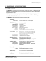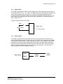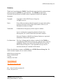
1
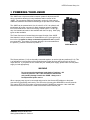
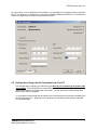
JNIOR Series 4 A Network I/O Resource Utilizing the JAVA Platform Getting Started Manual Release 1.0 NOTE: JANOS OS 1.1 or greater required INTEG Process Group, Inc. 2919 East Hardies Rd, First Floor Gibsonia, PA 15044 PH (724) 933-9350 FAX (724) 443-3553 www.integpg.com [email protected] © 2015 INTEG Process Group, Inc. All Rights Reserved Last updated on: April 29, 2015 INTEG Process Group, Inc TABLE OF CONTENTS 1 2 3 4 WHAT’S INCLUDED ............................................................................................................................ 2 INTRODUCTION TO THE JNIOR........................................................................................................ 3 POWERING YOUR JNIOR .................................................................................................................. 5 COMMUNICATIONS SET-UP ............................................................................................................. 6 4.1 Configuration Using the JNIOR Support Tool ......................................................................... 6 4.2 Configuration Using a Serial Connection from Your PC ......................................................... 7 4.3 JNIOR Web Page .................................................................................................................. 11 5 INTERACTING WITH THE JNIOR .................................................................................................... 13 5.1 Web-Based Browser Screen ..................................................................................................... 13 5.2 Serial-to-Ethernet Server ........................................................................................................... 13 5.3 Serial Control PLUS Program .................................................................................................... 13 5.4 Task Manager Program ............................................................................................................. 13 5.5 OPC Server................................................................................................................................ 14 5.6 Modbus – Master and Slave ...................................................................................................... 14 5.7 Windows DLL ............................................................................................................................. 14 5.8 Custom Communications via JNIOR Communications Protocol ............................................... 14 5.9 Custom Applications Running on the JNIOR............................................................................. 14 6 HARDWARE SPECIFICATIONS ....................................................................................................... 15 6.1 JNIOR Series 4 .......................................................................................................................... 15 6.1.1 Wiring Diagram ...................................................................................................................... 16 6.1.2 Digital Inputs .......................................................................................................................... 17 6.1.3 Relay Outputs ........................................................................................................................ 17 JNIOR A Network I/O Resource Getting Started Manual – Series 4 1 INTEG Process Group, Inc 1 WHAT’S INCLUDED The JNIOR is shipped with the following items: JNIOR – one of the following models with the ONLY difference being the I/O mix o o o JNIOR Model 410 JNIOR Model 412 JNIOR Model 414 Catalog No. JNR-100-004B Catalog No. JNR-200-004B Catalog No. JNR-300-004B 8 inputs 8 outputs 4 inputs 12 outputs 12 inputs 4 outputs Connector Kit – 5-Piece o o o Connection Power Digital Inputs Relay Outputs Type 4 Pin terminal connector 8 Pin terminal connector 8 Pin terminal connector Quantity 1 2 2 Power Adapter (optional) – includes extra 4 pin terminal connector JNIOR Support Documentation Available on our website at http://www.integpg.com/support/ o o o o JNIOR JNIOR Support Tool – PC Software for configuring your JNIOR IP settings and updates Documentation – User Manuals, Technical Manuals and Drawings JNIOR Software Development Kit (SDK) and Sample Software Miscellaneous Tools A Network I/O Resource Getting Started Manual – Series 4 2 INTEG Process Group, Inc 2 INTRODUCTION TO THE JNIOR JNIOR, a Network I/O Resource utilizing the JAVA™ platform, is a cost effective automation controller that communicates over a network using TCP/IP via an Ethernet Port or via its serial port. The JNIOR is a general-purpose automation controller and I/O device that is easily configurable for control and monitoring of your equipment or process via the built-in web pages or by enabling the built-in software applications or via interaction with an application running on another computer or by adding your own applications. The TCP/IP connectivity allows the JNIOR to be easily connected with other computers over an Ethernet network or the Internet using the JNIOR protocol, web sockets, the standard Modbus TCP protocol and/or via OPC using a third party OPC Server for Modbus software package. Custom protocols can also be added. The JNIOR Series 4 contains a modern web server to host its own dynamic web pages using web sockets and HTML5 code or custom web pages developed by INTEG or the end user. The JNIOR contains File Transfer Protocol (FTP) and Telnet servers, for transferring data files, loading software, system configuration, and maintenance. The JNIOR is also an e-mail client capable of sending e-mails, with attachments, based on alarms or system events. The JNIOR Series 4 can make ‘secure’ web and other connections. The JNIOR contains a mix of digital inputs and relay outputs, and can be expanded with plug and play analog expansion modules (4 – 20 mA, +/- 10 VDC, RTD), 4 Relay Output expansion modules (low or high voltages), LED Dimmer module, User Control Panel and/or digital temperature sensors. The JNIOR includes applications that can be easily enabled or added and configured by the user: Modbus Slave and/or Modbus Master – allows the JNIOR to make a Modbus connection and act as either (or both) a slave and a master. Data can be transferred internally between the two. SNMP – Simple Network Management Protocol – allows the JNIOR to send ‘traps’ when an input or output goes on or off to network monitoring software applications Serial-to-Ethernet Server – allows the JNIOR to act as a serial to Ethernet converter Serial Control PLUS – allows the user to interact with the JNIOR I/O using ASCII commands via the serial port and/or an Ethernet connection Task Manager – allows the user to configure Tasks to run Actions at various times, or based on Events, to control outputs, log data or send e-mail Cinema – allows the JNIOR to execute macros to fully automate a movie theatre and other presentation facilities to control the lights, sound, projector, etc. Utility Usage Monitoring – allows the JNIOR to monitor and log the usage of utilities such as electricity, gas, water, etc. and store the data on the JNIOR for user retrieval and/or viewing via the built-in JNIOR web page. JNIOR A Network I/O Resource Getting Started Manual – Series 4 3 INTEG Process Group, Inc For custom applications, a Java Virtual Machine (JVM) is also available on the JNIOR for implementing application programs written in Java. Please contact INTEG Process Group for more details. Uses for the JNIOR include: JNIOR Cinema automation Lighting and presentation control Remote monitoring and control of equipment Utility usage monitoring and reporting Data acquisition and logging Serial-to-Ethernet interface Interface with legacy systems Linking I/O to existing operator interfaces E-mail alert A Network I/O Resource Getting Started Manual – Series 4 4 INTEG Process Group, Inc 3 POWERING YOUR JNIOR The JNIOR uses a 2-piece terminal connector system for all power and I/O wiring connections allowing for easy installation and/or removal of the JNIOR. The connection details are described in section 6 of this manual. Additional installation information and drawings are provided on our website. The JNIOR can be powered with 12 to 24 volts AC or DC. An optional, wall transformer (AC power converter) for North American outlets is available from INTEG that can be used for converting 120/240 VAC to 12 VDC @ 1 amp. An international model is also available with the Euro plug. Other plug types are also available. The Power Connector is located along the upper left edge of the JNIOR. Note that this is a 4-pin connector. If numbered from one (1) through four (4) from left to right power is always connected to positions 2 and 3 (middle two connectors). The polarity is irrelevant although it is recommended that the positive (+) lead be connected to position 2. JNIOR Model 410 The left two positions (1 & 2) are internally connected together, as are the right two positions (3 & 4). This is to facilitate the interconnection of the supplied power to other devices and circuits such as input or output devices. If you power the I/O circuits with your JNIOR power supply, please make sure the power supply is sized appropriately. WARNING Do not connect the transformer leads both to Positions 1 & 2 or both to positions 3 & 4. This will short the transformer and possibly damage it and/or the JNIOR. Always use a fused/protected power source. When a proper power source is connected and turned on the leftmost LED adjacent to the power connector will glow BLUE continuously. The LED to the right may glow ORANGE for several seconds. This orange STATUS LED remains on through most of the JNIOR boot sequence. Later it will flash whenever an external connection is made to the JNIOR via the Ethernet port. JNIOR A Network I/O Resource Getting Started Manual – Series 4 5 INTEG Process Group, Inc 4 COMMUNICATIONS SET-UP In order to utilize your JNIOR via the Ethernet network, you will most likely have to adjust the JNIOR IP configuration to work on your network. The JNIOR is shipped with the default IP Address of 10.0.0.201 The JNIOR supports DHCP for dynamic setting of the JNIOR IP address by a network server, however, this method is normally not recommended because the IP address of the JNIOR may change and prevent your application from finding the JNIOR. The default JNIOR setting is to have DHCP disabled. If the above address will not work on your network, then there are two ways to configure your JNIOR IP settings: By using the JNIOR Support Tool (Beacon tab) provided on our website at the following link: http://www.integpg.com/support/jnior/ Via the RS232 Serial Port and a command line window available via the JNIOR Support Tool 4.1 Configuration Using the JNIOR Support Tool The easiest way to configure your JNIOR is via the JNIOR Support Tool and the JNIOR Beacon functionality. Beacon is built into every JNIOR Series 4. The JNIOR Support Tool is available on our website. The JNIOR Support Tool Manual is installed on your PC under Start – Programs – INTEG – Support Tool. Simply install the JNIOR Support Tool and then connect an Ethernet cable to your JNIOR and power-up the JNIOR. The JNIOR Support Tool will automatically detect the JNIOR (as long as the JNIOR is on the same local Ethernet network) when the JNIOR completes its boot. Or you can right click in the Beacon Tab and select Query New or Query All. The Manage IP List feature allows you to manually enter JNIOR IP addresses so they can be found across a VPN, routers, etc. Please see the JNIOR Support Tool Manual for additional details on how to use the other features of the JNIOR Support Tool. You may need to adjust your Firewall settings for Beacon to work. JNIOR A Network I/O Resource Getting Started Manual – Series 4 6 INTEG Process Group, Inc By “right clicking” on your JNIOR listed in the window, you can display the Configuration pop-up as shown below. At a minimum, you need to type in your desired JNIOR IP Address and click OK. You should then be able to interact with your JNIOR via your Ethernet network. 4.2 Configuration Using a Serial Connection from Your PC The alternate way to configure your JNIOR is via the RS-232 port located along the bottom edge of the JNIOR. The lower RS232 port is the JNIOR command console port and is a DB-9 connector that utilizes a standard, straight-through, serial cable. You will need to use a USB to DB-9 serial cable to work with your computer. You will need to communicate with the JNIOR using a Command Line window that is available from the JNIOR Support Tool. “Right-click” in the white area on the Beacon tab and select Command Line as shown below. JNIOR A Network I/O Resource Getting Started Manual – Series 4 7 INTEG Process Group, Inc Your COM properties should be set for 115200 baud, 8 bits, no parity, 1 stop bit, and no handshaking (flow control) and appear as shown below (these are the default settings for the RS232 port): If you power-up your JNIOR after you have connected your serial cable to the JNIOR and opened a command line session, you will see the boot dialog. If you powered-up your JNIOR before you have opened a command line session, you will not see the Boot dialog. In either case, the JNIOR is ready to accept a login. You may need to hit the ENTER key to obtain the login prompt. Enter a username for the JNIOR (default is “jnior”) and enter a password for the JNIOR (default is “jnior”). If you are successful, your screen should look similar to the following: JNIOR A Network I/O Resource Getting Started Manual – Series 4 8 INTEG Process Group, Inc You will use the ipconfig command to configure the JNIOR Ethernet port for your required static (fixed) IP Address. The ipconfig command has several options associated with it and they can be viewed by typing, help ipconfig at the command line prompt. The options are shown below: In order to properly configure your JNIOR network settings using ipconfig, use the command shown below. You must enter, at a minimum, your IP address and a mask: ipconfig -a IP -m MASK where: IP MASK = desired IP address = IP mask On a private network, the IP address may be something like 192.168.1.10. A common mask would be 255.255.255.0. The command would then look as follows: ipconfig -a 192.168.1.10 -m 255.255.255.0 Other settings, such as a gateway, primary and secondary domain name servers, and a mail host, may or may not be needed. JNIOR The gateway often, although not always, is the .1 of the IP address. In the above example it would be 192.168.1.1. It allows the JNIOR to get to another segment of the Ethernet network. The primary and secondary domain name servers (DNS) provide resolution for the aliases that are used for the IP addresses of other devices on the network and for e-mail addresses. If other devices are referred to by their IP address only and not by name or the JNIOR e-mail feature is not being used, then neither DNS server has to be setup. The JNIOR Series 4 email system requires a Mail Host. Please see the Email Application Note for additional details on how to configure the JNIOR Series 4 to send email. A Network I/O Resource Getting Started Manual – Series 4 9 INTEG Process Group, Inc Typing in the above command will result in the following. Your IP settings can be checked by simply typing the ipconfig command at the command line and pressing <enter>: While you are logged into the JNIOR, you can also set your date and time. The JNIOR date and time are set during the factory build to GMT (also now referred to as MIT). The JNIOR has a real time clock that is battery backed so you may just have to set your time zone. The GMT time should be approximately correct. If the JNIOR is connected to the Ethernet, the time can automatically be synced via the JNIOR Network Time Protocol (NTP). The default website the JNIOR checks is clock.isc.org. However, for this NTP server to work, you will need to set a DNS and possibly a gateway address. You can change the NTP Server registry key to the IP address of any server/computer on the network that will respond to an NTP request or you can use any domain name that will provide the NTP functionality. You can set your JNIOR date and time using the date command. Typing help date will provide you with the command format. When finished with your Command Line session, type logout or bye on the command line to end your session and then close the Command Line window. For more information concerning additional commands available to the user through a command line or a Telnet session, please see the Command Line Communications Manual on our website. JNIOR A Network I/O Resource Getting Started Manual – Series 4 10 INTEG Process Group, Inc 4.3 JNIOR Web Page The JNIOR Series 4 contains both a ‘dynamic’ web page and a configuration web page that work with Microsoft Internet Explorer, Google Chrome, Fire Fox and other browsers. The classic ‘configuration’ web page requires the Java plug-in (available on most computers or at www.java.com). PLEASE NOTE: The dynamic web page requires a ‘modern web browser’ which is defined as Internet Explorer 10 or greater, Google Chrome or Firefox. You can launch the JNIOR Web page from the Beacon tab in the JNIOR Support Tool or by manually entering the JNIOR IP address in your browser address line. To manually launch the JNIOR web page, open your browser and in the address line of the browser type your JNIOR IP address, for example: http://10.0.0.201 Dynamic Web Page (10.0.0.201 is the default IP address) http://10.0.0.201/configure Configuration Web Page (10.0.0.201 is the default) NOTE: The JNIOR configuration web page communicates back to the JNIOR using port 9200 After the JNIOR web page is loaded, the user is asked to login with a valid username and password. You can use the default username (jnior) and default password (jnior). The new ‘dynamic’ JNIOR web page available with the Series 4 will be launched in your browser as shown below. JNIOR A Network I/O Resource Getting Started Manual – Series 4 11 INTEG Process Group, Inc If you ‘click’ on the Show Menu link on the left side of the JNIOR dynamic web page, you will see the option to launch the Classic Configuration Web Page. This is the same web page that is used on the JNIOR Series 3. It requires the Java plug-in on your PC to run. This will launch the typical (or ‘classic’) JNIOR web page used to Configure the JNIOR. Please see the Web Based Interface Manual installed with the JNIOR Support Tool at Start – Programs – INTEG – JNIOR and also located on our website for more details. JNIOR A Network I/O Resource Getting Started Manual – Series 4 12 INTEG Process Group, Inc 5 INTERACTING WITH THE JNIOR Once you have your new JNIOR set up on the network, the next step is to determine the best way to integrate the JNIOR into your application. There are several ways that your new JNIOR can be utilized and integrated into your application. A few of these are highlighted below, with a detailed discussion of each being contained in other documents. 1. 2. 3. 4. 5. 6. 7. 8. 9. Web-Based Browser User Interface for Monitoring and Control Serial-to-Ethernet Server Serial Control Plus Program Task Manager Program OPC Server Modbus Server Windows DLL that utilizes the JNIOR Communications Protocol Custom Communications via the JNIOR Communications Protocol Custom applications running on the JNIOR 5.1 Web-Based Browser Screen The JNIOR contains its own web pages for system monitoring, manual control and configuration. A complete explanation of how to use the supplied web pages is in the Web Based Interface Manual installed with the JNIOR Support Tool at Start – Programs – INTEG – JNIOR or located on our website. 5.2 Serial-to-Ethernet Server The Serial-to-Ethernet function for the JNIOR is a software application that runs on the JNIOR and allows the JNIOR to act as a converter between a serial device connected to the JNIOR and a remote application communicating to the JNIOR via the Ethernet network using TCP/IP. A complete explanation of how to use the Serial-to-Ethernet server is in the Serial-to-Ethernet Manual located on our website. 5.3 Serial Control PLUS Program The Serial Control Plus function for the JNIOR is a software application that runs on the JNIOR and allows the user to interact with the JNIOR I/O using simple ASCII commands via the serial port or an Ethernet connection. The user can control the relay outputs (on, off, pulse) and receive the status of the digital inputs (on, off) and counters via the serial port (or via the Ethernet). A complete explanation of how to use the Serial Control Plus Program is described in the Serial Control Plus Manual located on our website. 5.4 Task Manager Program Task Manager is a program that runs on the JNIOR to provide control, logging and notification capabilities based on time and events. A complete explanation of how to use the Task Manager Program is in the Task Manager Manual located on our website. JNIOR A Network I/O Resource Getting Started Manual – Series 4 13 INTEG Process Group, Inc 5.5 OPC Server The JNIOR supports access to data points via OPC communications. You can use any third party OPC Server that works with the Modbus communications protocol. 5.6 Modbus – Master and Slave The JNIOR supports access to the JNIOR I/O via Modbus TCP communications over the Ethernet network. The JNIOR can serve as a Modbus Slave and is accessed by an external Modbus Master. The JNIOR can also act as a Modbus Master and access other ‘slaves’ via Modbus. Data acquired as a Modbus Master can be moved to internal registers so that external Modbus Masters can access the data via the Modbus Slave connection. For detailed information on implementing the Modbus connectivity, please see the document Modbus Protocol Implementation located on our website. 5.7 Windows DLL The JNIOR Windows DLL allows the user to access many of the JNIOR functions through easy to use API calls. By taking advantage of these predefined API calls, the user can easily design custom applications which access all available JNIOR data and functionality without having to know the details behind the JNIOR communications structure. There are many functions in the DLL to accommodate the needs of the developer. For detailed information on what API calls are available and for detailed instructions on how to take advantage of this Windows DLL, please see the document Windows Library Reference located on our website. 5.8 Custom Communications via JNIOR Communications Protocol The JNIOR uses a series of custom, well-defined packets of information to send and receive data and requests for data from the JNIOR to whatever application is communicating with it. By implementing the JNIOR protocol communications within their application directly, the user can establish an efficient communications link with the JNIOR and take advantage of the all the JNIOR functionality. For detailed information on the structure of the JNIOR communications protocol, please see the document JNIOR Communications Protocol located on our website. 5.9 Custom Applications Running on the JNIOR Custom applications can be developed using Java to run on the JNIOR. Custom web pages using Java script, web sockets, HTML5 and other standard web-based utilities can also be developed to be served by the JNIOR. Please visit our website for our Software Development Kit (SDK). JNIOR A Network I/O Resource Getting Started Manual – Series 4 14 INTEG Process Group, Inc 6 HARDWARE SPECIFICATIONS 6.1 JNIOR Series 4 The JNIOR Series 4 contains a 32-bit microprocessor, 32 MB FLASH memory, 32 MB dynamic RAM, 2 MB battery-backed static RAM memory, and the JNIOR operating system (JANOS) with an integral Java Virtual Machine (JVM). JNIOR’s circuit board resides in a protective case with an integral low voltage power supply and a variety of general-purpose I/O points. External communications are handled via the Ethernet port, Auxiliary Serial Port and RS232 Serial Port. The JNIOR Series 4 specifications are provided in the following table: Power Input Input Voltage 12 to 24 Volts DC or AC, < 400 mA typical Digital Inputs Range Logic Low input Logic High input Input Resistance Response time Counter capability Isolation Functions 0 to 30 Volts AC/DC 0 to 1 Volt 2 to 30 Volts 1.2 K ohm nominal 1 millisecond 2000 Hz Max (each input) Optically Isolated Latching capability – as fast as 1 millisecond Relay Outputs Type Contact Ratings Pulse Resolution SPST, Form A – 1 Normally Open Contact (Two relays are Form C and configurable as Normally Open or Normally Closed to the termimals) 1 Amp @ 24 Volts AC/DC 1 millisecond pulse increments RS232 Serial Port (1) Communication Default Settings DB-9 female with 9 pin DTE pinout Configurable based on application 115,200 BPS, 8 Data bits, No parity, 1 stop bit, No Flow Control Aux Serial Port (1) Communication Default Settings Auxiliary Serial Port – RS232, RS422, RS485 Configurable based on application 9600 BPS, 8 Data bits, No parity, 1 stop bit, No Flow Control DB-9 Female Connector Ethernet (1) Connection Speed JNIOR RJ-45 Connection 10/100 Mb Auto-Negotiated, Full Duplex Sensor Port (1) RJ-12 Connection for Expansion Modules Certification TUV Safety Mark (60950), CE, FCC Class A A Network I/O Resource Getting Started Manual – Series 4 15 INTEG Process Group, Inc 6.1.1 Wiring Diagram The following diagram provides the user with the pin-outs of the digital inputs and digital outputs for the JNIOR Model 410. Please contact INTEG Process Group for additional assistance. JNIOR + + + + - 1 2 3 4 5 6 7 8 1 2 3 4 5 6 7 8 + + + + - + + + + - 1 2 3 4 5 6 7 8 1 2 3 4 5 6 7 8 + + + + - A Network I/O Resource Getting Started Manual – Series 4 16 INTEG Process Group, Inc 6.1.2 Digital Inputs The JNIOR is equipped with optically isolated digital inputs. Each digital input can accept AC or DC voltage sources in the 0 – 30 V range. An LED associated with each digital input displays the current electrical status of the input (off or on). Isolation of each digital input allows you to connect input signals to different voltage sources without the addition of isolation devices. The input voltage must be greater than 2 VDC for the input to register as “on” and then less than 1 VDC to register as “off”. A typical connection would be as follows: Input + Power Source Digital Input Or Counter Input _ 6.1.3 Relay Outputs The JNIOR is equipped with Relay Outputs with most of them being a Form A SPST relay (1 Normally Open Contact) and two of them being a Form C SPST relay (1 Normally Open Contact and 1 Normally Closed Contact – jumper selectable as to which one is available on the JNIOR terminals by removing the lid and changing the jumper setting. Normally Open is the default.) Each relay output is independent and isolated from the other relay output. Each relay contact rating is 1A @ 24VDC and the voltage source must be in the range of 5 – 30V AC or DC. A typical connection would be configured as follows: Relay Output ROUT + ROUT - JNIOR A Network I/O Resource Getting Started Manual – Series 4 Output Device Power Source 17 INTEG Process Group, Inc Summary Thank you for purchasing the JNIOR. Hopefully this manual made the getting-to-know process of your new JNIOR very quick and easy. The JNIOR has many more wonderful tools and features available, and are explained in detail in the supplied documents. Copyright Copyright 2015 INTEG Process Group, Inc. All rights reserved. Notice Every effort was made to make this manual as accurate and useful as practical at the time of the writing of this manual. However, all information is subject to change. Trademarks Trademarks are the property of their respective holders. Java is a trademark or registered trademark of Oracle (Sun Microsystems, Inc.) in the United States and other countries. Microsoft, Windows, MS-DOS and Internet Explorer are registered trademarks of Microsoft Corporation. Use Restrictions This User’s Manual and the software contained in the JNIOR are copyrighted by INTEG Process Group, Inc. and may not be copied or reproduced without prior consent from INTEG Process Group, Inc. INTEG Process Group, Inc. is not responsible for any errors or omissions that may be contained in this manual. Please do not hesitate to contact our JNIOR team at INTEG Process Group, Inc. We can be reached via phone, fax or e-mail as follows: INTEG Process Group, Inc. 2919 E. Hardies Road 1st Floor Gibsonia, PA 15044 www.integpg.com [email protected] PH (724) 933-9350 extension 20 FAX (724) 443-3553 JNIOR A Network I/O Resource Getting Started Manual – Series 4 18