1
HORNER ELECTRIC, INC
ORION-SERIES
GIU5xx
GRAPHICAL INTERFACE UNIT
USER'S MANUAL
Release 1.0
COPYRIGHT©1997 - All Rights Reserved
Horner Electric, Inc.
Indianapolis, IN 46201
12-8-97
MAN0021-01
Windows, Windows-95, and Window-NT are trademarks or registered trademarks of Microsoft
Corporation
IBM is a registered trademark of International Business Machines Corporation.
This document is based on information available at the time of its publication. While efforts have
been made to be accurate, the information contained herein does not purport to cover all details
or variations in hardware or software, nor to provide for every possible contingency in connection
with installation, operation, or maintenance. Features may be described herein which are not
present in all hardware or software variations. Horner Electric assumes no obligation of notice to
holders of this document with respect to subsequent changes made.
Horner Electric makes no representation or warranty, expressed, implied, or statutory with
respect to, and assumes no responsibility for the accuracy, completeness, sufficiency, or
usefulness of the information contained herein. No warranties of merchantability or fitness for
purpose shall apply.
This document printed02/10/98 1:02 PM
GIU
Page i
Editor
Users
Manual
TABLE OF CONTENTS
CONVENTIONS USED IN THIS MANUAL _____________________________________________ 1
TYPOGRAPHICAL CONVENTIONS ________________________________________________________ 1
OPERATIONAL CONVENTIONS___________________________________________________________ 2
GRAPHICAL CONVENTIONS _____________________________________________________________ 3
SYSTEM REQUIREMENTS __________________________________________________________ 4
INSTALLING THE EDITOR __________________________________________________________ 4
REQUIRED FILES __________________________________________________________________ 4
OPTIONAL FILES __________________________________________________________________ 5
CONCEPTUAL OVERVIEW __________________________________________________________ 6
THE HARDWARE _______________________________________________________________________ 6
THE SOFTWARE ________________________________________________________________________ 7
OBJECTS_______________________________________________________________________________ 8
PAGES _________________________________________________________________________________ 8
SCRIPTS _______________________________________________________________________________ 9
VARIABLES ___________________________________________________________________________ 10
OPERATIONAL ORDER ____________________________________________________________ 11
FUNCTION KEYS ______________________________________________________________________ 11
SHOWPAGE ___________________________________________________________________________ 12
THE I/O SCAN _________________________________________________________________________ 14
THE MENUING SYSTEM ___________________________________________________________ 16
THE MAIN MENU ______________________________________________________________________ 16
THE FILES SUB-MENU__________________________________________________________________ 16
NEW PROJECT _______________________________________________________________________________17
OPEN PROJECT_______________________________________________________________________________17
SAVE PROJECT_______________________________________________________________________________17
SAVE PROJECT AS ___________________________________________________________________________17
SAVE RUNTIME BINARY ______________________________________________________________________17
PAGE SETUP _________________________________________________________________________________18
PRINT _______________________________________________________________________________________18
EXIT ________________________________________________________________________________________18
MOST RECENTLY USED LIST __________________________________________________________________18
THE EDIT SUB-MENU __________________________________________________________________ 19
UNDO _______________________________________________________________________________________19
CUT_________________________________________________________________________________________19
COPY _______________________________________________________________________________________19
PASTE_______________________________________________________________________________________19
DELETE _____________________________________________________________________________________20
SELECT ALL _________________________________________________________________________________20
Copyright 1997 Horner Electric, Inc.
All Rights Reserved
Page ii
Manual
GIU Editor Users
THE PROJECT SUB-MENU ______________________________________________________________ 20
VARIABLES__________________________________________________________________________________20
BITMAPS ____________________________________________________________________________________20
KEYS________________________________________________________________________________________20
GLOBAL DECLARATIONS _____________________________________________________________________21
INITIAL SCRIPT ______________________________________________________________________________21
CONTROL SCRIPT ____________________________________________________________________________21
ALARM SCRIPT ______________________________________________________________________________21
DEVICE DRIVERS ____________________________________________________________________________21
GIU MODEL__________________________________________________________________________________21
DEFAULT DISPLAY COLOR____________________________________________________________________21
HOME PAGE NUMBER/NAME __________________________________________________________________21
CHECK FOR ERRORS__________________________________________________________________________21
VIEW ERROR BOX ____________________________________________________________________________21
THE PAGE SUB-MENU _________________________________________________________________ 22
PROPERTIES _________________________________________________________________________________22
FUNCTION KEYS _____________________________________________________________________________22
SCRIPT ______________________________________________________________________________________22
OBJECT ORDER ______________________________________________________________________________22
COPY FROM PAGE____________________________________________________________________________22
DELETE ALL CONTENTS ______________________________________________________________________22
GOTO PAGE__________________________________________________________________________________23
PREVIOUS PAGE _____________________________________________________________________________23
NEXT PAGE __________________________________________________________________________________23
THE OBJECT SUB-MENU ______________________________________________________________________24
WIZARD _____________________________________________________________________________________24
SCRIPT ______________________________________________________________________________________24
ALIGN OBJECTS______________________________________________________________________________24
MAKE SAME SIZE ____________________________________________________________________________24
THE TARGET SUB-MENU_______________________________________________________________ 25
CONNECT ___________________________________________________________________________________25
DISCONNECT ________________________________________________________________________________25
GIU TAG NAMES _____________________________________________________________________________25
READ PROGRAM _____________________________________________________________________________26
WRITE PROGRAM ____________________________________________________________________________26
VERIFY PROGRAM ___________________________________________________________________________26
DELETE PROGRAM ___________________________________________________________________________26
STATUS _____________________________________________________________________________________26
RESTART PROGRAM__________________________________________________________________________26
SUSPEND PROGRAM __________________________________________________________________________27
RESUME PROGRAM___________________________________________________________________________27
TERMINATE PROGRAM _______________________________________________________________________27
INSPECT MEMORY ___________________________________________________________________________27
AUTO-RESTART AFTER WRITE ________________________________________________________________27
AUTO-CONNECT TO LAST TARGET ____________________________________________________________27
ATTACH SOURCE CODE TO WRITES ___________________________________________________________27
THE OPTIONS SUB-MENU ______________________________________________________________ 28
TEXT BORDERS ______________________________________________________________________________28
GENERATE .STK ON COMPILE _________________________________________________________________28
THE TOOLS SUB-MENU ________________________________________________________________ 29
REGENERATE SCRIPTS FROM WIZARDS ________________________________________________________29
WRITE GIU FIRMWARE _______________________________________________________________________29
THE WINDOW SUB-MENU______________________________________________________________ 30
NEW WINDOW _______________________________________________________________________________30
Copyright 1997 Horner Electric, Inc.
All Rights Reserved
GIU
Page iii
Editor
Users
Manual
TILE HORIZONTALLY ________________________________________________________________________30
TILE VERTICALLY ___________________________________________________________________________30
CASCADE ___________________________________________________________________________________30
CLOSE ALL __________________________________________________________________________________30
TOOLBAR ___________________________________________________________________________________30
STATUS BAR_________________________________________________________________________________30
VISIBLE WINDOW LIST _______________________________________________________________________31
USING THE EDITOR_______________________________________________________________ 32
INVOCATION __________________________________________________________________________ 32
A SIMPLE OVERVIEW __________________________________________________________________ 32
CONNECTION TO THE GIU DEVICE ______________________________________________________ 34
INTERACTIONS BETWEEN THE EDITOR AND THE GIU DEVICE ____________________________ 34
WRITING A PROGRAM ____________________________________________________________ 35
DEFINING AND SETTING UP DEVICE DRIVERS ___________________________________________ 35
ADDING A DEVICE DRIVER _____________________________________________________________ 36
Setup ________________________________________________________________________________________37
EDITING OR REMOVING A DEVICE DRIVER ______________________________________________ 37
SETTING UP THE DEVICE DRIVER_______________________________________________________ 38
DEFINING (ADDING) VARIABLES________________________________________________________ 38
DEFINING (ADDING) VARIABLES: A PRACTICAL EXAMPLE________________________________ 41
ASSOCIATING VARIABLES TO I/O POINTS _______________________________________________ 42
Read_________________________________________________________________________________________43
Write ________________________________________________________________________________________43
Suppress Initial Write, If Zero ____________________________________________________________________43
Unscale On Write ______________________________________________________________________________43
CREATING PAGES _____________________________________________________________________ 44
SETTING PAGE PROPERTIES __________________________________________________________________44
COPYING A PAGE ____________________________________________________________________________45
DELETE ALL CONTENTS FROM A PAGE ________________________________________________________45
DEFINING FUNCTION KEYS ____________________________________________________________ 46
SELECTING A FUNCTION KEY_________________________________________________________________47
ADDING COMMANDS TO THE KEY'S SCRIPT ____________________________________________________48
NON-EDITABLE COMMANDS __________________________________________________________________48
EDITING PRE-DEFINED COMMANDS ___________________________________________________________49
ADDING MANUAL SCRIPTS ___________________________________________________________________51
ADDING OBJECTS _____________________________________________________________________ 52
SELECTING PREVIOUSLY PLACED OBJECTS ____________________________________________________52
DE-SELECTING A PREVIOUSLY PLACED OBJECT________________________________________________52
DELETING A SINGLE OBJECT _________________________________________________________________53
DEFINING THE OBJECT _______________________________________________________________________54
SETTING OBJECT PROPERTIES ________________________________________________________________55
SETTING OBJECT INDICATORS ________________________________________________________________56
SETTING INDICATOR RANGES ________________________________________________________________57
REPAINT OBJECT WHEN ______________________________________________________________________59
APPLY ______________________________________________________________________________________59
THE "DEFAULT" RANGE ______________________________________________________________________59
SELECTING FONTS ___________________________________________________________________________60
SELECTING MULTIPLE OBJECTS_______________________________________________________________60
Copyright 1997 Horner Electric, Inc.
All Rights Reserved
Page iv
Manual
GIU Editor Users
DELETING MULTIPLE OBJECTS________________________________________________________________61
MOVING OBJECTS____________________________________________________________________________61
ALIGNING OBJECTS __________________________________________________________________________61
MAKE ALL OBJECTS THE SAME SIZE___________________________________________________________61
DEFINING I/O POINTS__________________________________________________________________ 62
USING BITMAPS __________________________________________________________________ 63
TAG THE BITMAP _____________________________________________________________________ 63
Tag Name ____________________________________________________________________________________64
File Name ____________________________________________________________________________________64
Browse _______________________________________________________________________________________64
REMOVING TAGGED BITMAPS _________________________________________________________ 64
ASSOCIATING THE BITMAP TAG TO THE SCREEN _______________________________________ 64
DE-ASSOCIATING THE BITMAP TAG ____________________________________________________ 65
WRITING SCRIPTS ________________________________________________________________ 66
AVAILABLE SCRIPTS __________________________________________________________________ 66
THE INITIAL SCRIPT __________________________________________________________________________66
THE CONTROL SCRIPT ________________________________________________________________________66
THE ALARM SCRIPT __________________________________________________________________________66
THE PAGE SCRIPTS ___________________________________________________________________________66
THE OBJECT SCRIPTS _________________________________________________________________________66
THE FUNCTION KEY SCRIPTS _________________________________________________________________67
ADDING OR EDITING A SCRIPT _________________________________________________________ 67
SCRIPT TEXT EDITING_________________________________________________________________ 68
PRINTING ________________________________________________________________________ 69
PAGE SETUP __________________________________________________________________________ 69
HEADER_____________________________________________________________________________________69
FOOTER _____________________________________________________________________________________69
MARGINS____________________________________________________________________________________70
PRINT ________________________________________________________________________________ 70
PAGES ______________________________________________________________________________________70
OBJECT PROPERTIES / SCRIPTS ________________________________________________________________71
GLOBAL SCRIPTS ____________________________________________________________________________71
GLOBAL VARIABLES _________________________________________________________________________71
I/O SETUP____________________________________________________________________________________71
COMMUNICATING WITH THE GIU__________________________________________________ 72
MENU SWITCHES _____________________________________________________________________ 72
AUTO-RESTART AFTER WRITE ________________________________________________________________72
AUTO-CONNECT TO LAST TARGET ____________________________________________________________72
ATTACH SOURCE CODE TO WRITES ___________________________________________________________72
SAVING THE PROGRAM _______________________________________________________________ 72
CHECKING THE PROGRAM FOR ERRORS ________________________________________________ 72
GIU TAG NAMES ______________________________________________________________________ 73
Add _________________________________________________________________________________________74
Edit _________________________________________________________________________________________74
Remove ______________________________________________________________________________________74
Copyright 1997 Horner Electric, Inc.
All Rights Reserved
GIU
Page v
Editor
Users
Manual
CONNECTING TO A GIU ________________________________________________________________ 75
CHECKING GIU STATUS ________________________________________________________________ 76
WRITE A PROGRAM TO THE GIU ________________________________________________________ 77
READ A PROGRAM FROM THE GIU ______________________________________________________ 77
VERIFYING A PROGRAM _______________________________________________________________ 77
DELETING A PROGRAM ________________________________________________________________ 78
SUSPENDING A PROGRAM _____________________________________________________________ 78
RESUMING A PROGRAM _______________________________________________________________ 78
RESTARTING A PROGRAM _____________________________________________________________ 78
TERMINATING A PROGRAM ____________________________________________________________ 78
WHAT TO DO IF A COMMUNICATIONS ERROR IS PRESENT________________________________ 79
THE TOOLBARS __________________________________________________________________ 80
FILE HANDLING TOOLS ________________________________________________________________ 80
PROJECT TOOLS_______________________________________________________________________ 81
OBJECT HANDLING TOOLS _____________________________________________________________ 81
TARGET HANDLING TOOLS ____________________________________________________________ 82
OBJECT SELECTION TOOLS ____________________________________________________________ 82
GIU BASIC _______________________________________________________________________ 84
PREDEFINED VALUES__________________________________________________________________ 84
Boolean Values ________________________________________________________________________________84
Colors _______________________________________________________________________________________84
Alignment ____________________________________________________________________________________85
Data Types____________________________________________________________________________________85
MATH OPERATORS ____________________________________________________________________ 85
CONSTANTS __________________________________________________________________________ 86
VARIABLES ___________________________________________________________________________ 86
VARIABLE DECLARATION ____________________________________________________________________87
VARIABLE SCOPE ____________________________________________________________________________88
THE VARIANT DATA TYPE ____________________________________________________________________89
OBJECT PROPERTIES __________________________________________________________________ 89
Available Object Properties_______________________________________________________________________90
SYSTEM EVENTS ______________________________________________________________________ 93
AVAILABLE STATEMENTS _____________________________________________________________ 95
PROGRAM FLOW STATEMENTS _______________________________________________________________95
MATH FUNCTIONS ___________________________________________________________________________96
USER INTERFACE STATEMENTS AND FUNCTIONS ______________________________________________97
STRING ORIENTED FUNCTIONS _______________________________________________________________99
MISCELLANEOUS FUNCTIONS________________________________________________________________101
APPENDIX A -- KEYBOARD SHORTCUTS ___________________________________________ 105
APPENDIX B - Available Objects _____________________________________________________ 107
ARROWS ___________________________________________________________________________________107
Copyright 1997 Horner Electric, Inc.
All Rights Reserved
Page vi
Manual
GIU Editor Users
BAR GRAPH_________________________________________________________________________________107
TANK ______________________________________________________________________________________107
HOPPER ____________________________________________________________________________________107
LINES ______________________________________________________________________________________107
METER _____________________________________________________________________________________108
MOTOR_____________________________________________________________________________________108
PIPES_______________________________________________________________________________________108
PUMPS _____________________________________________________________________________________108
STATUS LIGHTS (Large and Small)______________________________________________________________108
TEXT_______________________________________________________________________________________108
THERMOMETER_____________________________________________________________________________108
TREND BOX ________________________________________________________________________________109
VALUE BOX ________________________________________________________________________________109
VALVES ____________________________________________________________________________________109
APPENDIX C - Powering Up a New GIU ______________________________________________ 110
BOOTSTRAPPING A NEW UNIT ________________________________________________________ 110
UPDATING AN EXISTING UNIT ________________________________________________________ 111
APPENDIX D - GIU SELF-TEST ____________________________________________________ 115
DISPLAY TEST _______________________________________________________________________ 115
KEYPAD TEST _______________________________________________________________________ 116
CLOCK TESTS _______________________________________________________________________ 116
WATCHDOG TEST ____________________________________________________________________ 116
MEMORY TEST ______________________________________________________________________ 116
SERIAL TEST ________________________________________________________________________ 116
EXPANSION TEST ____________________________________________________________________ 117
ALL TESTS __________________________________________________________________________ 117
APPENDIX E - GIU SYSTEM MENU ________________________________________________ 118
THE SETUP UTILITY __________________________________________________________________ 119
The Main Screen ______________________________________________________________________________119
The Network Screen ___________________________________________________________________________120
The Security Screen____________________________________________________________________________121
THE EVENT LOG SCREEN _____________________________________________________________ 122
RESETTING THE GIU _________________________________________________________________ 123
APPENDIX F - ORION GIU500 SPECIFICATIONS _____________________________________ 124
APPENDIX G - I/O Connector Wiring Lists _____________________________________________ 125
P1 - Power Connector ___________________________________________________________________ 125
APPENDIX H – Cable Wiring ________________________________________________________ 126
APPENDIX I – Panel Mounting Diagram _______________________________________________ 127
APPENDIX J - CREATING “WALLPAPER” FOR THE __________________________________ 128
GIU-500 USING MICROSOFT PAINT FOR WINDOWS-95 _____________________________ 128
APPENDIX K - SETTING UP THE SNP DEVICE DRIVER_______________________________ 129
Copyright 1997 Horner Electric, Inc.
All Rights Reserved
GIU
Page vii
Editor
Users
Manual
ADDING STATIONS (DROPS) ___________________________________________________________ 130
Time _______________________________________________________________________________________130
REMOVING STATIONS (DROPS) ________________________________________________________ 131
ADDING REGISTER GROUPS TO DROPS_________________________________________________ 132
ASSOCIATING VARIABLES TO I/O POINTS ______________________________________________ 132
DE-ASSOCIATING A VARIABLE ________________________________________________________ 132
INDEX __________________________________________________________________________ 133
Copyright 1997 Horner Electric, Inc.
All Rights Reserved
GIU
Page 1
Editor
Users
Manual
CONVENTIONS USED IN THIS MANUAL
TYPOGRAPHICAL CONVENTIONS
Whenever possible, graphics have been used to indicate the actions to be taken. In the cases where this is
not possible, the following conventions have been taken:
EX: This is the Object Menu
Menu Items, when referenced from text, are printed in Courier Type.
EX: File
When a series of menu items must be selected, the items are printed in Courier, and separated by a
vertical bar.
EX: File|Open
Inputs typed by the User are also printed in Courier.
EX: "To select the third item, type 3"
Special words, such as those peculiar to the GIU vocabulary, or words used in a new, different, or unique
context, are set off with double quotes (" ").
EX: Multiple objects may be selected by "lassoing" them....
EX: Before use, a bitmap must be "tagged".
Buttons within Windows screens or dialog boxes are represented graphically, where possible.
EX: Press a to accept this variable, or press
to configure a new one.
When given, NOTES indicate a point that the user should remain strongly aware of, as ignoring this
information may cause The Editor to appear to fail, or the requested action will not complete. NOTES
are set off by a heavy black border:
NOTE: This is a note. You should watch for these, and pay close attention when they
appear.
Copyright 1997 Horner Electric, Inc.
All Rights Reserved
Page 2
Manual
GIU Editor Users
TIPS are included when possible to provide alternate methods for reaching a goal, or to provide a simpler
method. TIPS are also set off by a heavy black border.
TIP: Tips are included to provide an alternate method of achieving a result.
OPERATIONAL CONVENTIONS
The Editor is a Windows-95 based program, and as such depends heavily on operation of the mouse. The
following conventions are used herein to describe mouse actions.
SINGLE CLICK or CLICK
Move the mouse cursor into a suitable position, and then press the LEFT mouse button ONCE.
DOUBLE-CLICK
Move the mouse cursor into a suitable position, and then press the LEFT mouse button TWICE
in quick succession.
RIGHT-CLICK
Move the mouse cursor into a suitable position, the press the RIGHT mouse button ONCE.
SELECT or HIGHLIGHT
Move the mouse cursor over a desired item, and then press the LEFT mouse button ONCE.
Graphical items (such as Objects) will be outlined.
When using drop-down lists of items to be
selected, the highlighting action is often
automatic.
Copyright 1997 Horner Electric, Inc.
All Rights Reserved
GIU
Page 3
Editor
Users
Manual
GRAPHICAL CONVENTIONS
Graphics are used in this manual as much as possible. Whenever possible, a graphical representation is
designed to look as much as possible like it's real-world counter part.
COMPUTER KEYBOARD keys have a rounded, three-dimensional look
GIU KEYBOARD keys have a square, flattened look. Special graphics will match the GIU
keyboard.
WINDOWS BUTTON have a rounded, flat look.
Copyright 1997 Horner Electric, Inc.
All Rights Reserved
Page 4
Manual
GIU Editor Users
SYSTEM REQUIREMENTS
To load and run The Editor a system capable or running Microsoft Windows-95 is required:
Pentium 66 MHz processor (minimum) recommended
A Mouse is required.
16 Mbytes of RAM (minimum) is required.
10 Mbytes of free hard disk space is required.
An RS-232 compatible serial port is required.
INSTALLING THE EDITOR
Insert Disk 1 of the distribution package into Floppy Drive A.
At the prompt, type:
SETUP <enter>
Follow the simple instructions provided.
SPECIAL INSTRUCTIONS FOR UPGRADING TO A NEW VERSION OF THE EDITOR
If you are upgrading to a new version of The Editor, you MUST upgrade the Executor Firmware in the
GIU-500. Refer APPENDIX C - Powering Up a New GIU - Updating an Existing Unit, Page 111 in this
manual.
REQUIRED FILES
GIU.EXE
HECOM.DLL
SNP.DLL
- The main program executable file.
- The communications module to allows you to talk to an attached GIU.
- This module is necessary to allow The Editor to configure I/O points as
existing on an SNP network.
These files must be present in the directory you assigned to The Editor. Other DLL files will be necessary
to support future Device Drivers.
Copyright 1997 Horner Electric, Inc.
All Rights Reserved
GIU
Page 5
Editor
Users
Manual
OPTIONAL FILES
There may also be several optional files:
BOOTLOAD.EXE - A DOS-compatible executable used to load or re-load the GIU's BIOS.
BOOTLOAD.HEX - A HEX-format files used by BOOTLOAD.EXE.
- This is the GIU BIOS file, downloaded to the GIU by BOOTLOAD. Note that
BOOT.HEX
name of this file may change.
500.HEX
- This is the GIU "Executor", the code that actually runs the pages, scripts, and
I/O that you require in the program you write. This is downloaded to the
GIU using the Tools|Write GIU Firmware menu option in The
Editor.
These files are included in the event that your GIU ever suffers from a catastrophic failure, which could
result in the need to re-load these files. Under normal everyday operation, these files will not be needed.
Copyright 1997 Horner Electric, Inc.
All Rights Reserved
Page 6
Manual
GIU Editor Users
CONCEPTUAL OVERVIEW
The Horner Electric Orion-Series Graphical Interface Units (GIU) are designed as stand-alone units to
interrogate attached I/O points, then translate and display the results in a graphics-based format that is
easier for you to understand and manipulate. Being a standalone unit dedicated to graphical displays, the
GIU frees you from having to purchase or "tie up" a separate PC and PC programming languages and
support packages. Instead of examining rows and columns of data, you can easily program changes in the
visual display that respond to the status of different I/O points.
The GIU is also easier to program than a PC. You need not be concerned about programming graphics at
all. All graphics are treated as objects. You simply select a graphic "object" (a Tank or Pump, for
example) then place that item on the display screen. You then specify how the object is to perform by
"attaching" various I/O points to the object's properties, and specifying how the object responds to the
incoming data, in terms of color changes or other actions.
The GIU also contains its own programming language, GIU BASIC. It is not necessary to program in
BASIC, but the skilled user can provide greater functionality by supplying his own programs. These
programs allow you to provide a great deal of control from the GIU, without needing a full PLC.
Once the display objects are specified and programs written, the total is downloaded to the GIU through
a specialized serial link. The program is stored in flash EEPROM, and is thus available any time the GIU
is turned on. The GIU needs no disk drive support, which has proven to be susceptible to vibrations and
contaminants.
Programming capabilities are provided by a PC-based EDITOR. The Editor provides all the programming
features of the system, but doe not actually run the program. The GIU, on the other hand, runs the
program, but offers no direct programming capabilities. Thus, the real programming power is maintained
in the ubiquitous desk top PC, lowering the price of the GIU unit. The GIU unit contains the capability to
execute the program, but since no programming features are available, the program is safe from
unauthorized program changes.
THE HARDWARE
The Orion GIU5xx hardware consists of a 25 MHz Intel 386-based computer, a 320x240 passive LCD
color display, an integrated high voltage power supply for the display, 512K bytes of RAM, and 1 Mbytes
of EEPROM.
Also supported is a "flat" keypad that provides a 10-key numeric keypad, 12 system control keys, and 16
User-definable Function Keys.
Communications to the outside world is through a 9-pin RS-232 connector. This connector is used
primarily for interface to the programming Editor. Also provided is a 15-pin RS-485 port, primarily used
for GE SNP connections. Both the RS-232 and RS-485 ports are available to you for other programming
such as serial printers.
Other miscellaneous points include a piezo-electric beeper and I/O connectors for up to two (2) network
controller daughter boards.
Copyright 1997 Horner Electric, Inc.
All Rights Reserved
GIU
Page 7
Editor
Users
Manual
THE SOFTWARE
The software package consists of two main parts:
1) The GIU Firmware, which is further broken down into:
a) The graphics executable and BASIC executor
b) Device Drivers
2) The PC-based EDITOR, which is further broken down into:
a) The Display and Object Editor
b) Host-to-GIU communication DLL
c) GIU Network Definition DLL(s)
The GIU Firmware is totally flash EEPROM based. Because of this it is possible to easily upgrade an
existing GIU with new version of software, should changes become necessary.
The Graphics Executable (also called the Executor) is the main controlling program. It looks for any
downloaded programs and executes the “scripts” assigned to the “pages”, "objects”, “function keys”, and
“globals”. The pre-defined graphical objects are drawn at run-time, not saved as bit patterns; thus storage
memory requirements are reduced.
When information from a defined I/O point is requested, the Executor links to a software Device Driver.
The Device Driver is then responsible for obtaining data from the desired device and passing it back to
the Graphics Executable. This driver is down-loadable. New Device Drivers or updates to existing drivers
are easily added.
The Editor is designed to run under Microsoft Windows-95. Using Windows, the programming interface
is quick and intuitive, requiring few keyboard entries.
The Editor talks to the GIU device through a special communications protocol. This is called HECOM,
and is provided in the form of a Windows DLL file. The exact operation of this DLL is not important.
What is important is that Editor-to-GIU communications features may be added or updated simply by
providing a new DLL.
It is also necessary for The Editor to know about the various networks supported by the GIU, like SNP.
Again, this information is provided in the form of a DLL file, which may be easily changed as features are
added or updated.
Copyright 1997 Horner Electric, Inc.
All Rights Reserved
Page 8
Manual
GIU Editor Users
OBJECTS
GIU OBJECTS are visual, graphical devices you use to help build a control function, or program. Objects
are placed on the GIU's screen (actually, The Editor's facsimile of it). The objects are then edited to
"attach" them to variables or scripts. The object's visual appearance is pre-defined by the system, so you
do not have to worry about creating bit-mapped graphics.
NOTE: There is a limit of 256 Objects per page.
By attaching objects to variables, you have the ability to perform simple but effective animations. These
usually consist of changing the color of an object based on the variable’s value. For example, you may
specify that a low range of values will turn an object yellow, a high range of values will turn the object
red, and all other (mid-range) values will turn the object green.
Textual objects may have their text changed in the same manner. A text object could be attached to the
same variable as above, with the low range reading "LOW", the high range reading "WARNING” and the
mid-range reading "OK".
Underlying each object is a block of pre-written and tested code. By placing objects on the screen, the
Programmer is in effect "hooking up" software subroutines that have been previously written and tested.
The programmer still has a great deal of control over the object, though the Object Wizard and Object
Script. The Wizard allows the programmer to write scripts by simply answering a few simple questions.
In fact, the Object Wizard will probably be used 90% of the time to write scripts that are associated with
objects.
Using this combination of Objects and Wizards, the Programmer is relieved of much of the drudgery of
programming, and the resulting code has far fewer "bugs, since most of the code has actually already
been written and tested. The Programmer needs only to fill in a few simple points of data such as the
variable to be accessed, ranges, Engineering Units, and such. The actual operation is performed by the
pre-written and pre-tested code.
PAGES
The Display and Object Editor allows you to create "pages", or single GIU display screens. You then
place graphical "objects" on the "page". Pages, objects, or both may then call other pages, in any order.
Each page may have its own control script. This is a user-written program that is run only when the page
is being displayed.
Normally, a page will consist of one or more graphical objects. The object may be "static” or unchanging
(like labels) or the object may be attached to variables or I/O points, and the object may change its
features based on the value of that variable.
NOTE: There is a limit of 256 Objects per page.
Copyright 1997 Horner Electric, Inc.
All Rights Reserved
GIU
Page 9
Editor
Users
Manual
Text Pages are also supported. Text Pages provide for easy display of text and tables such as instructions
to the User, or fault tables. The display format is similar to a standard PC.
SCRIPTS
SCRIPTS are actual coded programs run by the GIU. Scripts may be global (system-wide), local to a
Page, or local to an Object.
The CONTROL SCRIPT is a global script used to control the overall performance of the GIU. The
INITIAL SCRIPT is run only once, when the GIU is reset. The ALARM SCRIPT is a logical grouping of
code that can be run in response to incoming alarms.
Page Scripts are run ONLY when their associated Page is being displayed. Since any script may "call" any
other Page, the page number is effectively unimportant, except as a reference point. The Page Number is
not, strictly speaking, an indication of the order in which the pages are executed.
Object Scripts are run only when the associated object's Page is being displayed. In this case, the order of
the Object Scripts is determined by the order in which the objects were placed on the screen, using The
Editor.
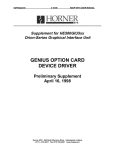
In summary, this is the execution order of any and all possible scripts:
Figure 1 Script Execution Flow Chart
Copyright 1997 Horner Electric, Inc.
All Rights Reserved
Page 10
Manual
GIU Editor Users
VARIABLES
Variables are important to any language, and especially so to the GIU Editor.
The normal usage of variables is still present -- to provide for storage of intermediate results from any
programming code used by the system. There are eleven (11) eleven types of variables available to the
GIU programmer, ranging from single bit (Boolean) to Long Doubles (64-bit floating point) to Variants
(variables which change their type according to the type of data put in them).
Variables are assigned in one of several ways. They may be defined locally within a script, or globally
before any scripts are written.
In the GIU, though, variables also provide the "gateway" to the hardware I/O system supplied by the end
user. Any variable may be "attached" to a physical I/O point of a suitable type. Then, any access to this
variable will cause an action such that the I/O points is read or written.
Copyright 1997 Horner Electric, Inc.
All Rights Reserved
GIU
Page 11
Editor
Users
Manual
OPERATIONAL ORDER
The specific order of operations is not normally important to the End User. However, the Programmer
may find this information of value.
After the GIU receives a power up RESET, or receives a RESTART PROGRAM command from either
the serial port or from the front panel keypad, the following sequence is followed:
1)
2)
3)
4)
Initialization of the system proper
Initialization of all Global variables
Execute the Initialization Script
Service the I/O
This does not actually perform physical I/O through any attached network.
Rather, any incoming information read copied from the Device Driver into any “read”
variables, and any “write” variables are copied into the Device Driver.
The Device Driver actually determines when the physical update takes place.
5) Execute the Control Script
6) If necessary, change the Visible Page Number
7) Execute the Page Script
8) Execute any Object Scripts assigned to this page
9) Update visual changes to Objects, if necessary
10) Execute the Alarm Script
11) Loop to Step #4
Steps 4 through 11 are known as The Control Loop.
Note that the Initialization Script is performed before the first I/O update service. This has some
implications when the GIU is used as a visual monitor attached to a PLC. In this case, most installations
will NOT want the GIU to write new values to the PLC during the GIU’s Initialization Phase. Because of
this a special feature has been added to the I/O Variable Association dialog (see Page 43).
In other installations the GIU may have sufficient power to be the Main Controller in the system. In this
case initialization of attached hardware values may be handled completely by the GIU.
FUNCTION KEYS
Function Key Scripts are handled asynchronously with the above sequence. Function Key Scripts are
executed immediately, as soon as their associated key press is detected.
It is impossible to determine exactly when a key will be pressed, with relationship to the overall
operational loop. This is because The User must press the Function Keys. Because of this, you must be
aware of how other scripts might interact with the Function Key Script.
Copyright 1997 Horner Electric, Inc.
All Rights Reserved
Page 12
Manual
GIU Editor Users
The best method for handling Function Keys is to avoid complicated logic functions within the Function
Key Script. Instead, provide a Global Variable (usually Boolean) that is set by the Function Key. Examine
this variable in the Control Script, and perform the necessary actions. This method will guarantee that the
desired action is performed at a known time with respect to the loop, regardless as to when The User
actually presses the key.
SHOWPAGE
The ShowPage command (page 97) is the statement used to switch between displayable pages. Its
effects on a running program are … "interesting".
First, understand that the actual "page switch" takes place ONLY in Step #6, above. Any request for a
ShowPage is "queued" until Step #6. However, ShowPage 's "queue" is only one layer deep. That is,
the most recently executed ShowPage will take precedence.
For example, if from within the Control or Alarm Script you code:
.
.
ShowPage 1
.
.
ShowPage 3
.
.
ShowPage 5
What will actually be seen on the display is Page 5.
The ShowPage effects when used from within a Page or Object Script are much different. ShowPage,
when used within a Page or Object Script, causes an immediate EXIT from the script. Therefore, if from
within an Object or Page script you code:
.
.
ShowPage 3
(subsequent code not executed)
.
.
ShowPage 5
All instructions after the ShowPage 3 will not be executed. In fact, if the ShowPage is executed from
within an Object Script, any subsequent Object scripts will not be executed.
Copyright 1997 Horner Electric, Inc.
All Rights Reserved
GIU
Page 13
Editor
Users
Manual
If the ShowPage is executed from within a Function Key script, operation can really get strange!
1) If a Function Key is pressed during any script, the script will run to completion.
2) If the Function key is pressed during an Object Script, the Object Script will run to
completion. But the Page on which the Object is present will be exited as soon as the effected
Object Script is complete.
NOTE: From within a Function key Script, the ShowPage command is issued by the
Goto Home Page or Goto Page commands.
The interactions here can be very subtle:
1) If a Function Key interrupts any given script, and the script subsequently executes a
ShowPage, the Script's ShowPage will override the Function Key ShowPage.
2) If a Function Key interrupts an Object Script, any subsequent Object Scripts will not be
executed.
The visible effects of the above can be variables that do not get set (or get set to the wrong value) pages
that do not get displayed, or Functions keys that need to be pressed twice (or more), or seem to not
function at all.
It would almost appear that using the ShowPage statement from within a Function Key should be
avoided. This is not the case, though, and using ShowPage from within any script is valid, expected, and
normal.
If you experience symptoms that you believe might be caused by the above, try using a different method
to switch pages. Consider that the problems can be caused by asynchronous events (Function Key
presses) that occur at inopportune times. To better control this situation, use the function key to set a
Global Variable (usually a Boolean) to some value, then examine this variable from with the Control
Script:
Global Declaration
Boolean Key_1,Key_2
Function Key F1 Script
Key_1 = TRUE
Function Key F2 Script
Key_2 = TRUE
Control Script:
If Key_1 = TRUE then
Key_1 = FALSE
ShowPage 1
Endif
If Key_2 = TRUE then
Key_2 = FALSE
ShowPage 2
Endif
Copyright 1997 Horner Electric, Inc.
All Rights Reserved
Page 14
Manual
GIU Editor Users
THE I/O SCAN
The I/O SCAN is the action necessary to move data between the Device Driver and the global variables.
There are two “tables” used for this operation: The Global Variables, and the “Data Table” inside the
Device Driver. Your program (all scripts, either User written or generated by the Wizard) reads data
from or writes data to the variables. The Device Driver takes data from it’s local table and writes it to the
attached physical I/O, or reads the physical I/O and places the data in it’s local data table.
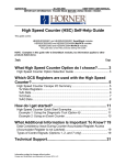
The I/O SCAN (Step 4, Page 11) is the section of code that actually transfers data between your program
and the Device Driver. This would appears something like this:
Figure 2 Your Program, The I/O Scan, and the Device Driver
There are two important points to notice here:
1) The I/O SCAN is normally done only once per Control Loop. The timing of the
Control Loop is determined by the size of the Control, Alarm, and Page Scripts, the
number and type of Objects being displayed, and if and when a Function Key is
pressed. Depending on the above, the time between I/O SCANS can ranges from a
few milliseconds to several seconds.
2) The Device Driver runs asynchronously to your program and the Control Loop. It is
not possible to control this timing from within your program.
To help insure “instantaneous” updates, the SERVICEIO (See Page 102) command is included. This
command forces the I/O SCAN to occur, thus updating the Device Driver’s Data Tables immediately.
This command will most often be found in Function Key Script. By forcing an immediate update of the
Device Driver’s Data tables the GIU can be used as a Push Button Replacement Device.
However, because of #2, above, we can not actually guarantee the physical hardware will be updated
“instantly”. The SERVICEIO command only transfers the data between the variables and the Data tables.
It does not (and can not) cause a physical scan of the I/O network.
Copyright 1997 Horner Electric, Inc.
All Rights Reserved
GIU
Page 15
Editor
Users
Manual
The actual physical scan of the I/O devices is timed by the Device Driver. This timing is set when the
Device Driver is configured (See Page 38). Thus, even though the SERVICEIO command is used, the
physical I/O will get updated only at the next scan of the network, as defined by the Device Driver.
NOTE: In Release 1 of the GIU Executor Firmware, the Device Drivers do not honor the
TIME setting of the Device Driver setup. All Device Drivers run at their fastest
possible speed.
Copyright 1997 Horner Electric, Inc.
All Rights Reserved
Page 16
Manual
GIU Editor Users
THE MENUING SYSTEM
THE MAIN MENU
All features of The Editor may be accessed through this menu and it's associated sub-menus.
Figure 3 The Main Menu
THE FILES SUB-MENU
The File Options are used in the standard Windows manner -- New, Open, Save, and Save As. The
options serve the purpose that a Windows user would expect.
Figure 4 The File Sub Menu
Copyright 1997 Horner Electric, Inc.
All Rights Reserved
GIU
Page 17
Editor
Users
Manual
NEW PROJECT
NEW PROJECT creates a new project workspace. All screens, objects, function keys, and scripts
are cleared. Page 0, which has been cleared, is displayed.
TIP: If the Toolbar is active, you may start a new project using the
Button.
Toolbar
OPEN PROJECT
OPEN opens an existing project workspace. The Editor looks in the current working directory for
files with the extension .GIU. You are presented with the standard Windows File Open
dialog, so selecting projects from other directories should be second nature to you.
TIP: If the Toolbar is active, you may open an existing project using the
Toolbar Button.
SAVE PROJECT
SAVE PROJECT writes the current project workspace to disk. For the SAVE to be truly
automatic, the project must have been "named" by first using the Save Project As option.
If the project is "unnamed" the SAVE option will automatically revert to the Save Project
As option.
Toolbar
TIP: If the Toolbar is active, you may save a project using the
button. If the project is previously unsaved, this option will automatically
revert to Save As.
SAVE PROJECT AS
SAVE PROJECT AS allows a project to be saved under a User-specified name.
In the case of a new project, it is necessary to use Save Project As to add a "name" to the
project. A project must be "named" in this manner before the Save option is functional.
SAVE RUNTIME BINARY
This option allows the project to be saved as a binary file, identical in format to that which is sent
to the GIU using the Target|Write Program menu option.
This file could be used for possible stand-alone file loaders. Stand-alone file loaders are, however,
not yet available.
Copyright 1997 Horner Electric, Inc.
All Rights Reserved
Page 18
Manual
GIU Editor Users
PAGE SETUP
This option allows you to define the page size and margin parameters of paper you are using.
PRINT
This option allow you to print (make a hard copy) of your program. You have the option to print
all or part of the program, including screens, scripts, and I/O definitions.
TIP: If the Toolbar is active, you may print a project using the
Button.
Toolbar
EXIT
EXIT causes The Editor to terminate.
MOST RECENTLY USED LIST
Between the PRINT and EXIT options there will appear a Most Recently Used list. This list will
contain the eight (8) most recently accessed file paths.
Copyright 1997 Horner Electric, Inc.
All Rights Reserved
GIU
Page 19
Editor
Users
Manual
THE EDIT SUB-MENU
The Edit Options allow access to Page-oriented editing features. Objects are first selected Objects that
have been selected may be CUT, COPIED, PASTED, or DELETED.
Figure 5 The Edit Sub-Menu
UNDO
The UNDO command is not presently functional. It is included here for compatibility with future
releases of The Editor.
CUT
The selected object(s) is first moved to the Clipboard, then deleted from the page. Any item thus
moved may be recalled later using the PASTE command.
TIP: If the Toolbar is active, use the
command.
Toolbar Button to perform the CUT
COPY
The selected object(s) is moved to the Clipboard, and remains on the page. Any item thus moved
may be recalled later using the PASTE command.
TIP: If the Toolbar is active, use the
command.
Toolbar Button to perform the COPY
PASTE
Any object(s) on the Clipboard are placed on the selected page. Their position on the screen is
retained.
TIP: If the Toolbar is active, use the
command.
Toolbar Button to perform the PASTE
Copyright 1997 Horner Electric, Inc.
All Rights Reserved
Page 20
Manual
GIU Editor Users
DELETE
The selected object(s) is deleted. Such objects may not be recalled for later use.
SELECT ALL
All visible objects on the page are selected to be CUT, COPIED, or DELETED.
THE PROJECT SUB-MENU
The Project Options allows you to define certain items that will be used on a program-wide basis:
Figure 6 The Project Sub Menu
VARIABLES
Select this menu item to define Variables. Variables may also be "attached" to external hardware
through one of the networks available to the GIU hardware.
BITMAPS
Select this menu item to assign Tag Names to any bitmapped files that you may be using.
Bitmapped files may be used as wallpaper on a GIU Screen designated as "graphical".
KEYS
Select this menu item to program the available Function Keys (to the left, right, and below the
display screen) on a project level (global) basis.
NOTE: Project Level (global) Function Keys are superseded Page Level Function
Keys.
Copyright 1997 Horner Electric, Inc.
All Rights Reserved
GIU
Page 21
Editor
Users
Manual
GLOBAL DECLARATIONS
Select this menu item to declare global (project level) variables and functions
INITIAL SCRIPT
Select this menu item to create or edit the program's Initialization Script
CONTROL SCRIPT
Select this Menu Item to create or edit the program's Main Control Script.
ALARM SCRIPT
Select this menu item to create or edit the program's Alarm Script.
DEVICE DRIVERS
Select this menu item to add or delete Device Drivers. During this process you will also be
allowed to "attach" different or multiple I/O devices to a single network (if that is supported by
the network), and to "attach" specific I/O points to system variables. Thus, a program variable
may be assigned to a specific I/O point on a specific device on a specific network.
GIU MODEL
This item is included to allow compatibility with future products in the GIU line.
DEFAULT DISPLAY COLOR
This item is included to allow compatibility with future products in the GIU line. It is currently
disabled.
HOME PAGE NUMBER/NAME
This item is included to allow compatibility with future products in the GIU line. It is currently
disabled.
CHECK FOR ERRORS
Select this menu item to verify that any program you write is free from errors. Any errors are
reported to you in the Error Box. You must correct them before downloading a program to a
GIU.
TIP: If the Toolbar is active, use the
Toolbar Button to check for errors.
VIEW ERROR BOX
This option will cause the Error Box to be displayed. Use this option to review the Error Box if it
is not currently displayed.
TIP: If the Toolbar is active, use the
Toolbar Button to recall the Error Box.
Copyright 1997 Horner Electric, Inc.
All Rights Reserved
Page 22
Manual
GIU Editor Users
THE PAGE SUB-MENU
Figure 7 The Page Sub Menu
The Page Options allows you to define or select various items that are active on a per-page basis
PROPERTIES
Select this menu item to determine the properties of the page: graphical or textual, annunciator
beep, caption, and associated bitmap.
FUNCTION KEYS
Select this menu item to program the available Function Keys (to the left, right, and below the
display screen) on a per-screen basis.
NOTE: Page Level (local) Function Keys supersede Project Level (global)
Function Keys.
SCRIPT
Select this menu item to create or edit a script for this page.
OBJECT ORDER
Select this menu item to view the object numbers assigned to any objects on the page. This
information is useful for debugging.
COPY FROM PAGE
Select this function to copy the entire contents of any page to the currently displayed page. This is
useful when a project requires multiple pages with are identical with only minor exceptions. Using
this option the entire contents of the selected page are copied -- objects, scripts, and function
keys.
DELETE ALL CONTENTS
Select this option to completely clear a page. All contents are "wiped" -- object, scripts, and
function keys.
Copyright 1997 Horner Electric, Inc.
All Rights Reserved
GIU
Page 23
Editor
Users
Manual
GOTO PAGE
This option allows you to select which “page” will be displayed in the selected window
TIP: If the Toolbar is active, use the
command.
Toolbar Button to issue the Goto Page
PREVIOUS PAGE
The Editor keeps a Most Recently Used list for each currently visible window. Use PREVIOUS
PAGE to select the previously viewed page in the selected window.
TIP: If the Toolbar is active, use the
page.
Toolbar Button to select the previous
NEXT PAGE
The Editor keeps a Most Recently Used list for each currently visible window. Use NEXT PAGE
to select the next page in the selected window.
TIP: If the Toolbar is active, use the
Toolbar Button to select the next page.
Copyright 1997 Horner Electric, Inc.
All Rights Reserved
Page 24
Manual
GIU Editor Users
THE OBJECT SUB-MENU
Figure 8 The Object Sub Menu
These options allow you to select and manipulate objects on the displayed page.
NOTE: There is a limit of 256 Objects per page.
WIZARD
Selecting this option brings up the Object Wizard. The Object Wizard allows variables to be
attached to objects, allows the object to be "ranged", and allows the attached variable to
manipulate certain object-dependent features (for example, color).
SCRIPT
Selecting this option to create or edit the script associated with the selected object.
ALIGN OBJECTS
Selecting this option allows multiple objects to be aligned with each other on a top, bottom, left,
or right side manner. This allows you to easily create more pleasing displays.
Selecting this item will cause a popup menu to appear, giving you the available choices: Top,
Bottom, Left, Right.
,
,
, or
Toolbar Buttons to
TIP: If the Toolbar is active, use the
Align Left, Align Right, Align Bottom, or Align Top, respectively.
MAKE SAME SIZE
Selecting this object will force all selected objects to the same size. This allows you to easily
create more pleasing displays.
Selecting this item will cause a popup menu to appear, giving you the available choices, Vertical,
Horizontal, or Both.
,
, or
Toolbar Buttons to Make
TIP: If the Toolbar is active, use the
Same Size Vertical, Make Same Size Horizontal, or Make Same Size Both,
respectively.
Copyright 1997 Horner Electric, Inc.
All Rights Reserved
GIU
Page 25
Editor
Users
Manual
THE TARGET SUB-MENU
Figure 9 The Target Sub Menu
These options allow you to select, deselect, and manipulate an attached GIU device.
CONNECT
Selecting this option will cause The Editor to establish the connection between The Editor and a
pre-defined GIU device (see GIU TAG NAMES below).
TIP: If the Toolbar is active you may CONNECT using the
Toolbar button.
DISCONNECT
Selecting this item will cause The Editor to release the connection between The Editor and the
attached GIU Device
TIP: If the Toolbar is active you may DISCONNECT using the
Toolbar button.
GIU TAG NAMES
This option allows you to add, edit, or remove a GIU Tag Name. This tag will be associated with
a particular unit having User-defined properties such as communications port, baud rate, etc. The
Tag Name is used in the CONNECT function, above.
NOTE: If the Disconnect menu item is enabled, this item will be disabled
(grayed).
Copyright 1997 Horner Electric, Inc.
All Rights Reserved
Page 26
Manual
GIU Editor Users
READ PROGRAM
Selecting this option allows you to upload a program from an attached GIU device into The
Editor.
NOTE: The program must have been written using the ATTACH SOURCE
CODE TO WRITES command, below.
TIP: If the Toolbar is active you may READ PROGRAM using the
button.
Toolbar
WRITE PROGRAM
Selecting this option allows you to download a program from The Editor into an attached GIU
device. The program is first checked for errors in a manner identical to the Project|Check
for Errors menu item. If the program is sizable, this could take several seconds.
TIP: If the Toolbar is active you may WRITE PROGRAM using the
button.
Toolbar
VERIFY PROGRAM
Selecting this option causes The Editor to read a program from the GIU, and perform a
comparison between it and the one in The Editor's memory.
DELETE PROGRAM
Selecting this option causes The Editor to delete any program in the GIU.
STATUS
Selecting this option allows you to check on the operational status of an attached GIU device.
Reported are the GIU firmware revision level, the loaded program's name and size, and the
currently displayed page.
TIP: If the Toolbar is active you may get PROGRAM STATUS using the
Toolbar button.
RESTART PROGRAM
Selecting this option will cause The Editor to send a RESTART command to the GIU device. This
is similar in action to unplugging the power from the GIU. The currently running program will be
terminated, the GIU will be reset, and any loaded program will be restarted.
TIP: If the Toolbar is active you may RESTART using the
Copyright 1997 Horner Electric, Inc.
All Rights Reserved
Toolbar button.
GIU
Page 27
Editor
Users
Manual
SUSPEND PROGRAM
This option causes any program running in the GIU to stop, but retaining the all information such
that the program can be restarted exactly where it left off.
RESUME PROGRAM
This option causes a previously suspended program to resume operation. Note that this command
can not be used on a program that has been terminated, or just downloaded to the GIU.
TERMINATE PROGRAM
This option causes any program running in the GIU to be terminated. Any network controls are
stopped; all information is lost.
TIP: If the Toolbar is active you may TERMINATE PROGRAM using the
Toolbar button.
INSPECT MEMORY
Selecting this option allows you to inspect certain memory locations inside the GIU.
AUTO-RESTART AFTER WRITE
This selection is a "switch". When ON (the item in the menu is checked) The Editor will issue a
RESTART command after a program is downloaded. If the switch is OFF (the menu item is not
checked) then the GIU will require that you manually issue the RESTART command.
AUTO-CONNECT TO LAST TARGET
This selection is a “switch”. When ON (the item in the menu is checked) The Editor will
automatically re-connect to the unit that it was connected to when The Editor was last exited.
Since most Users will be working with one unit, this can be quite convenient.
ATTACH SOURCE CODE TO WRITES
This selection forces The Editor to include Source Code when it downloads a program. This is
useful, because a subsequent User can upload the file, including source code, for editing or
examination. Refer to the READ PROGRAM command, above.
Copyright 1997 Horner Electric, Inc.
All Rights Reserved
Page 28
Manual
GIU Editor Users
THE OPTIONS SUB-MENU
Figure 10 The Options Sub-Menu
This allows you to select certain features that determine how The Editor appears or acts, but these
features have no direct effect on the GIU code generated.
TEXT BORDERS
The Text Objects have no inherent method to allow you to determine the limits of the object.
During certain operation you may want to know exactly the boundaries of the Text Object, either
to align the objects, or to avoid placing one object "on top of" another.
a dashed line will be used to indicate the extent of Text
With the Text Borders option checked
Objects. The dashed lines, however, can clutter the display. Mark the Text Borders unchecked
to remove the dashed lines
GENERATE .STK ON COMPILE
This is a switch that, when checked
file.
, will cause the compiler to generate a BASIC diagnostic
This file has no immediate use to you, the programmer. This switch should be unchecked
all normal operation of The Editor.
for
NOTE: Leaving this option checked could cause serious degradation of The
Editor's performance, especially with large programs.
This option is included for the future possibility that you may need to contact Horner Electric
Technical Support. Technical Support personnel may ask you to check this option, compile the
program, then read certain information from this file.
Copyright 1997 Horner Electric, Inc.
All Rights Reserved
GIU
Page 29
Editor
Users
Manual
THE TOOLS SUB-MENU
Figure 11 The Tools Menu
REGENERATE SCRIPTS FROM WIZARDS
This option allows you to "repair" scripts written using previous version of The Editor, which
may not be fully compatible with the current version.
NOTE: Only scripts written using wizards will be repaired. Scripts created in the
"manual edit" mode will require manual editing.
WRITE GIU FIRMWARE
Selecting this option allow you to update the graphical "executor" firmware on-board the GIU.
This is different from the "BIOS", which is loaded in a separate step, using a DOS-based loader.
Copyright 1997 Horner Electric, Inc.
All Rights Reserved
Page 30
Manual
GIU Editor Users
THE WINDOW SUB-MENU
Figure 12 The Window Sub-Menu
Selecting these options allows you to select a new or previously assigned "page" in the program, to "tile"
and displayed pages, or to select for display the Toolbar or Status Bar.
NEW WINDOW
This option opens a new window in the display area. You will be asked to select a GIU Page to be
displayed in this window.
Any window may display any page, and multiple windows may display the same page.
TILE HORIZONTALLY
Selecting this option will cause all windows to be displayed in a horizontal manner.
TILE VERTICALLY
Selecting this option will cause all windows to be displayed in a vertical manner.
CASCADE
Selecting this option will cause all windows to be displayed in a cascading manner.
CLOSE ALL
Selecting this option will close all open windows.
TOOLBAR
This option is a switch to activate or de-activate the TOOLBAR that runs along the TOP of the
display.
STATUS BAR
This option is a switch to activate or de-activate the STATUS BAR that runs at the bottom of the
display.
Copyright 1997 Horner Electric, Inc.
All Rights Reserved
GIU
Page 31
Editor
Users
Manual
VISIBLE WINDOW LIST
This selection allows you to select ONE of the windows that are currently loaded. The Page
Number and Page Name displayed in up to nine (9) windows may be displayed. If more than nine
windows are available, you have the option to select the desired window from a sub-menu.
Copyright 1997 Horner Electric, Inc.
All Rights Reserved
Page 32
Manual
GIU Editor Users
USING THE EDITOR
INVOCATION
Double-click the icon for the GIU editor. The Editor will begin execution.
A SIMPLE OVERVIEW
A block diagram will be helpful to describe different parts of a GIU program and their interactions:
Figure 13 The Editor Flow Chart
The basic unit of storage is the PROJECT. The project contains all parts of the program. When a Project
is opened, these parts become accessible. When a Project is closed, any changes made are saved.
Copyright 1997 Horner Electric, Inc.
All Rights Reserved
GIU
Page 33
Editor
Users
Manual
The basic parts of a User Program are Pages, Objects, Scripts, and Variables.
PAGES are primarily used to describe the screen that is to be visible on the GIU. You may consider
PAGES and SCREENS to be synonymous, but a screen is actually only one of the functions of a page.
Pages may also contain scripts, function keys, and objects, and variables may be accessed from the page's
objects, scripts, and function keys. It may be more correct to consider a page as a major subroutine called
at the appropriate times from a major control program.
OBJECTS are the visible "items" displayed by the page. Typical of object oriented systems, OBJECTS
are merely symbols representing more complex sections of code. An object may be used to read or write
data from an attached PLC, or may perform some other task like updating or changing a variable.
NOTE: There is a limit of 256 Objects per page.
Objects often have ATTRIBUTES. Some attributes may be changed only by the programmer, using The
Editor. Such attributes would be the physical size and position of the object on the screen. Other
attributes may be changed under program control, at run time. These attributes might include the object’s
value, color, or other displayable characteristics (like text).
SCRIPTS are User-defined sections of code that are executed at appropriate times. Scripts may be
"globally" defined on a project-wide basis, or "locally" defined on a per-page basis. You may write or
customize these scripts to perform specific actions.
There are three (3) "global" scripts: Initialization, Control, and Alarm. The Initialization Script is called
only once, when the program first executes. In here, you may initialize certain variables, or perform other
tasks that must be performed before the main program operates.
The Control Script is the "main" program. Normally, User-written Control Scripts are not necessary, as
the simple act of creating a Screen of Objects is sufficient to produce all necessary control. However, the
Control Script is available for those Users that need more or specific control functions.
The Alarm Script is logical grouping of GIU BASIC code. Although the GIU actually executes the Alarm
Script during every pass, the code herein is designed to be used only during alarm situations. With the
proper use of project-wide (global) variables as "flags", you can trap and control the systems Alarm
response.
Page Scripts are executed only when the associated page is displayed. Since you also have control over
when a page is displayed, you thus have control over when these scripts are executed.
NOTE: Objects also have scripts, but access to these scripts is normally through the
Object Wizard. The Object Wizard will automatically create Object Scripts.
Copyright 1997 Horner Electric, Inc.
All Rights Reserved
Page 34
Manual
GIU Editor Users
VARIABLES are as expected -- They are used to hold temporary values operated on by the various
scripts. Variables may be GLOBAL (available to all parts of the program at all times) or LOCAL
(available only from within the script that defines them).
Variables are also the "gateway" to the Device Drivers. A variable may be attached to a specific I/O
device through the Device Driver. When this variable is accessed, this will causes appropriate activity by
the device driver to read or write the variable's values to or from the hardware device.
The attachment process is simple. You are concerned only with what device is accessed, not how it is
accessed. This level of isolation removes much of the drudgery of programming I/O.
CONNECTION TO THE GIU DEVICE
Once a program is constructed using The Editor, it is transmitted to the GIU device through a serial link.
This link uses a proprietary protocol called HECOM, designed specifically for this purpose.
NOTE: HECOM is NOT an I/O network. The Editor itself has no direct nor indirect
access to any I/O devices present in the system.
HECOM uses an RS232 serial link between the Host computer (running The Editor) and the GIU device.
A 9-pin "straight through" cable is all that is required.
You must "tag" a device. In doing so, you are asked to determine the Host PC's Comm Port and baud
rate. Once a unit is "tagged" you will not be asked for communications parameters for this tag.
The baud rate used to communicate to the GIU device is programmable. Other serial parameters (number
of bits, stop bits, etc.) are fixed by The Editor and the GIU, so you have no need for control of these
parameters.
INTERACTIONS BETWEEN THE EDITOR AND THE GIU DEVICE
Interaction between The Editor and the GIU Device are limited. Since the GIU Device is designed as a
stand-alone unit, there is no need for complicated interactions between The Editor and the GIU.
Interactions are limited to Program Reads and Writes, and Status.
The Editor compiles your program into a data table to be operated on by the GIU Device. This data table
contains the pages, objects, scripts, defined variables, and any possible attachments to I/O devices. Once
compiled, the data table is transmitted to the GIU device using the HECOM protocol.
Once the program is written to the GIU Device, you may only check the Device Status. This gives a
general indication of whether the device is running, and what actions it is performing.
You can not directly access nor effect a running GIU program except to stop, start, read, or write the
complete program. Neither can you access any points in attached I/O devices.
Copyright 1997 Horner Electric, Inc.
All Rights Reserved
GIU
Page 35
Editor
Users
Manual
WRITING A PROGRAM
In its simplest form, writing a program takes only 5 major steps:
1)
2)
3)
4)
5)
6)
Define and setup Device Drivers.
Define any variables.
Create new page(s) by placing objects on the page(s).
Set the object's properties, including associated variables.
Attach the variables to I/O points
Write the program to the GIU
In most cases, the first five steps may be taken in any order!
DEFINING AND SETTING UP DEVICE DRIVERS
All programs have two things in common: They need some kind of input to operate on, and they produce
some sort of useful output. One of the most important points of programming is to define where the input
comes from and where the outputs go. Further more, when the GIU is involved we need to sub-divide
inputs and outputs into two groups -- those intended for the GIU alone, and those intended for "real
world" I/O devices, such as attached PLCs.
Once the I/O is defined, we should let The Editor and GIU know about these points early in the program
design process. Primarily, this consists of defining and setting up the different Device Drivers available.
The following diagram shows how variables and Device Drivers interact:
Figure 14 Variable to I/O Association
NOTE: This diagram should not be used to infer any limits on the number of variables,
units, device drivers, nor the number or types of interconnections. There may,
however, be limits placed by the actual device driver or unit attached.
Copyright 1997 Horner Electric, Inc.
All Rights Reserved
Page 36
Manual
GIU Editor Users
A VARIABLE is a unit of storage defined by the GIU. Like any programming language, variables are
used to store results of previous calculation. In the GIU, though, a variable may also be "attached" to a
particular I/O point of a real hardware device. In this case, reads or writes of the variable will cause
similar actions to be performed on the hardware device.
A UNIT is a logical grouping of I/O points. A Unit directly correlates to a specific hardware device, for
example a single PLC. A Unit will contain information about the numbers and types of I/O points
available to the device, as well as other pertinent information like Device IDs, Node Addresses, access
passwords, etc.
A DEVICE DRIVER is the software that allows the GIU to communicate with the attached devices.
The Device Driver looks at the Unit definition to determine which device to "talk" to.
Defining I/O, then, is a matter of defining the different Units available, including their number and type of
I/O points, and which Device Driver they are attached to. The Device Driver itself may need definition in
terms of communications parameter (baud rates, etc.). Finally, certain program variables are "attached" to
the different I/O points available to a specific device.
ADDING A DEVICE DRIVER
From the Project sub-menu, select Device Drivers. In the resulting dialog, click
new dialog pops up:
Figure 15 Device Driver ADD Dialog Box
The following functions are available to Add a New Unit to a specific Device Driver.
Driver
Select the desired Device Driver from the available list.
Copyright 1997 Horner Electric, Inc.
All Rights Reserved
. A
GIU
Page 37
Editor
Users
Manual
Tag Name
Type in an identifying name (a "tag") to be assigned to this iteration of this driver. Under
certain circumstances, one Device Driver might be used to control 2 or more physical
networks. The Tag Name identifies the network used. There is a limit of 32 characters for
the Tag Name.
Expansion Slot
The GIU supports two Expansion Slots to support specialized hardware. Currently, no
devices are available to use these slots. Leave this entry at NONE.
Setup Summary
This box displays the current parameters for the selected device driver.
Setup
Once the desired Device Driver is selected, click the
button to set the Driver's
parameters. The appearance of the resulting dialog will depend on the driver selected.
EDITING OR REMOVING A DEVICE DRIVER
If the Driver has already been defined, it may be edited or removed. Select Project|Device
Drivers:
Figure 16 Device Driver Add/Remove Dialog Box
Highlight the desired Device Driver entry, then click either
or
to complete the desired
task. If
is selected, you will be brought into Device Driver dialog described above.
Copyright 1997 Horner Electric, Inc.
All Rights Reserved
Page 38
Manual
GIU Editor Users
SETTING UP THE DEVICE DRIVER
Setting up the Device Driver is peculiar to each different device. Once the Device Driver is selected, as
above, refer to the Device Driver specific instructions given in the Appendices to this manual.
Setup for each individual device will be peculiar to that device. Therefore, setting up of the Device Driver
is described in a separate Appendix to the manual for each Device Driver included. Refer to the specific
Appendix for the Device Driver you wish to set up.
DEFINING (ADDING) VARIABLES
Good programming practice dictates that variables should be defined and created first, when possible.
This helps prevent memory size "creep" that often occurs when programs are written "on the fly",
without some forethought as to their use and operation. However, The Editor allows variables to be
defined at any time, up to the time that a program is downloaded to an attached GIU.
When The Editor is first invoked, you are presented with a blank "page". For the time being, ignore the
Page display.
TIP: If all pages are not blank, or you need to start over, or you just want to be sure, click
on File/New to start over.
From the Main Menu, select Project/Variables. This will bring up a Dialog Box. The Dialog Box
should be empty, since at this point no variables have been added.
Copyright 1997 Horner Electric, Inc.
All Rights Reserved
GIU
Page 39
Click
Editor
Users
Manual
to add a new variable. This will bring up the Variable Addition dialog:
Figure 17 Variable Add Dialog Box
The functions of this box are reasonably obvious.
Name
This is the variable's NAME, or "tag name", by which it will be accessed by the rest of the
program. Variable names may be up to 32 characters in length. Only alphanumeric characters are
acceptable, upper or lower case, and the '$' character.
Exported
This feature is for future enhancements. For now, leave it unchecked
Copyright 1997 Horner Electric, Inc.
All Rights Reserved
.
Page 40
Manual
GIU Editor Users
Type
This is the type of variable. Possible types are :
TYPE
Boolean
Char
Byte
Integer
Word
Long
Dword
Float
Double
String
Variant
SIGN
N/A
signed
unsigned
signed
unsigned
signed
unsigned
signed
signed
N/A
SIZE
1 bit*
1 byte
1 byte
2 bytes
2 bytes
4 bytes
4 bytes
4 bytes
8 bytes
variable
RANGE
0 or 1
-128 to +127
0 to 255
-32768 to +32767
0 to 65535
-2147483648 to +2147483647
0 to 4294967295
-3.402823e+038 to +3.402823e+038
-1.797693e308 to +1.797693e308
user defined
Varies according to type
* In the case of ARRAYS, however, Boolean variables take 1 bit, rounded to the next byte. Therefore, an array of 2
Boolean variables take 1 byte, an array of 3 Boolean variables takes 1 byte…. An array of 8 Boolean variables take 1
bytes, an array of 9 Boolean variables take 2 bytes, etc.
Array / Elements
Click on Array to signify this variable as an array of variables of the specified TYPE. Enter a
numeric value into the Elements box to specify the number of elements in the array. The required
storage is then ELEMENTS * SIZE.
GIU BASIC arrays are “0”-based. For an array of “n” elements, the elements are:
element(0)
element(1)
.
.
element(n-1)
Scaling
This section allows a variable to be scaled between actual "raw" I/O values an "engineering units"
(EU), which is a User-defined range of values.
To use Scaling, click the Enabled Box
boxes are available.
. With Scaling enabled, the SLOPE and BIAS
NOTE: Variables are scaled when they are assigned (written), but not when they are
referenced (read). If ‘X’ is a scaled variable, then
X = RAW_TEMP
will cause a scaling action, but
RAW_TEMP = X
will not.
Copyright 1997 Horner Electric, Inc.
All Rights Reserved
GIU
Page 41
Editor
Users
Manual
DEFINING (ADDING) VARIABLES: A PRACTICAL EXAMPLE
Here is a more real-life example of adding and defining a variable.
The situation is that a certain thermocouple device is used to read -200 °C to +200 °C. The thermocouple
input card generates a 12-bit (0 - 4095) conversion. The card is adjusted such that -200 °C converts to 0
and +200 °C converts to 4095.
From the Main Menu, select Project/Variables. In the Variable Dialog Box set the NAME to
"Temp1", set the TYPE to "SHORT", and enable the SCALING feature.
Scaling will be used to convert the "raw" reading of 0 to 4095 to 'engineering units" (EU) in Degrees
Celsius. Scaling uses the following formula:
EU = (V *
Where: EU
V
S
B
S) + B
= Engineering Units
= Raw Input Value
= Slope
= Bias (offset)
Using the above temperature input as an example, we'll work out this equation to derive suitable values
for SLOPE and BIAS to be input into the Variable Dialog Box.
First, declare the range of values acceptable for EU and the Input value:
EU_Minus
EU_Plus
EUs
-200
+200
Input Value (V)
0
4095
Next, use these figures to determine the SLOPE value:
SLOPE = (EU_Plus - EU_Minus) / (V_Plus - V_Minus + 1)
BIAS is chosen experimentally to "move" the final result in the proper direction, as indicated below.
To check these values, plug in some expected input values, and see if they provided the expected
Engineering Units.
TEST 1: Input: 4095 Expected EU: +200
EU = (SLOPE * INPUT) + BIAS
EU = (.0976 * 4095) + (-200)
EU = 399.672 + (-200)
EU = 199.672
TEST 2: Input: 0 Expected EU: -200
EU = (SLOPE * INPUT) + BIAS
EU = (.0976 * 0) + (-200)
EU = 0 + (-200)
EU = -200
TEST 3: Input: 2048 Expected EU: 0
EU = (SLOPE * INPUT) + BIAS
EU = (.0976 * 2048) + (-200)
EU = 199.884 + (-200)
EU = 0.115
TEST 4: Input: 2047 Expected EU: 0
EU = (SLOPE * INPUT) + BIAS
EU = (.0976 * 2047) + (-200)
EU = 199.7872 + (-200)
EU = -0.2128
Copyright 1997 Horner Electric, Inc.
All Rights Reserved
Page 42
Manual
GIU Editor Users
We have therefore determined that the proper value for Slope is 0.0976, and the proper value for Bias
is -200.
It might appear that there is an error here, in that 0.00 volts isn't recovered. A description of analog-todigital conversion theory is outside the scope of this manual. Suffice it to say that these "errors" are in the
conversion process used, and do not indicate an error in either The Editor software or the GIU. In fact,
these are not really "errors" at all!
Once the name, type, and scaling of the variable is determined, it may be "attached" to a physical I/O
location, in this case the values coming from the thermocouple input card.
ASSOCIATING VARIABLES TO I/O POINTS
Many variables used values obtained from the I/O devices through an industrial network connected to the
GIU. The Editor allows direct "attachment" of I/O points to any program variable of a suitable type
(generally INTEGER or BOOLEAN).
The idea to cause a logical "attachment" between a pre-defined variable and a pre-defined I/O point,
which exists somewhere on one PLC connected to one of one of [possibly] several industrial networks.
Variable are associated with I/O points through the Device Driver dialogs. Follow these steps:
1) From the Main Menu, Select Project|Device Drivers.
2) Double Click on the Device Driver on which the desired I/O point(s) are connected.
3) Click on
4) Follow the sequence as prescribed for the selected Device Driver to "attach" a variable to an
I/O point.
After the above sequence is done, the following dialog should appear:
Figure 18 Variable to I/O Association Box
Click on the
button to drop down the list of previously defined variables, then double click the
variable to be associated with this I/O point.
TIP: You can define a NEW variable at this time by clicking the
Copyright 1997 Horner Electric, Inc.
All Rights Reserved
button.
GIU
Page 43
Editor
Users
Manual
Read
This variable can be read through the associated Device Driver. This is the default setting.
Although it can be turned off (the variable can not be read), this would seem to have little use.
Write
This variable can be written through the associated Device Driver. If you write to the variable
from within your program, that value will be passed to the attached hardware through the Device
Driver.
NOTE: Read and Write can be set independent of each other.
Suppress Initial Write, If Zero
All variables are cleared (set to zero) when the GIU is reset, or the RESTART command is
received. If the variable is marked as Write, the zero value will also be written to the attached
hardware.
this box to disable the
Under certain circumstances this action may not be desirable. Check
writing of initialization zeros. Writing of this variable through the Device Driver will begin with
the first non-zero value written to this variable by your program.
If you desire to initialize this variable to some value other than zero do so from within the
Initialization Script.
If you wish to initialize the hardware to a value of zero, uncheck
this box.
Unscale On Write
When the variable was first created, you had the option of SCALING the variable. [See Defining
Variables - Scaling on Page 40]. In the case of I/O, however, it is rare that the scaled value will
be written to the physical I/O. Usually, the “raw” value needs to be written. You may check
the UNSCALE ON WRITE box to insure that the variable’s “raw” value is written to the I/O.
When you have selected and configured the variable, click
. The GROUP dialog will be updated
with the results. Continue this procedure until you have associated all desired variable and I/O points.
"Back out" using
until you reach the Main Menu.
Copyright 1997 Horner Electric, Inc.
All Rights Reserved
Page 44
Manual
GIU Editor Users
CREATING PAGES
The PAGE is the basic organizational unit of the GIU. The visible objects are placed on the pages.
Certain keystrokes can be assigned to pages. Pages have special scripts that are run only when the page is
displayed.
When The Editor is first invoked, you are presented with an initial blank page - Page 0. The size of the
page is determined by the setting of the Project|GIU Model setting. This page represents a single
screen of the Target GIU.
To create a new page, select Window|New Window. From the resulting Dialog Box, select a suitable
empty page
NOTE: You may select new pages in any numeric order. It is not required that all pages
be selected or used numerically.
The newly selected page may overlap a previously selected page. Use the Window|Tile
Vertically or Window|Tile Horizontally selections to "clean up" the display.
SETTING PAGE PROPERTIES
One the page is selected, you may set or re-define its properties. From The Editor Main Menu, select the
Page|Properties option. This will bring up the following dialog:
Figure 19 Page Properties Dialog Box
Caption
The is the legend that is to appear in the Page's display window Title Bar.
Graphical
If checked , this signifies that this Page provides graphically oriented (rather than textual)
information. This is the default mode of operation.
Copyright 1997 Horner Electric, Inc.
All Rights Reserved
GIU
Page 45
Editor
Users
Some Pages may require text only output. In this case this box should be unchecked
produce a text-only page, similar to an MS-DOS™ text display.
Manual
. This will
Beep While Displayed
If checked
signifies that the GIU should beep, using its internal beeper, during the time this
page is displayed.
Show Page Number & Caption at Runtime
signifies that the Page Number and Caption are to be displayed on the GIU during
If checked
the time this page is displayed.
Bitmap
If a Page is defined as Graphical, then the Page may used a user-defined bitmap as background
"wallpaper". In this box, enter the TAG NAME of the desired bitmap. [See USING BITMAPS,
Page 63.]
Use the pull-down list to see all currently defined bitmaps.
COPYING A PAGE
If an existing page already contains all or most of the objects you need, you may copy from one page to
another. This can save considerable time, as opposed to recreating each page, object-by-object.
To copy a complete page from one page to another, follow these steps:
1) See that the DESTINATION page is active by clicking the mouse somewhere within
its displayed area. The title Bar of the window is a good place.
2) Select the Page|Copy from Page... item.
3) From the displayed list, select the SOURCE Page, the Page that you wish copied from.
All data will be copied form the SOURCE Page to the DESTINATION Page.
DELETE ALL CONTENTS FROM A PAGE
Deleting All Contents will do just that! All objects, variable, and scripts on the selected Page will be
deleted, leaving you with a "clean slate" on which to work. Note, however, that Deleting All Contents
can be potentially dangerous, as it does delete all contents.
To Delete All Contents of a page:
1) Select the Page by clicking the mouse somewhere within its displayed area. The title
Bar of the window is a good place.
2) Select the Page|Delete All Contents... item.
3) You will be asked to verify the ensuing delete. Select YES or NO.
Copyright 1997 Horner Electric, Inc.
All Rights Reserved
Page 46
Manual
GIU Editor Users
DEFINING FUNCTION KEYS
The GIU has sixteen (16) Function Keys available to the Operator. The Programmer may use any or all of
these keys.
Figure 20 GIU Function Key Placement
NOTE: The lettered keys are NOT the alphanumeric entry keys!
These keys may be made active by assigning a SCRIPT to them. Additionally, any key may be active at
either the Project level or at the Page level. A key that is active will perform its script when the key is
pressed
NOTE: If any key is assigned at both the Project and Page level, the Page level function
key will take precedence.
To assign a key, first determine at what level, Project or Page, the key is to function. Select this level
from The Editor's Main Menu, Project or Page.
TIP: A key may be assigned to both Page and Project levels.
Copyright 1997 Horner Electric, Inc.
All Rights Reserved
GIU
Page 47
Editor
Users
Manual
From the resulting menu, select Function Keys… to bring up the following dialog:
Figure 21 Global Function Key Programming Dialog Box
This dialog indicates Global Function Keys. The Page Function Keys
dialog is identical in function.
If the script is empty, the Edit, Remove, Move Up, and Move Down buttons are disabled.
SELECTING A FUNCTION KEY
First, select the Function Key to be edited using the Key box. Use the
list of available keys.
button to view the complete
NOTE: The this list may contain more keys than are available on the unit you are using.
The extra keys are included for future expansion capabilities.
Key names which are display with an asterisk (*) have already been assigned. Selecting one of these keys
will allow you to edit the key script.
When the desired key is selected, any available script will be presented in the Commands window. For
the present assume that the key selected has no previously written script.
Copyright 1997 Horner Electric, Inc.
All Rights Reserved
Page 48
Manual
GIU Editor Users
ADDING COMMANDS TO THE KEY'S SCRIPT
When an active Function Key is pressed, its associated script will be performed. A script may be as simple
a list of commands to be performed, or may be as complex as a User-written GIU BASIC program.
The easiest way to write a script is to add pre-defined commands. Make sure the Manual Script Editing
box is UNCHECKED . At the bottom of the dialog you will find the Command Entry Box:
This box allows you to select pre-defined commands. Use the
commands:
COMMAND
Goto Page
Set Variable to Fixed Value
Momentary Value Assignment
Prompt User for Variable Value
Message Box
Manual Statement
Goto Home Page
Previously-Viewed Page
Prompt Goto Page
Service I/O Table
to select from the list of available
EDITABLE
YES
YES
YES
YES
YES
YES
NO
NO
NO
NO
Select a pre-defined command from this list by highlighting it, then clicking on the
command will be inserted into the script.
button. The
The selected command is always inserted before the highlighted line. If multiple commands are inserted,
the highlight may be moved to the position where the new command is to be inserted. If a command is to
be inserted at the end of the list, move the highlight to the [End of List] entry.
NON-EDITABLE COMMANDS
These commands have no properties which can be edited.
Goto Home Page
This command causes the GIU to go to the HOME page. ,In Release 1 of the GIU firmware, the
Home Page is always Page 0
Previously Viewed Page
This causes the GIU to go to the previously viewed page.
Prompt Goto Page
This will display a dialog box asking the User to type in a Page Number to go to.
Copyright 1997 Horner Electric, Inc.
All Rights Reserved
GIU
Page 49
Editor
Users
Manual
Service I/O Table
This command will cause the I/O table (the “interface” between the program and the Device
Driver) to be updated. Any new values written to variables since the last I/O scan will be sent to
the I/O Table.
This command is included so that the information in the Device Driver can be updated before its
regular time. [See Operational Order, Page 11]. This is important, because the time before the
next I/O scan can vary, based on the number of Objects remaining to be updated, and the
complexity of any scripts involved. The Service I/O Table command causes the I/O Table to be
updated now.
Note, however, that the actual physical update of the I/O points is determined by the Device
Driver. Even though information is sent to the Device Driver immediately, the Device driver
might not actually perform the required actions for some time. The Physical I./O will not get
updated until the next physical scan from the Device Driver.
EDITING PRE-DEFINED COMMANDS
As indicated above, certain commands may be edited. In fact, they must be edited to produce predictable
results.
To edit a pre-defined command, highlight the command line in the list, then click the
button.
TIP: You may also double-click the desired command
You will be presented with a dialog box in which to enter the required information. This dialog box will
vary according to the command selected.
GOTO PAGE
A list of available pages is presented. Select the desired page to go to by highlighting it and
clicking
, or by double clicking on the desired page.
SET VARIABLE TO FIXED VALUE:
Figure 22 Assign Variable a Fixed Value Dialog Box
Select a variable from the Variable drop-down list. You may also ADD a new variable to the
list using the
button. Set that variable to the desired value using the Value box.
Copyright 1997 Horner Electric, Inc.
All Rights Reserved
Page 50
Manual
GIU Editor Users
MOMENTARY VALUE ASSIGNMENT
This is the same as Set Variable to a Fixed Value [below], except that you also have the option to
determine how long the variable is set to the prescribed value.
Figure 23 Momentary Assign Variable Dialog Box
Select a variable from the Variable drop-down list. You may also ADD a new variable to the
list using the
button. Set that variable to the desired value using the Value box.
Next, determine if the value is to be held only while the key is down, or if the value is to be
retained for 'x' milliseconds.
PROMPT USER FOR A VARIABLE VALUE
Figure 24 Prompt User for Variable Value Dialog Box
Select a variable from the Variable drop-down list. You may also ADD a new variable to the
list using the
button.
In the Prompt box, enter the prompt string to be displayed.
In the Limit boxes, set the High and Low Limits within which your value must remain.
Copyright 1997 Horner Electric, Inc.
All Rights Reserved
GIU
Page 51
Editor
Users
Manual
MESSAGE BOX
A dialog is presented asking for the message to be displayed
MANUAL STATEMENT
This entry allows you to input a single-line statement into the script. This can be useful, for
example, to increment or decrement a variable by a fixed value, such as "x = x + 1".
Figure 25 Manual Statement Dialog Box
ADDING MANUAL SCRIPTS
If more control over the Function Key's action is required, you can manually write and edit the
script. First, make sure the Manual Script Editing control is CHECKED:
Next, click the
button. This will put you into the Manual Editing Mode.
Scripts are written as described elsewhere in this manual.
Copyright 1997 Horner Electric, Inc.
All Rights Reserved
Page 52
Manual
GIU Editor Users
ADDING OBJECTS
To add an Object to a GIU page, first select the desired page by clicking anywhere within that page's
displayed area.
NOTE: There is a limit of 256 Objects per page.
Next, find the Object Toolbar at the bottom of the screen:
Figure 26 Object Toolbar
Select the desired object from the Toolbar. Move the cursor to the proper position on the desired Page,
then click the left mouse button.
NOTE: The cursor will change to a Pointer Finger when a valid placement position is
available.
TIP: The cursor indicates the UPPER LEFT HAND CORNER of where the object will be
displayed.
Once the object is placed the cursor does not change. You may immediately place another object of the
same type.
If you do not wish to place an other object of the same type, select a new object from the Toolbar, or
button to clear the selection cursor.
double-click the
SELECTING PREVIOUSLY PLACED OBJECTS
A previously placed object may be re-selected in order to re-position it, delete it, or to changes it's
properties. The most common way to re-select an object is to single-click on the object.
DE-SELECTING A PREVIOUSLY PLACED OBJECT
Once an object is selected, you may de-selecting it by selecting another object. You can de-select all
objects by clicking in the screen display area that does not contain an object.
Copyright 1997 Horner Electric, Inc.
All Rights Reserved
GIU
Page 53
Editor
Users
Manual
DELETING A SINGLE OBJECT
First, select the object as described above. Next, right-click on the selected object, then click the
Delete item in the sub-menu.
TIP: You may also delete a single object by selecting the object, then pressing the
key on the computer keyboard.
Copyright 1997 Horner Electric, Inc.
All Rights Reserved
Page 54
Manual
GIU Editor Users
DEFINING THE OBJECT
Once the object has been placed, you will need to define its properties. The available properties vary
according to the object selected, but the procedure to get to them is the same for all objects.
1) Right-click on the desired object,
2) From the resulting pop-up menu, select Object Wizard
Figure 27 Object Wizard Main Dialog Box
TIP: You can edit an object's properties at any time, not just when the
object is first added.
TIP: If the information in the dialog box does not seem to change, click
on the
button to force it.
NOTE: The properties enabled in the Object Wizard dialog will vary
depending on the object selected.
NOTE: You can not edit parameters of multiple objects. You must
select a single object in which to define parameters.
Copyright 1997 Horner Electric, Inc.
All Rights Reserved
GIU
Page 55
Editor
Users
Manual
Not all objects make use of all properties. In particular, STATIC objects like ARROWS have no userprogrammable properties.
Copyright 1997 Horner Electric, Inc.
All Rights Reserved
Page 56
Manual
GIU Editor Users
The Object Wizard is divided into three (3) main areas: Properties, Indicators, and Ranges.
SETTING OBJECT PROPERTIES
The properties, once defined, remain fixed, changeable only through the Object Wizard.
Caption
If an object (such as the Value Box) support a Caption, you may enter it here. The Caption is
used to “label” the object with some text to be meaningful to the user, like “TEMP”, “GALLONS”,
“PERCENT”, etc.
Range Low
This value determines the value that is considered the "minimum" setting for the object. At this
value a Tank will appear empty, a Meter will be full left., etc.
NOTE: This does not place any limitations on the values assigned to the object.
Range High
This value determines the value that is considered the "maximum" setting for the object. At this
value a Tank will appear full, a Meter will be full right, etc.
NOTE: This does not place any limitations on the values assigned to the object.
Update Ticks
This is how often, in milliseconds, this object's script will be executed. A setting of "250"
indicates 250 milliseconds, or one-quarter second. By setting this value, objects can become selftiming.
Background Color
This is the color of any background that appears around this object. Normally, this is set to
TRANSPARENT, allowing any background bitmap to show through.
Initially Visible
If this box is checked
then the object will be visible as soon as the Page is run. If this box is
unchecked
then the object will be invisible when the page is first run.
In either case, the object script can set the object’s Me.Visible property to an appropriate
value (TRUE or FALSE) at any time to determine if the object is to be displayed. It might be
useful to have the object script reference Global (project-wide) variables, and set the
Me.Visible property accordingly.
Copyright 1997 Horner Electric, Inc.
All Rights Reserved
GIU
Page 57
Editor
Users
Manual
Manual Script Editing
If this box is checked
then you may edit the object’s script manually. However, if this box is
to UNCHECKED
the manual script will be lost.
changed from CHECKED
Script
Clicking this button will take you to the script associated with this object.
Font
Clicking the FONT button (if available) will allow you to choose a font and style used in the
display portion of the object.
NOTE: The FONT setting does not effect the Caption Text.
More
Clicking the MORE button will take you to a variety of context-sensitive sub-dialogs that allow
you to set additional features of the object that are otherwise unique to the object, for instance the
increment markings placed on the Bargraph Object.
SETTING OBJECT INDICATORS
“Indicators” are the parameters that determine how an object will be displayed. At the least these will
determine the object’s Foreground Color. Depending on the object’s capabilities, and indicator may also
determine the TEXT displayed.
Normally, there is only one indicators available per object. However, objects like the Trend Box or
Bargraph can support multiple indicators, each indicators controlling it’s own colors.
Select (highlight) one of the available indicators in order to modify its operations.
ADD
If the object can support multiple indicators, the ADD button will be enabled. Click on this button
to add another indicator.
NOTE: Not all objects can support multiple indicators. In this case the ADD
button will be disabled.
REMOVE
If the object has multiple indicators available, select (highlight) one, the click REMOVE to
remove this indicator.
NOTE: Not all objects can support multiple indicators. In this case the REMOVE
button will be disabled.
Copyright 1997 Horner Electric, Inc.
All Rights Reserved
Page 58
Manual
GIU Editor Users
SOURCE
For an indicator to be useful it must be “attached” to a variable. This is done through the
SOURCE box.
Select (highlight) one of the available indicators, then select an existing variable from the dropdown list appearing in the SOURCE box.
Alternately, you may create a new variable by clicking the
button. This will take you to the
Add Variable dialog as described in Defining (Adding) Variables, Page 38
SETTING INDICATOR RANGES
Once an Indicators has been chosen, you may define it’s RANGES.
Any indicator may have more than one range. [It must have at least one, the default range.] A range tells
the object how to respond when the values in the indicator fall within the define range.
For example, suppose that an indicator (variable) reads a process temperatures in the range of 0°C to
100°C. Anything outside of this range is "default". The normal operating temperature of the process is
25°C to 75°C. Below 25°C is too cold for the process to operate, and above 75°C is too warm, and is
potentially dangerous.
Therefore, we have one indicator with FOUR (4) ranges:
0°C to 24°C
- Set the object's color to YELLOW
35°C to 75°C
- Set the object's color to GREEN
76°C to 100°C - Set the object's color to RED
All Others
- Set the object's color to BLACK.
In objects that support it, the ranges can also define the TEXT displayed.
Select (highlight) one of the available ranges in order to edit it.
NOTE: If this is a new or previously unedited indicator then only the "Default" range will
be available. In this case the Low and High ranges are disabled.
Add
Use this button to add a new indicator.
Remove
Use this button to remove the selected indicator.
NOTE: While it is possible to remove the DEFAULT indicator, you should think
twice about the necessity of doing so.
Copyright 1997 Horner Electric, Inc.
All Rights Reserved
GIU
Page 59
Editor
Users
Manual
Low Value
This entry set the low value acceptable for this range.
NOTE: In the case of Boolean variables, TRUE is One (1) and FALSE is Zero
(0). In the case of a Boolean variable, both the High Range and Low
Range would be the same value, (-1) or (0).
High Value
This entry set the high value acceptable for this range.
NOTE: In the case of Boolean variables, TRUE is One (1) and FALSE is Zero
(0). In the case of a Boolean variable, both the High Range and Low
Range would be the same value, (1) or (0).
Color
This entry sets the color to be displayed if the value of the attached variable falls within this range.
Format
If the selected object has text capabilities, this entry allows you to define the format of the text
displayed when the attached variable falls within the defined range.
There are several text formatting codes that may be used in this entry. See BASIC Object
Properties, Page 89. The default for most text is "%v", which prints the value of the attached
variable.
Note that other text can be included herein. For example, "The value is: %v" is a valid
entry for the Text field. If the value of the attached variable is 70, then the displayed text would
read "The value is: 70".
In fact, the object's value does not have to be printed at all! Numeric values can be "translated"
directly into text. For example, variable values could be ranged into "LOW", "OK", and "HIGH",
with the default range reading "ERROR".
NOTE: Do not use double quotes (") in the Text box. To do so will cause a
compile error. If certain words or phrases need to be emphasized, use
single quotes (') instead.
Text Align
This entry determines the positioning of the displayed text within the Objects display area. Select
a setting from the drop-down box. Possible values are Left, Right, and Center.
Copyright 1997 Horner Electric, Inc.
All Rights Reserved
Page 60
Manual
GIU Editor Users
REPAINT OBJECT WHEN
These switches allow you to determine if and when an object gets repainted (updated). An object should
be updated ONLY when the important information changes. Proper selection and de-selection of these
choice can effect the throughput of the associated Page, since the re-painting process can use a significant
amount of processor time
Value Changes
If this switch is checked
the object will be updated any time the VALUE changes
Format Changes
If this switch is checked
the object will be updated any time the Format String changes
Color Changes
If this switch is checked
the object will be updated any time the Color changes
Caption Changes
If this switch is checked
the object will be updated any time the Caption String changes
APPLY
Use this button to force an immediate update to The Editor’s internal database. The dialog box is
immediately updated.
THE "DEFAULT" RANGE
The Default Range is always available to an indicator. As expected from its name, this is the range used
when all other defined ranges have been checked and discarded. The Default High and Low Values are
set indirectly, being defined as those value not otherwise defined in any Programmer-defined ranges. The
features of the selected object determine the availability of other properties (color, text, etc.).
Under certain circumstances, it is possible to program several different ranges such that all possible
values for a variable are covered. In such a case, the Default Range is will never be displayed. Once such
circumstance is Boolean Variables, where it is easy to program two ranges, TRUE (1) and FALSE (0).
Since the Boolean variable can be only TRUE or FALSE, the Default Range will never be seen.
Alternately, you could program only the TRUE range (High Value = Low Value = 1) and let
the Default range handle the FALSE value.
Copyright 1997 Horner Electric, Inc.
All Rights Reserved
GIU
Page 61
Editor
Users
Manual
SELECTING FONTS
Objects, which display textual information, either strings (like the TEXT object) or numbers (like the
VALUE BOX object), may use a programmer-defined font.
Select the object and it's wizard by right clicking on the desired object, then selecting Object Wizard
from the pop-up menu. Click on the
button.
NOTE: If the object does not have text properties,
will be disabled (grayed).
This will bring up the Fonts Dialog:
Figure 28 Font Selection Dialog Box
Typeface
Select the desired typeface from the drop-down list.
Height
Select the desired height from the drop-down box
SELECTING MULTIPLE OBJECTS
There are two ways to select multiple items:
A) “Lasso” them:
1) Move the cursor to an area near but not on the selected object(s).
2) Press and hold the left mouse button.
3) While still pressing the left mouse button, move the cursor diagonally towards
the desired object(s). A dotted outline box (the "lasso") will be drawn.
4) Make sure that the desired object(s) are completely within the "lasso".
5) Release the mouse button. All objects entirely within the "lasso" will be selected.
B) Individually select them
1) Press and hold the
key.
2) click on the desired objects.
3) release the
key
Copyright 1997 Horner Electric, Inc.
All Rights Reserved
Page 62
Manual
GIU Editor Users
DELETING MULTIPLE OBJECTS
1) Select the desired object(s), as above.
2) Press the
key on the computer keyboard.
MOVING OBJECTS
Once an object or group of objects has been selected, move the mouse cursor to within the outline of any
of the selected object(s). Click and hold the left mouse button. While still holding the left mouse button,
move the object(s) to the desired position.
You may also move the select object(s) using the PC's
one pixel at a time.
keys to move the selected object(s)
TIP: Use the mouse to quickly move the object(s) into the general position, then use the
arrow keys to "fine tune" the position.
ALIGNING OBJECTS
Two or more objects may be aligned according to their top, bottom, left or right edges. After selecting
two or more objects as above, select Object|Align Objects From the Main Menu. A sub-menu
will appear, asking for Right, Left, Top, or Bottom alignment. Select the desired alignment
TIP: You may also perform an alignment by select the proper tool from the Toolbar:
,
, or
,
.
NOTE: The actual alignment is an average of the original positions of the selected
objects.
MAKE ALL OBJECTS THE SAME SIZE
Two or more objects may be forced to the same size, either vertically, horizontally, or both. After
selecting two or more objects as above, select Object|Make Same Size from the Main
Menu. From the subsequent sub-menu, select Horizontal, Vertical, or Both.
TIP: Objects may be made the same size by selecting the proper tool from the
Toolbar:
,
, or
.
NOTE: The resulting sizes are an average of the original sizes of the selected
objects.
Copyright 1997 Horner Electric, Inc.
All Rights Reserved
GIU
Page 63
Editor
Users
Manual
DEFINING I/O POINTS
Defining I/O points requires three steps:
1) Define a variable for use by this I/O point.
2) Locate the physical I/O point with reference to the Device Driver, Station Number, Register
Set, etc., according to the parameters of the device.
3) Attach the previously defined variable to this I/O point.
Defining a variable has already been described in the section DEFINING (ADDING) VARIABLES on
Page 38.
Locating the physical I/O points is through the Project|Device Driver menu. This process is
described beginning on Page 35. More specific information is given in the Appendices and Addendums to
this manual concerning specific device drivers.
The exact sequence for attaching the variable to the I/O point varies, depending on the device. In all case,
however, at some point during the Device Driver Setup there exists a sequence that will allow you to
attach a variable to an I/O point. Refer to the sections about setting up the individual Device Drivers for
more complete information.
Copyright 1997 Horner Electric, Inc.
All Rights Reserved
Page 64
Manual
GIU Editor Users
USING BITMAPS
BITMAPS are pixel-for-pixel "photographs" of some subject. Bitmaps may be used as a "wallpaper"
background on graphical GIU screens. Typical bitmaps would include a customer's logo, or some other
fixed graphic representation. Visual Objects may be placed "on top of" the bitmap, if desired.
NOTE: The current version supports only 320x240, 16-color, single plane ".BMP" files.
Format is bottom-to-top, no compression. This format is compatible with
Windows PBRUSH files.
TIP: Set an objects background color property to TRANSPARENT to let the bitmapped
wallpaper show through.
TAG THE BITMAP
First, the bitmap must be defined and "tagged".
Select the Project|Bitmaps dialog from the Main Menu. Click
Figure 29 Bitmap Dialog Box
Copyright 1997 Horner Electric, Inc.
All Rights Reserved
to get to:
GIU
Page 65
Editor
Users
You may ADD a new bit map using the
Manual
button. Clicking on this will bring you to:
Figure 30 Bitmap Tag Name Dialog Box
Tag Name
This is a project-wide (global) name assigned to this particular bit map for purposes of reference
File Name
This is the filename or path name of the bitmap (.BMP) file to be used. Type in the path or name,
or use the Browse option, below.
Browse
This will allow you to "browse" through the Windows file structure to locate the desired .BMP
file. When you select the file, the path name will be placed into the File Name box.
Complete this dialog, then hit
asked to try again.
. If the File Name is not correct, you will be issued a warning and
REMOVING TAGGED BITMAPS
You may remove an existing "tag" by clicking the
button in the first dialog.
button, the Bitmap will be
NOTE: If a Bitmap is not removed with the
downloaded to the GIU, even though it is not specifically referenced. Be sure
that you
unused Bitmaps!
ASSOCIATING THE BITMAP TAG TO THE SCREEN
Once a "tag" is available, it may be used as "wallpaper" on a GIU Screen.
Select the desired GIU screen by clicking anywhere within its display area. If the desired screen is not
presently displayed in The Editor, use the Window|New option to select it.
Next, under the Page|Properties menu, check
the Graphical property for the selected page.
Copyright 1997 Horner Electric, Inc.
All Rights Reserved
Page 66
Manual
GIU Editor Users
While still in the Page|Properties menu, enter the desired TAG (as defined above) into the Bitmap
Box. Click
to accept the entry and leave.
Figure 31 Page Properties Dialog Box
DE-ASSOCIATING THE BITMAP TAG
If the Bitmap is no longer required for the Page, clear the Bitmap box using the computer's
BACKSPACE key.
If the Bitmap is not being used by any screen, remove it through the Main Menu's Project|Bitmaps
dialog.
button, the Bitmap will be
NOTE: If a Bitmap is not removed with the
downloaded to the GIU, even though it is not specifically referenced. Be sure
that you
unused Bitmaps!
Copyright 1997 Horner Electric, Inc.
All Rights Reserved
GIU
Page 67
Editor
Users
Manual
WRITING SCRIPTS
SCRIPTS are sections of code that you will need to write tell the GIU how to behave in specific
circumstances. Although you will need to write scripts, this job is made easier, almost to the point of
being automatic, by using WIZARDS. To unlock the power of the GIU you will want to understand
script programming and it's underlying language.
AVAILABLE SCRIPTS
The following scripts may need to be written or modified.
THE INITIAL SCRIPT
This script is run once, when the GIU is first started, or immediately after reset. This script should
perform any actions necessary to initialize the GIU system
THE CONTROL SCRIPT
This script is run continuously, as long as power is applied to the GIU. This script is thus an
"endless loop".
From this script, the programmer determines the order of operation of any other scripts, pages, or
function keys.
THE ALARM SCRIPT
This script is a logical grouping of code that is used to "trap" alarm conditions. You should set up
a system of project-wide (global) variables to use as "flags". These flags are set by other scripts
(page scripts, object scripts, etc.), and can be set or cleared to tell the Alarm Script that an alarm
has occurred.
THE PAGE SCRIPTS
These scripts are called whenever the associated PAGE is being displayed. From this script, the
programmer controls the visible objects and the actions of any available Function Keys.
THE OBJECT SCRIPTS
These scripts are attached to the visible objects, and are thus called only when the Page containing
the Object is being displayed.
NOTE: There is a limit of 256 Objects per page.
Under default circumstances, the Object Scripts will be called in the order in which the objects are
placed on the screen. Keep this in mind, as the interaction between Objects and Page Variables
can get quite complex.
TIP: You can see the order of the Objects by selecting the desired Page, then
selecting Page|Object Order from the Main Menu.
Copyright 1997 Horner Electric, Inc.
All Rights Reserved
Page 68
Manual
GIU Editor Users
Note, too, that the default calling of the Object scripts is automatic. If the Object is placed on the
Page, and the Page is visible, the Object Script will be called.
THE FUNCTION KEY SCRIPTS
There are sixteen (16) Function Keys available to the programmer. The associated script is run
whenever the key is pressed.
The Function Keys can be used on a program-wide (global) basis, or on a page-wide (local) basis.
However, the same key can be programmed to be active at both the global and local level, and the
potential for confusion results. Keep this rule in mind:
Local Function Keys supersede Global Function Keys.
The following example illustrates how the Function Key precedence works:
1)
2)
3)
4)
5)
6)
At the PROJECT level you assign Function Key F1 to perform FUNCTIONA.
On Page 2 you assign Function Key F1 to perform FUNCTIONB.
The program starts on Page 1
The program now displays Page 1. Press F1 on the GIU. FUNCTION A is performed.
The program now displays Page 3. Press F1 on the GIU. FUNCTIONA is performed.
The program now displays Page 2. Press F1 on the GIU. FUNCTIONB is performed.
ADDING OR EDITING A SCRIPT
The Initialization, Control, Alarm, and Page Scripts are created manually using the GIU BASIC
language, Page 84.
The Function Key Scripts for both Page and Global modes may be edited manually using GIU BASIC or
automatically using a wizard.
The Object Scripts are normally created or edited using the Object Wizards, although manual editing is
possible. Object Scripts are written in GIU BASIC.
To create or edit a script, first select the script to be edited. From the Main Menu select the Project
sub-menu, then select the desired script:
Copyright 1997 Horner Electric, Inc.
All Rights Reserved
GIU
Page 69
Editor
Users
Figure 32 Selecting a Script
Copyright 1997 Horner Electric, Inc.
All Rights Reserved
Manual
Page 70
Manual
GIU Editor Users
To select a Function key Script, first determine if the key is to be Global or Local. If the Function Key is
to be Global, select it from the Project|Keys menu. If the Function Key is to be Local (per-Page)
Select it from the Page|Keys menu.
In either case, you will be presented with the Function Key Dialog Box as described in the section
Defining Function Keys, beginning on Page 46. Edit the Function Key Script is described therein.
Object Scripts are usually edited using the Object Wizard. The Object Wizard provides a quick and
accurate method of writing GIU BASIC code. By making a few simple choices in a dialog box, a full
script is created. This process is detailed in the section Defining the Object's Parameters, Page 54.
To edit an Object Script using the Object Wizard, right-click on the desired object, and select the
Object Wizard from the pop-up menu.
To manually edit an Object Script, right-click on the desired object, and select the Object Wizard
from the pop-up menu. In the wizard dialog box, select the Manual Script Edit option,
SCRIPT TEXT EDITING
If you choose to write the script in the Manual Mode (with the Initialization, Control, or Alarm Script
you have no choice) you will always use the same Script Editing Dialog Box.
When writing scripts you have the following text editing options available to you:
SELECT TEXT - Use the cursor to select (highlight) any text to be edited. “Drag” the
mouse cursor, or place the cursor then use <shift><arrow>
keystrokes to highlight the text.
<CTRL><C> -- This will COPY the selected text. The text is placed onto the Windows
Clipboard. The selected text remains in place.
<CTRL><X> -- This will CUT the selected text. The text is placed onto the Windows
Clipboard, and it will be removed from the screen.
<CTRL><V> -- This will PASTE the selected text. The text is taken from the Windows
Clipboard and placed on the screen at the current cursor position.
Note that using these commands it is possible to copy or move all or part of a script from one page to
another.
Copyright 1997 Horner Electric, Inc.
All Rights Reserved
GIU
Page 71
Editor
Users
Manual
PRINTING
Once your program is written you will probably want to keep a hard copy printout of the program for
archival purposes. Although a backup diskette is a more compact choice, a hard copy would allow you to
re-create the program in case of hardware failure.
PAGE SETUP
First set up the Printed Page Parameters. Select the File|Page Setup option:
Figure 33 Print Page Setup Dialog
HEADER
This is the string that is to appear as the HEADER on the printed page. You may insert any text
you wish. Special Format Codes are available, see below.
FOOTER
This is the string that is to appear as the FOOTER on the printed page. You may insert any text
you wish. Special Format Codes are available, see below.
If, when setting the Header or Footer, if you click the
of formatting options:
button, you will be presented with a list
Figure 34 Printer Formatting Codes
Selecting any of these options will insert the associated format code into the Header or Footer
String.
File Name
Inserts the %F code. When printing, the current file name is printed.
Copyright 1997 Horner Electric, Inc.
All Rights Reserved
Page 72
Manual
GIU Editor Users
Page Title
Inserts the %N code. When printing, the current page title is printed.
Page Number
Inserts the %P code. When printing, the current page number is printed.
Date
Inserts the %D code. When printing, the current date is printed.
Time
Inserts the %T code. When printing, the current time is printed.
Left
Inserts the %L code. This forces the header or footer to be left justified.
Center
Inserts the %C code. This causes the header or footer to be centered.
Right
Inserts the %R code. This causes the header or footer to be right justified.
MARGINS
Use these entries to set the page margins
PRINT
Once the page format has been set, you may print. Select the File|Print Menu Item. From the
resulting dialog, select the items you wish printed.
Figure 35 Print Selection Dialog
PAGES
Selecting this option causes the visible graphics page layouts to be printed. You also have
the option to print selected pages.
Copyright 1997 Horner Electric, Inc.
All Rights Reserved
GIU
Page 73
Editor
Users
Manual
OBJECT PROPERTIES / SCRIPTS
This option prints any properties and scripts assigned to the visible objects
FUNCTION KEYS
This option prints the Function Key script, both Global and Local (page).
GLOBAL SCRIPTS
This option prints the global scripts - Initialization, Control, and Alarm
GLOBAL VARIABLES
This option prints a table of any globally assigned variables.
I/O SETUP
This prints a cross-reference table of I/O stations/groups versus variables. In other words,
which physical I/O points are assigned to which variables, if any.
After you have made your selection, click the
standard Print Control Dialog:
button. This will bring up a Windows-
Figure 36 Printer Selection Dialog
The appearance and functions of this dialog box will vary, depending on what kind and how many
printers you have installed on you system.
NOTE: The above dialog is for the Hewlett-Packard LaserJet 4. The appearance of this
dialog will vary according to your system and any attached printer.
Copyright 1997 Horner Electric, Inc.
All Rights Reserved
Page 74
Manual
GIU Editor Users
COMMUNICATING WITH THE GIU
Once the program is written, you must "download" it to the GIU. This requires that the GIU be "defined"
and "attached". Also, the program should be checked for grammatical errors or omissions, and saved.
MENU SWITCHES
The Target menu has three (3) "switches" that are set to your needs. The switches do not actually
perform an "action", but instead set a "switch" in memory to be used by other function on the menu.
AUTO-RESTART AFTER WRITE
If this item is checked
the GIU will be re-started after a program is written. Otherwise,
you must re-start the GIU manually.
AUTO-CONNECT TO LAST TARGET
The Editor will re-connect to the last target that was connected
If this item is checked
when The Editor was last exited. Since most people will be working with one unit, this
can be quite convenient.
ATTACH SOURCE CODE TO WRITES
If this item is checked
The Editor will also send Source Code to the GIU with every
program write. This is required if you intend to use the Read Program option, but it
increases the size of the program accordingly. Unless you intend to use Read Program
you should leave this item unchecked .
SAVING THE PROGRAM
Once the program has been written, it should be saved. From the Main Menu, select File|Save or
File|Save As... .
TIP: You may also click the
Toolbar Button.
CHECKING THE PROGRAM FOR ERRORS
After saving the file, it should be checked for errors using the built in checker.
From the Main Menu, select Project|Check for Errors. If any errors are present, they will be
displayed in an Error Box. Any errors should be corrected, and the program saved, before the program is
downloaded to the GIU.
TIP: You may also click the
Toolbar Button.
Copyright 1997 Horner Electric, Inc.
All Rights Reserved
GIU
Page 75
Editor
Users
Manual
GIU TAG NAMES
Like I/O points, The Editor may reference physical GIU's through "tags". A "tag" is a simple name used
to reference a more complex set of data, in this case a table of communications parameters necessary to
"talk to" a physical GIU. The physical devices is then referenced by using the 'Tag Name".
To create a GIU Tag, select Target|GIU Tag Names from the Main Menu.
NOTE: If the GIU Tag Names is disabled (grayed) make sure that the
Target|Connect item reads "CONNECT".
Figure 37 GIU Names Definition Dialog
TIP: If NO Tag Names are present, then EDIT and REMOVE will be disabled
(grayed).
Copyright 1997 Horner Electric, Inc.
All Rights Reserved
Page 76
Manual
GIU Editor Users
Add
Use this function to ADD a NEW GIU Tag Name.
Figure 38 GIU Name Setup Dialog
Name
Enter the desired Tag Name for this GIU here
Network
Enter the desired GIU Communications Network here. COMM refers to the HECOM
driver.
NOTE: Currently, there is only one GIU Communications Network,
HECOM
Edit Network-Specific Information
EDIT allows you to edit the current or default COMM setting. Only PORT and BAUD
RATE are programmable for HECOM
Edit
EDIT allows you to edit an existing GIU Tag Name. First, select (highlight) the desired Tag
Name, then click
Remove
REMOVE allows you to REMOVE an existing GIU Tag Name. First, select (highlight) the
desired Tag Name, then click
Copyright 1997 Horner Electric, Inc.
All Rights Reserved
GIU
Page 77
Editor
Users
Manual
CONNECTING TO A GIU
Once a Tag Name is defined, you may CONNECT to the GIU using the Target|Connect item from
the Main Menu.
TIP: You may also connect to a GIU by using the
Toolbar item.
NOTE: You must have defined at least one GIU Tag Name.
When you select this item you will be presented with a list of available Tag Names to choose from. Select
(highlight) the one you wish to use, then click
TIP: You may also double-click on the desired Tag Name.
When you have finished selecting a Tag Name to be connected to, the Target|Connect item will
change to DISCONNECT.
NOTE: You may connect to only one GIU at a time.
No errors are generated during the CONNECT sequence. Errors will, however, show up when you
attempt any "serious" communications.
Copyright 1997 Horner Electric, Inc.
All Rights Reserved
Page 78
Manual
GIU Editor Users
CHECKING GIU STATUS
Use the Target|Status item form the Main Menu to check an attached GIU’s Status.
TIP: You may also check Status by using the
Toolbar item.
NOTE: If a GIU Tag Names has not been previously connected, you will be asked to do
so now.
The following dialog will be displayed.
Figure 39 GIU Status Dialog
NOTE: If The Editor can not make reliable connections with the GIU, a TIMEOUT error
will be displayed.
Copyright 1997 Horner Electric, Inc.
All Rights Reserved
GIU
Page 79
Editor
Users
Manual
WRITE A PROGRAM TO THE GIU
One you have written a program using The Editor, you must write it to the GIU. Select
Target|Write Program from the Main Menu.
TIP: You may also Write a program to the GIU using the
hotkey sequence.
Toolbar item, or the
Barring communications errors, writing (downloading) is automatic. You will be presented with a
progress indicator box as the file downloads. If the AUTO-RESTART AFTER WRITE switch is checked
the GIU will automatically begin execution of this program. Otherwise, you will be required to start
the GIU manually.
READ A PROGRAM FROM THE GIU
A GIU program can be read (uploaded) from an attached GIU. This offers the advantage that you always
have access to the running version of the program, by reading it directly from the GIU on which it is
running.
Select Target|Read Program from the Main Menu. The connection and upload is automatic.
TIP: You may also Read a program from the GIU using the
hotkey sequence.
Toolbar item, or the
NOTE: If The Editor can not make reliable connections with the GIU, a TIMEOUT error
will be displayed.
VERIFYING A PROGRAM
Use this function to verify that the program installed in the GIU is the same as the one loaded into The
Editor's memory.
Select Target|Verify Program from the Main Menu. Again, the action is automatic if the proper
GIU Tag Name has been "connected".
NOTE: If The Editor can not make reliable connections with the GIU, a TIMEOUT error
will be displayed.
Copyright 1997 Horner Electric, Inc.
All Rights Reserved
Page 80
Manual
GIU Editor Users
DELETING A PROGRAM
This function allows you to delete a program from the GIU's memory. Select Target|Delete
Program from the Main Menu.
NOTE: If The Editor can not make reliable connections with the GIU, a TIMEOUT error
will be displayed.
SUSPENDING A PROGRAM
This function allows you to temporarily stop (suspend) a program running in the GIU. When you issue a
RESUME command, the program will begin exactly where it left off during a previous SUSPEND.
RESUMING A PROGRAM
If a GIU program has been SUSPENDED, it may be resumed by issuing this command. Select
Target|Suspend Program from the Main Menu. Programs that have been TERMINATED,
though, may not be resumed.
RESTARTING A PROGRAM
Use this command to start a program that has been terminated. Select Target|Resume Program
from the Main Menu.
TIP: You may also Restart a program in the GIU using the
hotkey sequence.
Toolbar item, or the
This command is also used to start a program that has just finished downloading to the GIU. You may
issue this command manually, though the Main Menu, or automatically by checking the
Target|Auto-Restart After Write switch (see above)
TERMINATING A PROGRAM
Use this command to stop a program running in a GIU. Select Target|Terminate Program from
the Main Menu.
TIP: You may also Terminate a program in the GIU using the
hotkey sequence.
If a program is terminated, it may only be RESTARTED, not RESUMED.
Copyright 1997 Horner Electric, Inc.
All Rights Reserved
Toolbar item, or the
GIU
Page 81
Editor
Users
Manual
WHAT TO DO IF A COMMUNICATIONS ERROR IS PRESENT
If The Editor can not make reliable communications with the GIU, a TIMEOUT error will result. Should
this happen, try the following:
1) Re-try the command. In many cases this will cure the problem.
2) Issue a TERMINATE command, then re-try your original command.
3) Manually terminate the program by simultaneously pressing the
GIU, then pressing
keys on the
. Now, re-try your command.
If these steps fail, check the following:
1)
2)
3)
4)
Is the cable connected?
Is the cable in good shape (i.e.: not damaged) ?
Is the GIU turned on?
Do the communications parameters in the GIU Name Setup dialog box match what is
programmed into the GIU itself?
5) Does the Comm Port in the GIU Name Setup dialog box match the physical Comm
Port used by the host processor to connect to the GIU?
6) Is the GIU operating properly, i.e.: Not locked up by some errant program or "endless
loop"?
Copyright 1997 Horner Electric, Inc.
All Rights Reserved
Page 82
Manual
GIU Editor Users
THE TOOLBARS
Several single-button functions are available in an optional TOOLBAR. As well, selecting an object is
handled through an Object Toolbar
To enable the TOOLBAR, select Window|Toolbar from the main menu. Make sure that this item is
CHECKED. The Object Toolbar is always enabled.
The following items are available on the TOOLBAR:
FILE HANDLING TOOLS
NEW -- Opens a new Project file.
OPEN -- Opens an existing file.
SAVE -- Save the current Project. If the Project is 1) New and 2) Not yet saved, this will
become the Save As command.
COPY -- Copies any selected items onto the Clipboard.
CUT -- Cuts (deletes) any selected items.
PASTE -- Pastes any items from the clipboard into the current screen
PRINT -- Prints a hard copy of the User's program
Copyright 1997 Horner Electric, Inc.
All Rights Reserved
GIU
Page 83
Editor
Users
Manual
PROJECT TOOLS
CHECK FOR ERRORS – Checks the program in The Editor for any compiler errors.
VIEW ERROR BOX – Brings up the current Compiler Errors box.
GOTO PAGE – This command is used by the individual Page Windows to go to a page
selected from a list of pages.
NEXT PAGE -- This command is used by the individual Page Windows to go to the next page
in their Most Recently Used list.
PREVIOUS PAGE – This command is used by the individual Page Windows to go to the
previous page in their Most Recently Used list.
OBJECT HANDLING TOOLS
ALIGN LEFT -- Aligns two or more objects to the left sides
ALIGN RIGHT -- Aligns two or more object to the right sides.
ALIGN TOP -- Aligns two or more objects to their top sides.
ALIGN BOTTOM -- Aligns two or more objects to the bottom ends
SAME SIZE HORIZONTAL -- Makes two or more objects the same size horizontally
SAME SIZE VERTICAL -- Makes two or more objects the same size vertically.
SAME SIZE BOTH -- Makes two or more objects the same size both vertically and
horizontally.
Copyright 1997 Horner Electric, Inc.
All Rights Reserved
Page 84
Manual
GIU Editor Users
TARGET HANDLING TOOLS
CONNECT TO TARGET -- This allows you to "connect" to a specific Target GIU.
DISCONNECT FROM TARGET – Any “connection” to a Target GIU is released.
WRITE PROGRAM TO TARGET -- Your program is written to the "connected" target.
READ PROGRAM -- Any program present in the "connected" GIU is read into The Editor,
providing that the program was first saved with the Attach Source Code to
Writes option.
TERMINATE PROGRAM -- Any program running in the "connected" GIU is terminated. All
interim information (variables, etc.) is lost.
RESTART PROGRAM -- Any program present in the "connected" GIU is restarted, from the
beginning. All variable are reinitialized to either their system-defined default values,
or to their User-defined value as determined by the Initialization Script.
CHECK TARGET STATUS -- This queries the "connected" GIU and returns it's operational
status.
OBJECT SELECTION TOOLS
At the bottom of the screen is the Object Selection Toolbar. Use these tools to select and place objects on
the screen.
SELECTION TOOL -- Changes the cursor "mode" from Placement Tool to Selection Tool.
ARROWS -- Select on of four different Arrows
LINES -- Select Line Objects, vertical or horizontal
PIPES -- Select Pipe Objects, vertical or horizontal
TEXT -- Select the Text Object
Copyright 1997 Horner Electric, Inc.
All Rights Reserved
GIU
Page 85
Editor
Users
VALUE BOX - Selects the Value Box Object
STATUS LIGHTS - Select the Small or Large Status Light.
METER -- Select the Meter Object
THERMOMETER - Select the Thermometer object
TREND BOX – Select the Trend Box Object.
BAR GRAPHS -- Select the Bar Graph Object
TANK -- Select the Tank Object
HOPPER -- Select the Hopper Object
MOTOR -- Select the Motor Object
VALVES -- Select either vertical or horizontal Valve Objects
Copyright 1997 Horner Electric, Inc.
All Rights Reserved
Manual
Page 86
Manual
GIU Editor Users
GIU BASIC
The GIU contains its own BASIC executor for executing Scripts. The Editor is used to write or create
scripts in GIU BASIC. Scripts are sections of code that are written, directly or indirectly, by the user.
These scripts are then called at appropriate time by the GIU to perform the tasks defined by the
programmer.
There are several different levels of scripts:
Initialization - This script is called once, when the program first begins to run after a reset or
restart
- This is the main "loop". This script is called continuously until the program is
Control
terminated or power is removed
- This script is used to "trap" alarm conditions, as determined by other scripts.
Alarm
- This script is called whenever the associated Page is being displayed
Page
- This script is called on an object-by-object basis, according to the placement of
Object
the objects on the screen.
Function Key - This script is called when a Function Key is pressed. Function Key scripts are
available from both the Global and Page levels
Object Scripts may be written indirectly (automatically) using WIZARDS. By using a wizard, writing a
script is no more difficult that filling in a small table of values. Also, the code produced by a wizard is bug
free, at least so far as the correct information is entered into the wizard. You may wish to first write an
Object Script using the wizard, then add additional features manually.
Other Scripts, especially the important Initialization, Control, and Alarm scripts, are written manually by
declaring variable and issuing statements.
PREDEFINED VALUES
These VALUES may be used as keywords within GIU BASIC scripts
Boolean Values
TRUE
FALSE
1
0
Colors
ColorBlack
ColorDkRed
ColorLtGray
ColorRed
ColorTransparent
ColorDkBlue
ColorDkMagenta
ColorBlue
ColorMagenta
ColorDkGreen
ColorBrown
Colorgreen
ColorYellow
Copyright 1997 Horner Electric, Inc.
All Rights Reserved
ColorDkCyan
ColorDkGray
ColorCyan
ColorWhite
GIU
Page 87
Editor
Alignment
AlignNone
AlignBottom
Users
AlignLeft
AlignCenter
AlignTop
Manual
AlignRight
Data Types
These values are returned by the Type() and VariantType() functions
TypeBoolean
TypeInt8
TypeUInt8
TypeByte
TypeInteger
TypeInt16
TypeUInt16
TypeInt32
TypeUInt32
TypeDword
TypeFloat
TypeLongFloat
TypeDouble
TypeString
TypeVariant
MATH OPERATORS
Precedence
highest
ARITHMETIC
COMPARISON
Highest
Exponentiation(^)
Unary Negation(-)
Multiplication and Division(*,/)
Integer Division(\)
Modulo Arithmetic (MOD)
Addition and Subtraction(+,-)
Equality(=)
Inequality(<>)
Less Than (<)
greater Than(>)
Less Than or Equal To(<=)
Great Than or Equal to (>=)
Lowest
lowest
LOGICAL
Unary NOT
AND
OR
XOR
The String Concatenation Operator (&), while not an Arithmetic Operator, lies between Arithmetic and
Comparison operators. When + is used with string operators, it becomes the concatenation operator.
When an expression contains operators from more than one category, Arithmetic Operators have highest
precedence, Logical Operators have lowest precedence.
EX: IF(3 + 5 AND 255) <> 7
is a TRUE statement
Given two operators of equal precedence, with no intervening operators of higher or lower precedence,
they are operated on left-to-right.
Operators within parenthesis () are operated on before operators outside the parenthesis. Parenthesis
may be used at any time to control the order or precedence.
EX: 3 * 7 - 5 = 16
* is higher than 3 * ( 7 - 5 ) = 6
() forces - higher than *
All comparison Operators yield TRUE or FALSE. TRUE is (1), FALSE is (0).
EX: A = 5
given
given
B = 6
is TRUE
A < B
B >= A is TRUE
is FALSE
B = A
A >= B is FALSE
Copyright 1997 Horner Electric, Inc.
All Rights Reserved
Page 88
Manual
GIU Editor Users
Logical Operators work in a BITWISE fashion, but not in a TRUE/FALSE fashion.
EX: A = 8
[Binary 1000]
[Binary 1111]
B = 15
A AND B = 8
NOT A = 7
A XOR B = 7
CONSTANTS
Constants are numeric or string values that are not otherwise variables.
Numeric values may be expressed in decimal, floating point, scientific notation, hexadecimal, or octal
format.
10
1.2
-32
3e10
&hff
&77
decimal constant
Floating Point constant
Negated Decimal Constant
Scientific notation floating point
Hexadecimal constant (always unsigned)
Octal Constant (always unsigned)
String Constants are placed between double quotes:
"This is a string constant"
VARIABLES
There are eleven (11) Data Types available:
TYPE
Boolean
Char
Byte
Integer
Word
Long
Dword
Float
Double
String
Variant
SIGN
N/A
signed
unsigned
signed
unsigned
signed
unsigned
signed
signed
N/A
SIZE
1 byte
1 byte
1 byte
2 bytes
2 bytes
4 bytes
4 bytes
4 bytes
8 bytes
variable
RANGE
0 or 1
-128 to +127
0 to 255
-32768 to +32767
0 to 65535
-2147483648 to +2147483647
0 to 4294967295
-3.402823e+038 to +3.402823e+038
-1.797693e308 to +1.797693e308
user defined
see below
* In the case of ARRAYS, however, Boolean variables take 1 bit, rounded to the next byte. Therefore, an array of 2
Boolean variables take 1 byte, an array of 3 Boolean variables takes 1 byte…. An array of 8 Boolean variables take 1
bytes, an array of 9 Boolean variables take 2 bytes, etc.
Copyright 1997 Horner Electric, Inc.
All Rights Reserved
GIU
Page 89
Editor
Users
Manual
VARIABLE DECLARATION
Variables must be declared before they are referenced. Variables may be declared in several ways:
1)
2)
3)
4)
Using The Editor's Project|Variables option.
Declare the variable in a SCRIPT.
Attach a variable to an Object's indicator (which is eventually the same as 1 above).
Attach a variable to an I/O point through a Device Driver (which is eventually the same as 1
above).
Adding a variable using method 1 above is covered in the section entitled Defining (Adding) Variables on
Page 38
Variable names may be up to 32 characters in length. Acceptable characters are 'A'-'Z', 'a'-'z','0'-'9', '_', and
'$'. The '$' character may be used only as the last character of a string variable name.
Variables are declared within a script by preceding the variable name with a TYPE:
Integer counter
String MyString$
Float temperature
Integer A$
[BAD!! '$' allowed only for string variables]
Multiple variable of one type may be declared in a single statement.
Integer i,j
String MyName,YourName
Only single dimension arrays are allowed.
Integer x(10)
String addr(32)
An array of 10 integers
An array of 32 strings
Arrays are “0”-based. That is, for an array of ‘n’ elements, the elements are:
element(0)
element(1)
element(2)
.
.
.
element(n-1)
Copyright 1997 Horner Electric, Inc.
All Rights Reserved
Page 90
Manual
GIU Editor Users
VARIABLE SCOPE
"SCOPE" refers to the visibility of a particular variable in any given script. A variable is said to be
"visible" or "in scope" within a script if the script can access the variable.
All variables by default have "Private Temporary" scope; that is, the variable is created whenever the
script in which it is declared is executed, and it is destroyed when this script exits. All temporary variables
are set to zero (0) if type numeric, or empty if type string every time their script begins to execute. Also,
the variable is visible only within the script that declared it.
A variable's scope is defined by its attributes. There are four (4) possible attributes:
- STATIC Attribute specifies that the variable is not temporary. STATIC
variables are initialized only when the program begins to execute.
PUBLIC - PUBLIC Attribute indicates that the variable is visible in all scripts in the
program. Only STATIC variables may be PUBLIC, therefore STATIC must
be used with PUBLIC, else a compiler error will result.
PRIVATE - PRIVATE Attribute means that the variable is visible only within the script
in which it is declared. All variables are by default PRIVATE, so the
PRIVATE Attribute is not required. However, it may be useful for
documentation purposes.
SHARED - SHARED Attribute specifies that this variable is visible to all Object on the
same PAGE. Use of the SHARED Attribute is allowed only in Page Scripts.
STATIC
Variable Attributes are declared at the time the variable is declared:
Integer counter
Char Static C
Char Static Public C
Variable is by default temporary private
C is created when program starts,
but is available only in the script that created it.
C is created when the program starts,
and is available to all scripts
Copyright 1997 Horner Electric, Inc.
All Rights Reserved
GIU
Page 91
Editor
Users
Manual
THE VARIANT DATA TYPE
This data type is special to the GIU. A VARIANT data type can, at different times, hold a numeric value,
a string value, a NULL, or an ERROR.
NULL means that the Type Variant variable holds no data. ERROR means that the Type Variant variable
currently holds a numeric value, and that value is an numeric error code.
Variant variables are initialized to NULL.
The type returned by the VARIANT is context sensitive. For example, if a VARIANT is set to numeric
value 123,it will return a numeric value of 123, or a string value of "123" (without the quotes). On
the other hand, if the Variant is set to a string value of "123", it will return "123" in string contexts and
123 in numeric contexts.
If the variant is set to a string such as "hello", then it will return "hello" in a string context, but it will
return 0 (zero) in a numeric context, because "hello" does not have a numeric equivalent.
NULL variants return 0 (zero) in numeric contexts and "" (an empty string) in string contexts.
Sometimes it is necessary to determine what type of data the variant is holding. For this the
VariantType() function is provided. This will return a Data Type. See the section Data Types above.
NOTE: The Type() function, when used on a Variant variable, will return
TypeVariant, which is not what might have been desired.
OBJECT PROPERTIES
Object properties are accessed using the "Me." specifier. The "Me." specifier is used in anticipation of
future enhancements allowing one object to access the properties of another. Also, using the "Me."
specifier makes sense from a documentation standpoint.
NOTE: Object properties can be accessed only from within their associated object script.
Not all properties are used in every object. If a property is accessed, but that property is not implemented
in the object, the action is still carried out with no error indication and no visible change to the object. For
example TEXT objects do not have a CAPTION property. However, if a TEXT object script sets the
value of the CAPTION property to "HELLO", then reads the property, "HELLO" will be returned.
Some properties are Read Only. Any attempt to WRITE these properties will result in a compiler error.
Copyright 1997 Horner Electric, Inc.
All Rights Reserved
Page 92
Manual
GIU Editor Users
Available Object Properties
Caption
Function: Set the caption
Data Type: String
Syntax:
Me.Caption = "Caption"
RangeLow
Function: Set the Low Range
Data Type: Numeric
Syntax:
Me.RangeLow = 6
RangeHigh
Function: Set the High Range
Data Type: Numeric
Syntax:
Me.RangeHigh = 22
UpdateTicks
Function: Set the Update Interval
Data Type: Numeric
Syntax:
Me.UpdateTicks = 250
The Update Interval determines how often the script for this object is
executed. The interval is expressed in MILLISECONDS.
EX: 250 = 250 mS = 1/4 second
BackgroundColor Function: Set the Background Color
Data Type: Numeric
Syntax:
Me.BackgroundColor = ColorGray
Color is typically one of the pre-defined color value (see above)
Value
Function: Set the Object's Value
Data Type: Numeric
Syntax:
Me.Value(1) = 10
Sets the value for numeric based objects
Color
Function: Set the Foreground Color
Data Type: Numeric
Syntax:
Me.Color(1) = ColorRed
Color is typically one of the pre-defined color value (see above)
Copyright 1997 Horner Electric, Inc.
All Rights Reserved
GIU
Page 93
Editor
Format
Users
Manual
Function: Set the Object's Text and/or Display Formatting
Data Type: String
Syntax:
Me.TextValue = "%v Gallons"
Sets the displayed text and or display formatting value for the object.
The string may contain displayable text or formatting codes. A typical
format code takes the following format:
%{{-}width}{.precision}code.
NOTE: Format codes are case sensitive.
width is the minimum width of the conversion. If the number of converted
characters (including any decimal point) exceeds width then all of the
characters will be printed. If the number of converted characters is less
than width, and width is positive, then the display is prefixed with spaces.
If the number of converted characters is less than width, and width is
negative, then the display is suffixed with spaces.
If the first digit of width is '0', and no '-' is specified, the '0' characters are
prefixed.
precision determines the precision of any floating point conversion; that
is, the number of digits to the right of the decimal point. precision is
ignored for any other type of conversion. The default precision is 3.
Format
Code
d
u
f
v
e
c
x
o
D
T
%
Result
Signed Integer of Object value (32 bits)
Unsigned Integer of Object's value (32 bits)
Float of Object's value. There is always a ".0", even if no
fractional part exists.
EX: Value = 12, print = "12.0"
Float of Object's value. Same as "%f", except that if no
fractional part exists the result appears as Integer.
EX: Value = 12, print = "12";
Value = 12.1, print = "12.1"
Float of Object's value in scientific notation.
EX: "1.23e-10"
The Object's CAPTION
Hexadecimal of Object's Value.
EX Value = 12, print = "000C"
Octal of Object's value
Prints the date in mm/dd/yy format
Prints the current time in hh:mm:ss format (24 hour)
Outputs a literal '%'
Note: Format codes are case sensitive.
Copyright 1997 Horner Electric, Inc.
All Rights Reserved
Page 94
Manual
GIU Editor Users
If %T or %D is used, Me.Value must be "attached" to some value that is
changing. The Object's display is updated when Me.Value changes. If
the Time and Date are the only information displayed, the Object can be
made "self-timing" by inserting the following code into the Object:
Integer static x
.
.
.
x = x + 1
Me.Value(1) = x
Alignment
Function: Set the Text Alignment
Data Type: Numeric
Syntax:
Me.Alignment = AlignLeft
Typically, this will be one of the Text Alignment Values defined above.
Indicators
Function: Set the number of indicators
Data Type: Numeric
Syntax:
Me.Indicators = 3
See Setting Object Indicators, Page 56
Visible
Function: Set the VISIBLE status
Data Type: Boolean
Syntax:
Me.Visible = TRUE
If the value of VISIBLE is FALSE the object is not displayed. For all
other values the Object is displayed.
Pause
Function: If TRUE then the object's execution is PAUSED.
Data Type: Boolean
Me.Paused = TRUE
Syntax:
This property is used only on the Trend Box Object.
Clear
Function: If TRUE then the object's display is cleared.
Data Type: Boolean
Me.Clear = TRUE
Syntax:
This property is used only on the Trend Box Object.
Initialized
Function: Determine if the object has been initialized (READ ONLY)
Data Type: Boolean
Syntax:
number = Me.Initialized
Extended
Function: Get Object's Extension Bits
Data Type: Numeric
Syntax:
number = Me.Extended
Copyright 1997 Horner Electric, Inc.
All Rights Reserved
GIU
Page 95
Editor
Users
Manual
SYSTEM EVENTS
Underlying the operation of the GIU is a cooperative multi-tasking kernel. By issuing GIU BASIC
commands you indirectly initiate, schedule, and control System Events. In operation, the System Events
are placed into a queue. During certain portions of the GIU’s operation any available System Events are
taken from the queue and executed. Typical System Events include updating the display screen, reading
the keyboard, handling serial information to and from The Editor, handling I/O to and from the Device
Drivers, and updating the watchdog timer..
You, the Programmer, have little control over the System Events. In fact, they are mentioned here only
because under certain circumstances you may inadvertently effect the execution of System Events. For
example, the following code in a Page Script will cause the system to appear to be locked up for short
periods of time:
dword time
time = tickcount()
while tickcount() < time + 10000
wend
Example 1
This will cause the GIU to appear dead. Any objects on this page will not be displayed for 10 seconds
after the program is started. The serial port attached to The Editor will not respond, nor will the
keyboard, unless you hold the key(s) down for at least 10 seconds.
Worse, the following code will cause the GIU to automatically reset!
dword time
time = tickcount()
while tickcount() < time + 200000
wend
Example 2
These two programs "fail" because the timeout loops block the System Events, which get dispatched just
before a Page is executed. Normally, the Page being displayed is executed several times per second, but
the above two examples cause a significant delay in this process, thus "blocking" the System Events. In
Example 2, the delay is long enough that the internal watchdog timer times out and causes the GIU to
reset.
Copyright 1997 Horner Electric, Inc.
All Rights Reserved
Page 96
Manual
GIU Editor Users
To prevents this, add the DoEvents() function inside the loop:
dword time
time = tickcount()
while tickcount() < time + 10000
doevents()
wend
Example 3
Any time your GIU appears inexplicably "dead" or non-functional for long periods of time, or resets itself
for no apparent reason, look for instances of similar loops or other code which might be blocking System
Event operation, and insert the DoEvents() function to see if this will alleviate the problem.
Copyright 1997 Horner Electric, Inc.
All Rights Reserved
GIU
Page 97
Editor
Users
Manual
AVAILABLE STATEMENTS
PROGRAM FLOW STATEMENTS
IF / THEN / ELSEIF / ELSE / ENDIF
Single Line Form
IF condition-true THEN do something {ELSE do something else}
Block Form
IF condition-true THEN
do something
ELSEIF condition-true THEN
do something
ELSE
do default
ENDIF
[NOTE: Carriage Return REQUIRED here]
[NOTE: Carriage Return REQUIRED here]
WHILE/WEND
WHILE condition-true
do something
WEND
DO WHILE/UNTIL
DO {WHILE/UNTIL condition-true}
do something
LOOP
[NOTE: While or Until is optional]
EXIT
Causes a premature exit from a DO LOOP or WHILE WEND.
SELECT CASE
SELECT CASE expression
CASE number
do something
CASE number
do something
CASE ELSE
do something
END SELECT
[NOTE: Case Else is optional]
The CASES may also be ranged:
SELECT CASE expression
CASE number TO number
do something
CASE number TO number
do something
END SELECT
Copyright 1997 Horner Electric, Inc.
All Rights Reserved
Page 98
Manual
GIU Editor Users
RETURN
Causes the current script to immediately terminate. This is in effect an “exit” for the script.
SLEEP n
Pauses for n milliseconds
MATH FUNCTIONS
ABS(number)
Returns the Absolute Value of a number
INT(number)
Returns the Integer portion of a number
ATN(number)
returns the Arctangent of a number.
Number must be expressed in RADIANS, where
RADIANS =
DEGREES * 3.14159 / 180
COS(number)
Returns the Cosine of a number
Number must be expressed in RADIANS, where
RADIANS =
DEGREES * 3.14159 / 180
SIN(number)
Returns the SIN of a number
Number must be expressed in RADIANS, where
RADIANS =
DEGREES * 3.14159 / 180
TAN(number)
Returns the Tangent of a number
Number must be expressed in RADIANS, where
RADIANS =
DEGREES * 3.14159 / 180
EXP(number)
Returns the Exponent of a number
LOG(number)
Returns the natural logarithm of a number
SQR(number)
Return the Square Root of a number
SNG(number)
5HWXUQV WKH 6LJQ RI D QXPEHU
,I QXPEHU WKHQ SNG(QXPEHU = 0
,I QXPEHU WKHQ SNG(QXPEHU = -1
,I QXPEHU ! WKHQ SNG(QXPEHU = 1
Copyright 1997 Horner Electric, Inc.
All Rights Reserved
GIU
Page 99
Editor
Users
Manual
USER INTERFACE STATEMENTS AND FUNCTIONS
SHOWPAGE n
Selects the specified Page to be visible.
By forcing a New Page, you also force a new Page Script, and scripts for the Page's Objects and
Function keys.
If used in an Initialization, Control, or Alarm Script, the ShowPage is "queued" until the next
Control Loop. The "queue" for ShowPage is only one layer deep. That is, only the most recent
ShowPage will be honored. Therefore, if the following code is included in a Control Script:
ShowPage 1
.
.
ShowPage 3
.
.
ShowPage 5
Then the Page actually displayed will be Five (5).
If used in a Page, Object, or Function Key Script, ShowPage causes an immediate exit from the
script. If the following code is included in a Page Script:
if x = 3 then ShowPage 4
x = 6
ShowPage 5
when X is equal to 3 the X will remain at 3 and the ShowPage 5 instruction will NOT get
executed. Otherwise, X will be set to 6 and ShowPage 5 WILL get executed.
MESSAGEBOX
MESSAGEBOX(string)
Displays a Dialog Box to the User. In this Dialog Box is string. The User must press
GIU keyboard to continue.
INPUTSTRING$
StringVariable = INPUTSTRING$(prompt,caption,initial-value)
prompt, caption, and initial-value are strings or string variables.
Copyright 1997 Horner Electric, Inc.
All Rights Reserved
on the
Page 100
Manual
GIU Editor Users
INPUTNUMBER
Number = InputNumber(prompt,caption,initial-value,
low-range, high-range)
prompt and caption are string variables.
Initial-value, low-range, and high-range are numeric values.
When this command is executed, a dialog box is opened on the page. The User is asked to input a
numeric value. When the User presses
the numeric value is returned to the program.
prompt is a string to be displayed to the User, offering some short instructions about the data to
be entered. For example: "Enter desired setpoint, 1 to 100"
caption is the "title" of the dialog box.
initial value is the value that will be assigned if the User does not otherwise enter a value.
Low range is the minimum value that the calling program will accept.
High range is the maximum value that the calling program will accept.
The User's input must be between low range and high range, inclusive.
BEEP
Sound the on-board beeper for a short time
PRINT
Output text in TTY (text screen) mode. There are several different "forms" available:
Print "Item " Prints the text "Item " on the screen, then prints a line feed.
Print "Item "; Prints the text "Item " on the screen, but does NOT issue a line feed.
Prints the value of three variables on the screen, separated by tabs, then
Print A,B,C
issues a line feed.
Prints the value of three variables. The variables are not separated. Then
Print A;B;C
issues a line feed.
NOTE: printing of numeric variables always includes a leading space.
SET CURSOR
Set Cursor column,row
column and row are numeric variables. Both values must be equal to or greater than zero. Row
and column are referenced from the upper left corner of the screen (0,0).
Note the required SPACE between "Set" and "Cursor"
NOTE: If the values for row or column exceed the capabilities of the GIU an error will occur
SET TEXT n
Determines whether any text output using the PRINT statement has a transparent or opaque
background. If the setting is TRANSPARENT, then any previously painted objects or bitmaps
will "show through" the printed text. If the setting is OPAQUE, then the background area of the
text will be the same color as the background color of the page.
Set Text transparent
Copyright 1997 Horner Electric, Inc.
All Rights Reserved
GIU
Page 101
Editor
Users
Manual
LPRINT
Output to a Line Printer
Implementation of this command is platform dependent. For those platforms that DO NOT
support this feature, this command does nothing.
Lprint "Hello, ";
Lprint "World!"
A line feed will be automatically issued unless the PRINT statement is followed by
a semi-colon (;)
CLS
Clear the screen.
The current page must be a "Text Mode" page
STRING ORIENTED FUNCTIONS
CHR$()
Get the string representation of an ASCII code.
String = Chr$(64)
HEX$()
Convert a numeric expression to a hexadecimal string.
String = Hex(128)
OCT$()
Convert a numeric expression to an octal string.
String = Oct$(128)
STR$()
Convert a numeric expression to a decimal string.
String = Str$(128)
LCASE$()
Returns a lower case representation of a string.
B$ = LCase$(A$)
UCASE$()
Returns the upper case representation of a string.
B$ = UCase$(A$)
SPACE$()
Returns a string containing 'n' spaces, where 'n' is an integer expression.
S$ = Space$(10)
Copyright 1997 Horner Electric, Inc.
All Rights Reserved
Page 102
Manual
GIU Editor Users
LEFT$()
Returns the left-most 'n' characters of a string, where 'n' is an integer.
A$ = Left$(B$,10)
RIGHT$()
Returns the right-most 'n' characters of a string, where 'n' is an integer.
A$ = Right$(B$,10)
MID$()
Returns the middle 'n' characters of a string, starting at character 'x'
A$ = Mid$(B$,n,x)
Note: The first character of a string is at position one.
LEN()
Returns the number of characters in a string.
Number = Len(A$)
ASC()
Returns the ASCII Code of the first (or only) character in a string.
Number = Asc(A$)
VAL()
Converts a string to a number.
Number = Val(A$)
NOTE: Take care that the variable used to store the value is large enough to contain it.
Failure to do so will cause GIU Fatal Script Faults..
Copyright 1997 Horner Electric, Inc.
All Rights Reserved
GIU
Page 103
Editor
Users
Manual
MISCELLANEOUS FUNCTIONS
TYPE()
Returns the type of the referenced variable.
X = Type(variable_name)
NOTE: If the specified variable is a Variant type, then TYPE() will return
TypeVariant. To find the type of a Variant variable, use the
VariantType() function instead.
VARIANTTYPE()
Returns the type of a Variant variable. This is the only way to find the true type of a Variant
variable.
X = VariantType(variant variable_name)
ISNULL()
Returns a Boolean TRUE if the passed argument is NULL. Otherwise, this returns FALSE. The
argument must be a Variant variable
RESULT = IsNull(variant variable_name)
ISERROR()
Returns a Boolean TRUE if the passed argument is an ERROR. Otherwise, this returns FALSE.
Note that the variable may contain any value; this function only determines if the value is an
ERROR. The argument must be a Variant variable
RESULT = IsError(variant variable_name)
TICKCOUNT()
Returns the number of milliseconds since the system started. The returned value is a DWORD
(unsigned 4-byte) ranging from 0 to 4294967295. The counter will rollover in about 1193 hours,
or just under 50 days.
Counter = TickCount()
RANDOMIZE
This "seeds" the random number generator for the RND() function.
Randomize n Set the random number generator using 'n' as a seed.
Set the random number generator using the system timer as the seed.
Randomize
If the same "seed" is always passed to RANDOMIZE, then RND() will always produce the same
series of random numbers.
Copyright 1997 Horner Electric, Inc.
All Rights Reserved
Page 104
Manual
GIU Editor Users
RND()
This returns a floating point random number between 0 and 1 (i.e.: 0.12345)
X = Rnd()
The Programmer should call RANDOMIZE() first, before using RND().
If the same "seed" is always passed to RANDOMIZE(), then RND() will always produce the
same series of random numbers. This can be useful for testing purposes.
Example:
Randomize(12345)
Print Rnd()
Print Rnd()
Print Rnd()
Print Rnd()
Output is:
0.231452
0.584857
0.787225
0.675222
Random numbers between 0 and 'n' can be generated by
X = INT(n * RND())
DOEVENTS()
This command causes any queued System Events to be performed. This function may be needed
inside certain loops to force the continued processing of I/O, keyboard, and serial ports.
This is the "expected" form of the command. No parameters are needed; no
DoEvents()
results are returned.
Number = DoEvents() This alternate form is for future releases. At the present, this
function always returns zero (0).
CURRENTPAGE()
This returns the number of the page being current displayed.
X = CurrentPage()
SERVICEIO
Variables may be “attached” to physical I/O points through the Device Driver. When the
SERVICEIO command is executed, variables with WRITE capability will be copied into the
Device Driver to be updated during the next “scan” of the assigned I/O network. Variables with
READ capability will be updated from the current information in the Device Driver.
Note that this command does not force a physical “scan” of the assigned I/O network. This is
handled by the Device Driver. Data will be physically written to the I/O during the next network
scan. Data read will be that received from the most recent network scan.
Copyright 1997 Horner Electric, Inc.
All Rights Reserved
GIU
Page 105
Editor
Users
Manual
GetDriverProperty()
The function is a "wild card" which allows the Programmer to access Device Driver properties.
The properties actually available are determined by the Device Driver used.
NOTE: The available functions, if any, are determined by the Device Driver.
Please reference the information about the Device Driver(s) to determine
what, if any, properties are available using this call.
Value = GetDriverProperty("DriverName","property")
"DriverName" is the Tag Name assigned to this iteration of the Device Driver (See Page 36). This
value must be either a string or a string variable.
"Property" is the Device Driver Property to be obtained. The exact value entered here will
depend on the property(s) of the Device Driver being accessed. This value must be either a string
or a string variable
Strictly speaking, the returned value is of type Variant. (See The Variant Data Type, Page 89)
Therefore, the returned value is promoted to the type of the variable to which it is assigned,
including strings, and errors. Therefore, proper operation would be:
Variant returned_value
returned_value = GetDriverProperty("DriverName","property")
if iserror(returned_value) = TRUE then
''Handle Errors Here
else
'' Do what you want with the value
endif
Refer to the information included with the Device Driver for further information concerning what,
if any, properties are available, and the correct syntax to use.
Copyright 1997 Horner Electric, Inc.
All Rights Reserved
Page 106
Manual
GIU Editor Users
SetDriverProperty()
The function is a "wild card" function which allows the programmer to access Device Driver
properties. The properties actually available are determined by the Device Driver used.
NOTE: The available functions, if any, are determined by the Device Driver.
Please reference the information about the Device Driver(s) to determine
what, if any, properties are available using this call.
GetDriverProperty("DriverName","property","Value")
"DriverName" is the Tag Name assigned to this iteration of the Device Driver (See Page 36). This
value must be either a string or a string variable.
"Property" is the Device Driver Property to be obtained. The exact value entered here will
depend on the property(s) of the Device Driver being accessed. This value must be either a string
or a string variable
"Value" is the value to which the desired property is to be set. The exact value entered here will
depend on the property being accessed. Strictly speaking, the Value is of type Variant. (See
The Variant Data Type, Page 89) Value may therefore be any data type, including strings.
It is permissible to issue the command without checking errors, but the wise programmer will
provide for error checking, as below:
Variant returned_value
returned_value = SetDriverProperty("DriverName","property","value")
if iserror(returned_value) = TRUE then
''Handle Errors Here
else
'' Do what you want with the value
endif
Refer to the information included with the Device Driver for further information concerning what,
if any, properties are available, and the correct syntax to use.
Copyright 1997 Horner Electric, Inc.
All Rights Reserved
GIU
Page 107
Editor
Users
Manual
APPENDIX A -- KEYBOARD SHORTCUTS
The following is a listing of Keyboard Shortcuts and Toolbar Buttons available when using The Editor.
Function
Enter HELP
Key
F1
Restart a program in the GIU
F11
Terminate a program in the GIU
F12
Save File as Binary Image
ALT-B
Connect selected Target GIU
ALT-C
Disconnect from Selected Target GIU
ALT-D
Assign Page-Level Function Keys
ALT-K
Add or Edit Global Variables
ALT-V
Define Global Declarations
ALT-1
Create or Edit Initialization Script
ALT-2
Create or Edit Control Script
ALT-3
Create or Edit Alarm Script
ALT-4
Create or Edit Page Script for selected Page
ALT-F5
Enter Wizard for selected Object
ALT-F7
Read the program in the connected GIU
CTRL-F1
Write the current program to the connected GIU
CTRL-F2
Copy selected Object or Text into Window’s Clipboard
CTRL-C
Define Global Function Keys
CTRL-K
Open a New Project File
CTRL-N
Open an existing Project File
CTRL-O
Print the current Project File
CTRL-P
Save the current Project File
CTRL-S
Delete selected Object or Text into Windows Clipboard
CTRL-X
Paste from Windows Clipboard
CTRL-V
Undo last Edit (depth = 1)
CTRL-Z
Copyright 1997 Horner Electric, Inc.
All Rights Reserved
Toolbar
Page 108
Manual
GIU Editor Users
Align All Selected Object Left
Align All Selected Objects Right
Align All Selected Objects Top
Align All Selected Objects Bottom
Make All Selected Objects same size horizontally
Make All Selected Objects Same Size Vertically
Make All Selected Objects Same Size Vertically and
Horizontally
Check current program for errors
View Compiler Error Box
Copyright 1997 Horner Electric, Inc.
All Rights Reserved
GIU
Page 109
Editor
Users
APPENDIX B - Available Objects
ARROWS
Arrows are STATIC objects. They may be positioned or resized.
They have no further capabilities
BAR GRAPH
CAPABILITIES:
Multiple Indicators, each with own colors
Range HI and LOW
Update Time
Overall Background Color
TANK
CAPABILITIES:
Range: HI and LOW
Update Time
Background Color
Fill Level and Color based on user defined variable
HOPPER
CAPABILITIES:
Range HI and LOW
Update Time
Background Color
Fill Level and Color based on user defined variable
LINES
CAPABILITIES:
Update Time
Foreground Color based on user defined variable
Copyright 1997 Horner Electric, Inc.
All Rights Reserved
Manual
Page 110
Manual
GIU Editor Users
METER
CAPABILITIES:
Range: HI and LOW
Update Time
Background Color
Pointer position based on user defined variable
MOTOR
CAPABILITIES:
Update Time
Background Color
Foreground Color determined by a User-defined variable
PIPES
CAPABILITIES
Update Time
Background Color
Foreground Color determined by a User-defined variable
PUMPS
CAPABILITIES:
Update Time
Background Color
Foreground Color determined by a User-defined variable
STATUS LIGHTS (Large and Small)
CAPABILITIES:
Foreground Color based on user defined variable
Update Time
TEXT
CAPABILITIES:
Update Time
Background Color
Displayed Text and Color determined by User-defined variable
Border On/Off
User selectable font
THERMOMETER
CAPABILITIES:
Range HI and LOW
Update Time
Background Color
Copyright 1997 Horner Electric, Inc.
All Rights Reserved
GIU
Page 111
Editor
Users
Foreground Color
TREND BOX
CAPABILITIES:
Multiple Indicators, each with own colors
Range HI and LOW
Update Time
Overall Background Color
VALUE BOX
CAPABILITIES:
User defined Caption
Update time
User selectable font
Value displayed is based on User-defined variable
VALVES
CAPABILITIES:
Update Time
Background Color
Foreground Color determined by a User-defined variable
Copyright 1997 Horner Electric, Inc.
All Rights Reserved
Manual
Page 112
Manual
GIU Editor Users
APPENDIX C - Powering Up a New GIU
All firmware on the GIU is stored in flash EEPROM. Like a normal ROM, the code is instantly available
for use the moment the GIU is turned on. Unlike a normal ROM, all firmware may be updated through a
special serial link.
The firmware is in two parts, the BIOS and the EXECUTOR. The GIU contains JTAG technology that is
used to download a small bootstrap loader. Once loaded, the bootstrap provides additional functionality
to load the BIOS.
The EXECUTOR is responsible for loading and executing a program written by the User using the
Windows-based Editor package.
To begin, you will need the following hardware and software:
1) A GIU Unit. It does not have to be "new"; the following process will erase any old BIOS or
EXECUTOR.
2) A DOS-based PC with the COMM1 Serial Port Free.
3) WINDOWS-95. This is required to run the Editor, which is necessary to download a new
EXECUTOR
4) BOOTLOAD.EXE a PC-based program used to download the new BIOS
5) BOOTLOAD.HEX An ASCII-HEX file containing the bootstrap loader
6) BOOT.HEX. AN ASCII-HEX file containing the BIOS loader
7) 500.HEX. This is the EXECUTOR ASCII-HEX file
BOOTSTRAPPING A NEW UNIT
If you have a NEW UNIT, please follow the following steps:
1) Verify power operation by applying +24 VDC to the appropriate power connect. The screen
should be lit, but blank.
2) Install the JTAG ENABLE jumper. The screen will go dark.
Figure 40 JTAG Enable Jumper Location
NOTE: The BOOT WR jumper should always be installed. Failure to do so will
result in the BIOS not being written.
Copyright 1997 Horner Electric, Inc.
All Rights Reserved
GIU
Page 113
Editor
Users
Manual
3. Locate the BOOTLOAD program files and BIOS files. They must all be in the same directory.
BOOTLOAD.EXE
BOOTLOAD.HEX
BOOT.HEX
If necessary, CD to that directory. Assuming that you used the default Setup Options, that would
be C:\HEGIU, so at the DOS prompt:
CD C:\HEGIU <enter>
4) From DOS, run the bootloader:
bootload 40 BOOT.hex <enter>
NOTE: BOOTLOAD.EXE works only through the Host PC's COMM1 port. BOOTLOAD
is a DOS program, and does not honor any "port sharing" enforced by Windows.
If you have any other PROGRAM or DEVICE attached to COMM1, you must
remove it before BOOTLOAD will run.
5) Instruction on the bootloader screen will tell you when to remove the JTAG ENABLE jumper.
"Park" it as shown in Step 2 above. This will causes the bootloader to complete its operations.
6) Exit DOS
7) Enter the GIU EDITOR. Select the TOOLS|WRITE GIU FIRMWARE item.
8) Select the desired version of the software to download. Follow the instructions to complete the
download.
UPDATING AN EXISTING UNIT
If you are updating a unit on which the BIOS and EXECUTOR have been pre-loaded, please follow
these steps:
1) Verify power operation by applying +24 VDC to the appropriate power connect. The screen
should be lit. Any previously loaded User Program should be running.
2) Power down the GIU unit.
3) Press AND HOLD the ENTER KEY ( ), then re-apply power.
4) Continue to press AND HOLD the ENTER KEY ( ) until the cancel is acknowledged. The GIU
screen will display the message "User canceled program run" on the last line of the
display.
5) Look at the second line of the display. It will read
"Firmware Exec x.x.xx Boot y.y.yy".
"x.x.xx" is the Executable Revision Level. Make sure that the version you are about
to download is GREATER than the version already in the machine.
"y.y.yy" is the BIOS Revision Level. Make sure that the version you are about to
download is GREATER THAN the version already in the machine.
Copyright 1997 Horner Electric, Inc.
All Rights Reserved
Page 114
Manual
GIU Editor Users
6) If the NEW BIOS version is LESS THAN OR EQUAL TO the version currently in
the GIU unit, you may skip directly to Step 7.
Otherwise, perform the following steps to download a new BIOS:
A) Turn off the power to the GIU unit, or unplug its power plug.
B) Remove the back cover from the GIU unit. This may entail removing the GIU
from any enclosure.
C) Press AND HOLD the GIU Escape KEY ( ). Re-apply power to the GIU
unit. The GIU will respond with two single beeps, then two groups of three
beeps. Release the Escape Key ( ). The screen should remain lit, but empty.
D) Install the JTAG ENABLE jumper. The screen will go dark.
Figure 41 JTAG Enable Jumper Location
E)
E)
F)
G)
NOTE: The BOOT WR jumper should always be installed. Failure to do so
will result in the BIOS not being written.
Locate the BOOTLOAD program files and BIOS files. They should be in the same
directory.
BOOTLOAD.EXE
BOOTLOAD.HEX
BOOT.HEX
If necessary, CD to that directory. Assuming that you used the default Setup Options,
that would be C:\HEGIU, so at the DOS prompt:
> CD C:\HEGIU <enter>
From DOS, run the bootloader:
> bootload 40 BOOT.hex <enter>
NOTE: BOOTLOAD.EXE works only through the Host PC's COMM1 port.
BOOTLOAD is a DOS program, and does not honor any "port
sharing" enforced by Windows. If you have any other PROGRAM
or DEVICE attached to COMM1, you must remove it before
BOOTLOAD will run.
Instruction on the bootloader screen will tell you when to remove the JTAG ENABLE
jumper. "Park" it as shown in Step 2 above. This will causes the bootloader to
complete its operations.
Turn off the power to the GIU, or unplug its power plug.
Copyright 1997 Horner Electric, Inc.
All Rights Reserved
GIU
Page 115
Editor
Users
Manual
7) If the NEW EXECUTABLE version is less than or equal to the EXEC version currently
in the GIU, DO NOT download a new executable!
If the NEW EXECUTBLE version is GREATER THAN the version currently in the GIU
unit, follow the following steps to download a new Executable:
A) Turn off the power to the GIU unit, or unplug its power plug.
C) Press AND HOLD the GIU Escape KEY ( ). Re-apply power to the GIU unit. The
GIU will respond with two single beeps, then two groups of three beeps. Release the
Escape Key ( ). The screen should remain lit, but empty.
D) Start The Editor from the Windows environment.
E) From The Editor's Main Menu, select Tools|Write GIU Firmware. This will
bring up a File Selection Dialog Box. Select the desired file (usually EXEC.HEX).
F) You will then be asked to select a COMM PORT and BAUD RATE. Select the Comm
Port on your PC to which the GIU is attached. Leave the Baud Rate at 115200.
G) Click the Write button. The Status Screen will appear, and the download will begin. A
running total is displayed as the download completes.
H) When the download is complete, the GIU will reset. Any User Program in the unit will
be automatically run.
IN CASE OF ERRORS
Several errors could occur during communications to the GIU:
ERROR 0:
Could not find BOOTLOAD.HEX file
This indicates that the BOOTLOAD.HEX file could not be found. Make sure
that the BOOTLOAD.HEX file is present in the same directory as the
BOOTLOAD.EXE file.
ERROR 1:
Could not find user .HEX file
This indicates that the BOOT.HEX file could not be found. Verify that
BOOT.HEX is present in the same directory as the BOOTLOAD.EXE
program.
Also, verify that BOOT.HEX is the proper name for the file to be downloaded.
Check the instructions that come with the upgrade diskette(s) to verify the
name of the BIOS file.
ERROR 2:
Invalid HEX file record
This indicates an error in the HEX File [BOOT.HEX]. Usually, this is caused by the first
character of the line being something other than a colon [:].
ERROR 3:
Invalid HEX file address range
This indicates that a record in the HEX File contains an address that is not valid for the
attached GIU. This may be caused by a corrupted file, or by an attempt to load a file that
is not compatible with the attached GIU.
Copyright 1997 Horner Electric, Inc.
All Rights Reserved
Page 116
Manual
GIU Editor Users
ERROR 4:
Invalid HEX file checksum
This indicates that a HEX File record has a bad checksum. This is usually caused by a
corrupted HEX File.
The JTAG CPU Chip Identifier is: 10000000000000000000000000000001
For Intel386 EX TC it should be: 00101000001001110000000000010011
This error is usually caused by the inability of BASIC to "capture" the PC's COM1
Serial Port. Another program may be using it. Terminate that program before
invoking BOOTLOAD.EXE. This will happen if you do not terminate The Editor
before attempting this procedure.
ERROR:
JTAG port is not responding...
This error is usually caused by the JTAG Jumper not being installed. See
above. If the JTAG jumper is installed, then this would indicate a hardware
failure.
This error can occur due to slight timing variations. If this error occurs, try
running BOOTLOAD again, without powering down the GIU. It may be
necessary to repeat this step 4-5 times. However, once the GIU "connects"
the resulting transfer is good.
ERROR:
Verify failure at address xxxxH; wrote=xxxxH, read=xxxxH
This indicates that the GIU was unable to verify a WRITE operation at the
specified address. The READ data may be useful for further troubleshooting
by Horner Electric Technical Support.
ERROR:
Block x erasure failed, Status is: xxxxH, should be xxxxH
This error can indicate that the Boot WR Jumper is not installed.
This error can also indicate a hardware failure. If installing the Boot WR
jumper does not fix the problem, contact Horner Electric Technical Support
Flash Chip Intelligent ID reads: xxxxH * xxxxH
Flash ID for 28F400-T should be: xxxxH * xxxxH
This indicates a problem with the FLASH chip(s) [EEPROM]s error occurs, contact
Horner Electric Technical Support.
No file specified, erase operation only...
This is not strictly an error. It indicates that there was no BOOT file specified
on the command line used to invoke the bootloader. If no other errors occur
then this is proper operation.
WARNING:
Status indicates program failure, record address xxH
This indicates that a WRITE operation to the FLASH chip(s) [EEPROM] may not have
completed successfully. You should power down the GIU and try the process again.
Copyright 1997 Horner Electric, Inc.
All Rights Reserved
GIU
Page 117
Editor
Users
Manual
APPENDIX D - GIU SELF-TEST
Beginning with GIU BOOT Version 1.0.20, an extensive self-test program is built in to the GUI
Firmware. With this firmware, the User can perform tests on the hardware to verify it's operation, and
report the result to Horner Technical Support, if necessary.
To use this software you will first need to make two "Loop back Connectors" according to the following
diagrams:
9-Pin Male Connector
Pin 2-3
Pin 7-8
15-Pin Male Connector
Pin 6-15
Pin 8-14
Pin 10-12
Pin 11-13
Install these connectors in the matching connector in the GIU.
Next, remove power from the GIU. Press and hold the
key on the GIU. Re-apply power to the GIU.
The GIU should respond with two beeps, and the Self-Test Screen should appear. You may now release
key.
the
There are seven (7) tests, with an eighth button to run all tests sequentially. Press the appropriate button
to start the desired test.
Note that ALL tests require user input, at least to the point of pressing
to signify successful
completion of the test. Some tests require that you visually examine the screen to see the results.
DISPLAY TEST
This test first asks you to set the contrast. Simultaneously pressing
or
will adjust
and
the contrast UP or DOWN. There should be at least 16 distinct levels of contrast control.
When you have verified that the contrast control works, set it such that the background is BLUE,
with WHITE and YELLOW letters.
Press
to indicate that the contrast is OK; press
to indicate that the contrast is not OK.
Copyright 1997 Horner Electric, Inc.
All Rights Reserved
Page 118
Manual
GIU Editor Users
If you press
the GIU will proceed to the Color Test. This will ask you to press
. When you
do the GIU will cycle through all eight (8) possible colors. The screen will display the color, and
the name of the color will be displayed briefly in the middle of the screen. Press
to see the next
color.
NOTE: Contrast setting effects the displayed colors. If the colors seem wrong or
"off", try repeating the Display Tests and using a new contrast setting.
After the Color Test, you will be asked to proceed to the Adjacent Pixel Test. This test writes
alternate values to the video memory. You will be required to visually inspect the display.
This test requires four screens to properly check all possibilities. Press
to select the next
screen. After you have inspected all four screen, you will be asked to press
if all screen are
OK, or
if the screen are not OK.
KEYPAD TEST
This test asks you to press ALL keys on the keypad. When you do, the appropriate key on the
diagram will change color and the key's legend will appear.
When you have pressed ALL keys, the GIU will return to the test menu
CLOCK TESTS
This test will test the CPU crystal speed, the Serial Interface crystal speed, and allow you to set
the Real Time Clock values.
The correct CPU Clock Speed is 25 MHz. The corrects COM Clock Speed is 1.8432 MHz.
Set the Real Time Clock and watch the value change. Set the real Time Clock for the current time
and date.
WATCHDOG TEST
This test checks the built-in watchdog function. After pressing the test key, the GIU will blank
and then reset.
MEMORY TEST
This will test the on-board memory. The test is self-running and requires no User input. After the
test is complete the GIU will report its success or failure.
SERIAL TEST
This will test the RS-232 and RS-485 ports. The Serial Loop Back connectors, previously
described, must be installed for this test to work.
This test is very quick. Once completed, the GIU will report success or failure.
Copyright 1997 Horner Electric, Inc.
All Rights Reserved
GIU
Page 119
Editor
Users
Manual
EXPANSION TEST
This will test the expansion tests. An Expansion Board must be installed.
ALL TESTS
This will cause ALL tests to be run, with User Input required as detailed above.
When all tests are complete, remove power from the GIU, the re-apply power to the GIU without
pressing any keys.
Copyright 1997 Horner Electric, Inc.
All Rights Reserved
Page 120
Manual
GIU Editor Users
APPENDIX E - GIU SYSTEM MENU
The Orion-Series GIU5xx has a built-in System Menu for setting such parameters as HECOM baud rate
and the unit's date and time.
keys. Continue to hold both keys until the
To reach this menu, simultaneously press the GIU's
GIU responds. [This may take 2-3 seconds, depending on the current activities being performed by the
GIU.] the GIU's screen will clear, and revert to text mode operation.
You will be presented with a System Menu consisting of up to eight (8) entries. This menu is context
sensitive; the exact functions available will depend on the state of the GIU at the moment you enter the
System Menu.
UNUSED -- This key is currently unused. In future releases this key may serve as a "wild
card" for system-specific functions.
SUSPEND/RESUME -- This key causes the currently running program to be "suspended".
That is, the program is stopped but it's status and data are retained for further use. The
program can be subsequently "resumed".
If this key is pressed you will be presented with a Program Suspended message.
Simultaneously pressing
legend will read "Resume".
will return you to the System Menu, but now the
RESTART -- This key causes any loaded program to be completely reinitialized. This
would be similar to a hardware RESET, but without removing power from the GIU.
TERMINATE -- This key will cause any running program to be terminated. Any data will
be lost, and will require a RESTART to start the program.
Should you press TERMINATE, you will be given a termination message. To restart the
program, first simultaneously press
RESTART
, (to obtain a new menu) then press
SETUP -- This key will causes you to go to the System Setup Utility, described below.
UNUSED -- This key is currently unused. In future releases this key may serve as a "wild
card" for system-specific functions.
VIEW LOG - This key will take you to the System Event Log screen, described below.
EXIT SYSYEM SHELL -- Pressing this key will return you to the running program.
Copyright 1997 Horner Electric, Inc.
All Rights Reserved
GIU
Page 121
Editor
Users
Manual
THE SETUP UTILITY
The Setup Utility allows you to program the various internal features of the GIU, including the HECOM
baud rate and port, the unit's Date and Time, etc.
The Main Screen
When you select the Setup Utility from the System Menu, you will be presented with the MAIN
SCREEN:
Figure 42 Setup Menu MAIN page
Use the
keys to select the ITEM to edit. Press the
to refuse all changes.
key to accept all changes. Press the
AUTO-RUN - This determines if the User's program will start automatically when power
is applied to the GIU. Available options are DISABLED and ENABLED. Use the
keys to change the options.
BUZZER - This determines if the on-board piezo-electric buzzer will sound. Available
options are ENABLED and DISABLED. Use the
keys to change the options.
SCREEN SAVER - This sets the time, in SECONDS, before the GIU automatically
blanks its screen. This serves to extend the lifetime of the fluorescent backlight. Set a new
value using the GIU's number keys. The default value is 300 seconds (5 minutes). We
suggest that this not be set longer than 600 seconds (10 minutes).
DATE -- This sets the calendar in the GIU. Use the GIU's number keys to enter new
values.
TIME -- This sets the Time-of-Day clock in the GIU. Use the GIU's number keys to set
new values.
Copyright 1997 Horner Electric, Inc.
All Rights Reserved
Page 122
Manual
GIU Editor Users
FAULTS – This enables or disables the on-screen communications fault indicator
Copyright 1997 Horner Electric, Inc.
All Rights Reserved
GIU
Page 123
Editor
From the Main Screen, pressing
Users
or
Manual
will select one of the two other pages available.
The Network Screen
Figure 43 Setup Menu NETWORK page
Use the
keys to select the item to edit. Press the
to refuse all changes.
key to accept all changes. Press the
SERIAL PORT -- This determines which port on the GIU which is used to talk to The
Editor using HECOM. Available options are COM1 (the 9-pin RS-232 port), COM2 (the
15-pin RS-285 option), and NONE. Use the
keys to edit the options.
NOTE: If the NONE option is selected, the GIU can not talk to The
Editor!
SERIAL BAUD -- This determines the baud rate used to talk to The Editor, using
HECOM. Available options are 300, 600, 1200, 2400, 4800, 9600, 19200,
38400, 57600, and 115200 baud. Use the
keys to edit the options.
Obviously, the baud rate set here should match that set in The Editor, under the Target
option.
Copyright 1997 Horner Electric, Inc.
All Rights Reserved
Page 124
Manual
GIU Editor Users
The Security Screen
Figure 44 Setup Menu SECURITY page
Use the
keys to select the item to edit. Press the
to refuse all changes.
key to accept all changes. Press the
Read Password -- This password allows access to READ functions. Currently,
only NUMERIC passwords are accepted.
Write Password -- This password allows access to WRITE functions. Currently,
only NUMERIC passwords are accepted.
Update Password -- This password allows access to UPDATE functions.
Currently, only NUMERIC passwords are accepted.
NOTE: In Release 1.x of the GIU firmware the passwords are NOT functional.
Copyright 1997 Horner Electric, Inc.
All Rights Reserved
GIU
Page 125
Editor
Users
Manual
THE EVENT LOG SCREEN
This screen allows you to view and clear Device Driver Faults. A typical Device Driver Fault would be an
error on the network, or the re-attachment of a "lost" SNP device.
Time This is the time and date that the fault occurred
Level The is the "priority" of the fault. Possible values are:
Information - No error is produced. This is for informational purposes only. A
typical Information event would be when a "lost" SNP device
returns on-line.
Warning - This is a potential problem that the operator should know about.
- The Device Driver produced an error, but the system kept on
Error
running. A typical Error event would be the loss of attachment to
an SNP device.
- The Device Driver produced an error so bad that the system could
Fatal
not remain running.
Code This is a numeric code associated with errors. This information may be useful the Horner
Electric technical Support, if outside help becomes necessary.
Loc This is where the fault occurred, or the section of code causing the event.
Msg This is a description of the fault. In the case of an SNP error this will include the name of
the attached slave causing the error, and the nature of the error.
Four control keys are available:
Return to the System Menu
View the previous event log entry
View the next event log entry
Clear ALL entries in the event log
Copyright 1997 Horner Electric, Inc.
All Rights Reserved
Page 126
Manual
GIU Editor Users
RESETTING THE GIU
In the event that no other options are available, the GIU may be reset by pressing
simultaneously. This is, of course, providing that the keypad is responding!
If NO other options are available, then the only other method to reset the GIU is to remove power.
Copyright 1997 Horner Electric, Inc.
All Rights Reserved
keys
GIU
Page 127
Editor
Users
APPENDIX F - ORION GIU500 SPECIFICATIONS
PROCESSOR:
CPU CLOCK SPEED:
MEMORY:
DISPLAY:
KEYPAD:
COMMUNICATIONS:
POWER
REQUIREMENTS:
MISCELLANEOUS:
Intel 80386EX Processor
25 MHz
1 Mbyte Flash EEPROM (E2PROM, or "flash")
Up to 512K Zero Wait State Static RAM (256K standard)
320x240 ("Quarter VGA") Passive Color LCD Display
40 Key Tactile Feedback, Membrane Keypad
16 User-programmable keys
(1) RS-232 and (1) RS-485/422 compatible Serial Ports
Single voltage supply
14-30 VDC, 0.6A @24 VDC
On-board +5VDC and +12 VDC generators for on-board circuitry
On-board computer-controlled voltage generator for LCD display.
Battery backed real-time clock
3KHz 100db Piezoelectric Buzzer
(2) Dual-Port RAM Based Expansion Ports
JTAG Test Interface for downloading of new/updated Executor.
Copyright 1997 Horner Electric, Inc.
All Rights Reserved
Manual
Page 128
Manual
GIU Editor Users
APPENDIX G - I/O Connector Wiring Lists
I/O Port Location
J1 (RS-232) Pinout List
Pin
1
2
3
4
5
6
7
8
9
Function
DCD
RXD
TXD
DTR
Analog Ground
DSR
RTS
CTS
RI
J2 (RS-484 / SNP) Pinout List
PIN
1
2
3
4
5
6
7
8
9
10
11
12
13
14
15
FUNCTION
Frame Ground
N/C
N/C
HHPE (Hand Held Programmer Enable)
+5VDC
RTSAnalog Ground
CTS +
120Ω Termination Resistor
RXDRXD+
TXDTXD+
RTS+
CTS-
P1 - Power Connector
Pin
1
2
3
Function
14-30 VDC In
Analog Ground
Frame Ground
Copyright 1997 Horner Electric, Inc.
All Rights Reserved
GIU
Page 129
Editor
Users
APPENDIX H – Cable Wiring
SNP Port Cable Wiring
Horner Electric Part Number HE693CBL150
Editor-to-GIU (RS-232) Cable Wiring
Horner Electric Part Number HE693CBL222
Copyright 1997 Horner Electric, Inc.
All Rights Reserved
Manual
Page 130
Manual
GIU Editor Users
APPENDIX I – Panel Mounting Diagram
This drawing NOT to scale!
All measurements in INCHES.
Cut out shaded area.
Cutout: 6.25” H x 10.625” W
Front Panel Clearance: 7.125” H x 11.75” W
Optional Bezel Clearance: 8.644” H x 12.828” W
Copyright 1997 Horner Electric, Inc.
All Rights Reserved
GIU
Page 131
Editor
Users
Manual
APPENDIX J - CREATING “WALLPAPER” FOR THE
GIU-500 USING MICROSOFT PAINT FOR WINDOWS-95
The current release of the GIU-500 firmware supports only 320x240, 16-color, single-plane “.BMP”
format files. These files are easily created using the MSPAINT program for Windows-95.
To create such files, follow these steps:
1) Run Microsoft PAINT.
2) From the Main Menu, select Image|Attributes
a) Set UNITS to PELS
b) Set COLORS to COLOR
c) Set WIDTH to 320
d) Set HEIGHT to 240
e) Click
3) Using MS-PAINT, draw and paint the desired bit map within the 320x240 area
4) From the MS-PAINT Main Menu, select File|Save As…
a) Make sure that Save as Type is set to 16-Color Bitmap
b) Type in the desired File name
c) Click
Copyright 1997 Horner Electric, Inc.
All Rights Reserved
Page 132
Manual
GIU Editor Users
APPENDIX K - SETTING UP THE SNP DEVICE DRIVER
CAUTION: Serial Ports on the Series 90 family are not isolated. Potential
differences above 7 volts will cause damage. Isolators should be
employed on long distance runs to guard against equipment damage.
From the Project|Device Driver|Add dialog, select the SNP DEVICE DRIVER, then click the
button.
Figure 45 SNP Setup Dialog Box
The left half of this dialog allows you to select the operational parameters of this particular network, and
the Stations attached to it. The right half allows you to define the I/O Groups and their attached variables.
Copyright 1997 Horner Electric, Inc.
All Rights Reserved
GIU
Page 133
Editor
Users
Manual
ADDING STATIONS (DROPS)
A "station" or "drop" refers to a specific unit attached to a network. In an SNP Network, each station
must have a unique ID assigned to it.
Figure 46 Network "Drop" Illustration
In the Stations area of the SNP SETUP dialog, click the
button the add a new station.
Station ID
In the STATION ID box, enter the Identification String for the desired station. The number and
validity of the characters available will depend on the PLC type attached.
NOTE: The Editor will automatically insert the name "(anonymous)" into the
Station ID box.
Password
On the SNP network, the PLCs have several different levels of access, each level requiring a
different password. In the PASSWORD box, enter the password for the desired level of access.
NOTE: The password is programmed into the PLC using one of the available
programming tools for the PLC. The GIU does not set or change the
PLC password!
Time
This is the time, in milliseconds, between I/O scans.
NOTE: In the current release of the SNP Device Driver firmware this value is not
used. The SNP Device Driver updated continuously (as fast as possible).
Copyright 1997 Horner Electric, Inc.
All Rights Reserved
Page 134
Manual
GIU Editor Users
Port
This references the GIU's serial port.
COM1 - The 9-pin, RS-232 connector. This port is normally used for the connection to
The Editor
COM2 - The 15-pin, RS-485 compatible port. This is the default port for SNP devices
TIP: Once programmed, the GIU may use the RS232 port (COM1) for other
RS232 compatible uses, such as serial printers or dumb terminals.
Baud
This should match the baud rate assigned to the SNP network. Possible values are 110, 150,
300, 600, 1200, 2400, 4800, 9600, and 19200.
Parity
This should match the parity assigned to the SNP network. Possible values are None, Even, and
Odd.
Stop Bits
This should match the number of stops bits assigned to the SNP network. Possible value are 1 or
2.
REMOVING STATIONS (DROPS)
To remove a configured station, click the
button in the Stations Box.
Copyright 1997 Horner Electric, Inc.
All Rights Reserved
GIU
Page 135
Editor
Users
Manual
ADDING REGISTER GROUPS TO DROPS
PLCs have different types of REGISTERS available -- Binary In, Binary Out, Analog In, Analog Out,
etc. Network traffic can often be reduced by "grouping" sets of like registers together. In most cases it is
more efficient to use one network call to read or write several registers with one call that it is to issue
several calls, each reading or writing one register.
From the Station's Group box of the SNP Setup dialog, click the
set of register groupings.
button to add a new
For each group added you will need to specify the Type, Offset, and Count for the Group
Type
Enter the TYPE of the register(s) to be accessed, according to the types available to the
attached PLC.
Offset
This is the stating point (within the PLC) of this group. Acceptable values are determined
by the attached PLC.
Count
This is the number of points to be accessed in this one group. Acceptable values are
determined by the network limitations and possibly the attached PLC.
Notice how the display in the Points box changes as the Type, Offset, and Count values are
changed. This is a list of each individual I/O point now assigned to this group.
ASSOCIATING VARIABLES TO I/O POINTS
At this point you can begin to associate ("attach") variables and I/O points. First, select (highlight) a
"point" to be associated to a variable, then click
When the "point" is selected the Assign Variable dialog box will be presented. You may select a variable
from the drop-down list of pre-defined variables, or you may define a new variable using the
button.
To add a new variable, refer to the section DEFINING (ADDING) VARIABLES on Page 38 in the main
body of this manual.
DE-ASSOCIATING A VARIABLE
If a particular I/O-point-to-variable is no longer desired, select the "point", then click
Copyright 1997 Horner Electric, Inc.
All Rights Reserved
.
Page 136
Manual
GIU Editor Users
INDEX
SNP Device Driver................................................ 107
Specifying Expansion Slot ...................................... 37
A
ALARM SCRIPT......................................... 9, 21, 33, 66
B
BASIC....................................................See GIU BASIC
BASIC STATEMENTS ..........................See GIU BASIC
BAUD
Setting GIU Baud Rate.......................................... 120
Menu Item ..........................................................74
Setting SNP Baud Rate
Menu Item ........................................................ 131
BIOS
BOOT.HEX .............................................. 5, 110, 111
GIU Firmware....................................................... 110
Revision Level....................................................... 111
BITMAPS
Associating a Bitmap Tag to a Screen .....................64
De-Associating the Bitmap Tag..............................65
Menu Item ..............................................................20
Removing Tagged Bitmaps .....................................64
Required Format .....................................................63
Tagging a Bitmap ...................................................63
BOOTLOAD.EXE......................................... 5, 110, 111
BOOTLOAD.HEX ........................................ 5, 110, 111
E
EDITOR INSTALLATION
Required Files........................................................... 4
EEPROM
Capacity............................................................ 6, 124
GIU Firmware Storage...................................... 7, 110
Program Storage ....................................................... 6
ERRORS
Checking for Program Errors .................................. 72
Menu Item.......................................................... 21
From BOOTLOAD.EXE....................................... 113
From GIU ............................................................... 79
Timeout Errors ........................................... 76, 77, 78
EVENT LOG
Clearing the log .................................................... 122
Viewing ................................................................ 122
EXEC.HEX....................................................5, 110, 113
EXECUTOR ................................................................. 7
GIU Firmware................................................... 5, 110
EXIT
BASIC Statement.................................................... 95
Menu Item .............................................................. 18
Terminating The Editor .......................................... 18
C
F
COMMUNICATIONS
Defining Communications Network ........................74
GIU Hardware...........................................................6
Handling Errors ......................................................79
HECOM............................................................ 7, 120
HECOM.DLL ...........................................................4
Tag Names..............................................................73
CONTROL SCRIPT ............................................ 8, 9, 66
Defined ...................................................................33
Menu Item ..............................................................21
D
DATA LOGGER DEVICE DRIVER ......................... 107
DELETE
A Program in the GIU.............................................78
Menu Item ..........................................................26
All Contents From a Page .......................................45
DEVICE DRIVERS
Adding to a Project..................................................36
Data Logger Device Driver.................................... 107
Defining and Setting Up..........................................35
Editing or Removing ...............................................37
Menu Item ..............................................................21
Selecting from Available List ..................................36
Setting Up......................................................... 37, 38
FONTS
Selecting................................................................. 60
FUNCTION KEYS
Adding a Manual Script.......................................... 51
Adding commands to a Function Key script ............ 48
Copying .................................................................. 22
Defining ................................................................. 46
Deleting.................................................................. 22
Editing pre-defined script commands ...................... 49
Function Key Scripts......................................... 47, 67
Global versus Local................................................. 67
Menu Item .............................................................. 20
Selecting to edit ...................................................... 47
Copyright 1997 Horner Electric, Inc.
All Rights Reserved
GIU
Page 137
Editor
Users
G
GIU BASIC........................................................6, 48, 84
Accessing Object Properties.................................... 89
Available Object Properties..................................... 90
Constants................................................................ 86
Data Types ............................................................. 86
Math Operators ...................................................... 85
Predefined Values
Boolean.............................................................. 84
Colors ................................................................ 84
Data Types......................................................... 85
Text Alignment Codes ....................................... 85
Statements
Math
ABS .............................................................. 96
ATN.............................................................. 96
COS .............................................................. 96
EXP .............................................................. 96
INT ............................................................... 96
LOG.............................................................. 96
SIN................................................................ 96
SNG .............................................................. 96
SQR .............................................................. 96
TAN.............................................................. 96
Miscellaneoua Functions
DoEvents....................................................... 94
Miscellaneous Functions
CurrentPage .................................................102
DoEvents......................................................102
GetDriverProperty ........................................103
IsError..........................................................101
IsNull ...........................................................101
Randomize ...................................................101
Rnd ..............................................................102
ServiceIO .....................................................102
SetDriverProperty.........................................104
TickCount ....................................................101
Type .............................................................101
VariantType .................................................101
Program Flow Control
DO/UNTIL.................................................... 95
EXIT ............................................................. 95
IF/THEN/ELSE ............................................. 95
SELECT CASE ............................................. 95
SLEEP .....................................................95, 96
String Functions
ASC$ ...........................................................100
CHR$ ............................................................ 99
Hex$.............................................................. 99
LCASE$........................................................ 99
LEFT$..........................................................100
LEN$ ...........................................................100
MID$ ...........................................................100
OCT$ ............................................................ 99
RIGHT$ .......................................................100
SPACE$........................................................ 99
Manual
STR$..............................................................99
UCASE$ ........................................................99
VAL$...........................................................100
User Interface
BEEP .............................................................98
CLS ...............................................................99
INPUTNUMBER$ .........................................98
INPUTSTRING$............................................97
LPRINT .........................................................99
MESSAGEBOX.............................................97
PRINT ...........................................................98
SET CURSOR................................................98
SHOWPAGE .................................................97
Copyright 1997 Horner Electric, Inc.
All Rights Reserved
Page 138
Manual
GIU Editor Users
Variables.................................................................86
Attributes
Private ...........................................................88
Shared............................................................88
Static..............................................................88
DECLARATION OF ..........................................87
SCOPE ...............................................................88
VARIANT DATA TYPE ........................................89
GIU FIRMWARE
BASIC ....................................................................84
BIOS..................................................................... 110
BOOTSTRAP ....................................................... 110
EXECUTOR ......................................................... 110
GIU MODEL
Determines Screen Size...........................................44
Menu Item ..............................................................21
GIU SELF-TEST ....................................................... 115
Loop Back Connectors .......................................... 115
GLOBAL DECLARATIONS
Menu Item ..............................................................21
GRAPHICS
Conventions Used in This Manual.............................3
GIU Firmware Executable .........................................7
Graphical Pages ......................................................44
Object Appearance ................................................ 107
H
HECOM
Communications protocol..........................................7
Connecting to a GIU ...............................................34
DLL ..........................................................................4
GIU Baud Rate...................................................... 120
Used during GIU Tag Name definition ....................74
I
INITIAL SCRIPT .................................................... 9, 66
Menu Item ..............................................................21
J
JTAG
JTAG Enable Jumper .................................... 110, 112
JTAG Enable Jumper Location.............................. 110
M
MANUAL CONVENTIONS
Graphical ..................................................................3
Operational ...............................................................2
Typographical ...........................................................1
MANUAL RESET..................................................... 123
ME
Object Specifier.......................................................89
MENU ITEMS
Edit
Copy................................................................... 19
Cut ..................................................................... 19
Delete................................................................. 20
Paste................................................................... 19
Select All ........................................................... 20
Undo .................................................................. 19
Files
Exit .................................................................... 18
Most Recently Used List ..................................... 18
New Project ........................................................ 17
Open Project....................................................... 17
Page Setup.......................................................... 18
Print ................................................................... 18
Save Project........................................................ 17
Save Project As .................................................. 17
Save Runtime Binary.......................................... 17
Object
Align Objects ..................................................... 24
Make Same Size................................................. 24
Script ................................................................. 24
Wizard ............................................................... 24
Page
Copy From Page................................................. 22
Delete All Contents ............................................ 22
Function Keys .................................................... 22
Object Order....................................................... 22
Properties ........................................................... 22
Scripts................................................................ 22
Project
Alarm Scripts ..................................................... 21
Bitmaps Tag Names ........................................... 20
Check for Errors................................................. 21
Default Display Color......................................... 21
Device Drivers.................................................... 21
Function Keys .................................................... 20
GIU Models........................................................ 21
Global Declarations............................................ 21
Home Page Number............................................ 21
Variables............................................................ 20
View Error Box .................................................. 21
Setup
Generate .STK.................................................... 28
Write GIU Firmware .................................. 29, 111
Target
Attach Source Code to Writes............................. 27
Auto-Connect to Last Target .............................. 27
Auto-Restart after Write ..................................... 27
Connect.............................................................. 25
Delete Program .................................................. 26
Disconnect ......................................................... 25
GIU Tag Names ................................................. 25
Inspect Memory.................................................. 27
Read Program..................................................... 26
Restart Program ................................................. 26
Copyright 1997 Horner Electric, Inc.
All Rights Reserved
GIU
Page 139
Editor
Users
Manual
Resume Program................................................ 27
Status..................................................................26
Suspend Program................................................27
Terminate Program.............................................27
Verify Program ...................................................26
Write Program ....................................................26
Window
Cascade ..............................................................30
Close All ............................................................30
New Window......................................................30
Status Bar ...........................................................30
Tile Horizontally.................................................30
Tile Vertically.....................................................30
Toolbar ...............................................................30
Visible Page List.................................................31
MENUS
The Edit Menu ........................................................19
The Files Menu .......................................................16
The GIU System Menu..........................................118
The Main Menu ......................................................16
The Object Menu.....................................................24
The Page Menu .......................................................22
The Project Menu....................................................20
The Target Menu ....................................................25
The Tools Menu ......................................................29
The Window Menu..................................................30
N
NULL
Data Type................................................................85
In a Variant.............................................................89
Variants Initialized to null.......................................89
Variants Returning a null ........................................89
O
OBJECT SCRIPT ........................................................66
OBJECT WIZARD ................................................ 24, 54
OBJECTS
Adding New Objects to a Screen..............................52
Alignment ...............................................................24
Arrows ..................................................................107
Copying
Per Page .............................................................22
Defining Properties .................................................54
Definition and Discussion .........................................8
Deleting
All on a Page ......................................................22
Multiple Objects .................................................61
Single Object ......................................................53
De-selecting an Object.............................................52
Determine Object Order ..........................................22
Graphics as Objects ...................................................6
Hopper ..................................................................107
Indicator Lights.....................................................108
Copyright 1997 Horner Electric, Inc.
All Rights Reserved
Page 140
Manual
GIU Editor Users
Creating or editing ............................................. 22
Indicators
Color ..................................................................58
Fonts ..................................................................60
High Value .........................................................58
Low Value ..........................................................58
Text....................................................................58
Text Align ..........................................................58
Lines..................................................................... 107
Make Same Size......................................................24
Meter .................................................................... 108
Motor .................................................................... 108
Object Script ...........................................................24
Object Wizard .........................................................24
Properties................................................................89
Alignment ..........................................................92
BackgroundColor.......................................... 55, 90
Caption...............................................................90
Clear ..................................................................92
Color ..................................................................90
Extended ............................................................92
Fonts ..................................................................60
Indicators ...........................................................92
Initialized ...........................................................92
Pause ..................................................................92
RangeHigh ................................................... 55, 90
RangeLow .................................................... 55, 90
TextValue...........................................................91
UpdateTicks ................................................. 55, 90
Value..................................................................90
Visible................................................................92
Pumps ................................................................... 108
Selecting
Existing Object ...................................................52
Multiple Objects .................................................60
Tank ..................................................................... 107
Text ...................................................................... 108
Text Objects ..............................................................8
The Object Menu.....................................................24
Thermometer ........................................................ 108
Trend Box............................................................. 109
Value Box ............................................................. 109
Valve .................................................................... 109
P
PAGE
Beep while displayed...............................................45
Bitmap ....................................................................45
Caption ...................................................................44
Copying From .........................................................22
Creating ..................................................................44
Deleting objects from ..............................................22
Description of..........................................................33
Determining Object Order .......................................22
Graphics Page .........................................................44
Page Level Function Keys .......................................20
Page Scripts ..............................................................9
Copyright 1997 Horner Electric, Inc.
All Rights Reserved
GIU
Page 141
Editor
Users
Manual
Editing ...............................................................47
Pages Sub-Menu..................................................... 22
Properties ............................................................... 22
Selecting a new page .............................................. 30
Setting Page Properties ........................................... 44
Show page number at run time ............................... 45
Text Page ............................................................... 44
PAGE SCRIPT............................................................ 66
PRINT ........................................................................ 18
(Hard copy) ............................................................ 69
Select items to be printed ................................... 70
I/O setup........................................................ 71
Pages............................................................. 70
Properties ...................................................... 71
Scripts ........................................................... 71
Variables ....................................................... 71
BASIC Statement ................................................... 98
Menu Item (hard copy) ........................................... 18
R
REGENERATING SCRIPTS ...................................... 29
RESTART
After Program Termination .................................... 78
Auto-Restart after Write ......................................... 27
Auto-Restart After Write ........................................ 77
Menu Item ......................................................... 72
From GIU Keyboard ..............................................118
Restarting a Program .............................................. 26
Menu Item ....................................................26, 78
RESUME
After Suspend......................................................... 78
After Terminating .................................................. 78
From GIU Keyboard ..............................................118
Menu Item.............................................................. 27
S
SCALING
Determining Bias ................................................... 41
Determining Slope.................................................. 41
Variable
Menu Item ......................................................... 40
Scripts........................................................................... 9
SCRIPTS
Adding ................................................................... 67
Alarm...................................................... 9, 33, 66, 84
Menu Item ......................................................... 21
Assigning Variable in............................................. 10
Control ..........................................................9, 66, 84
Menu Item ......................................................... 21
Control Script
Defined .............................................................. 33
Defined................................................................... 33
Editing ................................................................... 67
Edit Functions.................................................... 68
Execution Order ....................................................... 9
Function Key...............................................46, 67, 84
Copyright 1997 Horner Electric, Inc.
All Rights Reserved
Page 142
Manual
GIU Editor Users
Global .......................................................................9
Initialization ........................................... 9, 33, 66, 84
Menu Item ..........................................................21
Local.........................................................................9
Object ........................................................... 9, 66, 84
Object Scripts
Creating .............................................................24
Page ...................................................... 33, 44, 66, 84
Copying..............................................................22
Creating .............................................................22
Deleting..............................................................22
Page Control Scripts..................................................8
Regenerating...........................................................29
Writing ...................................................................66
Alarm Script.......................................................67
Control Script .....................................................67
Function Keys Script ..........................................68
Initialization Script.............................................67
Object Scripts .....................................................68
Page Script .........................................................67
SERIAL PORT
Downloading....................................................... 6, 34
RS-232.......................................................... 4, 6, 131
RS-485.............................................................. 6, 131
SNP Device Driver ................................................ 131
SETUP
From GIU Keyboard.............................................. 118
SETUP UTILITY ...................................................... 119
Auto-Run .............................................................. 119
Buzzer................................................................... 119
Date ...................................................................... 119
Password - Read.................................................... 121
Password - Update................................................. 121
Password - Write................................................... 121
Screen Saver ......................................................... 119
Serial Baud ........................................................... 120
Serial Port ............................................................. 120
Time ..................................................................... 119
SNP DEVICE DRIVER............................................. 107
Add Station or Drop.............................................. 130
Adding Register Groups ........................................ 132
Associating Variables to SNP I/O Points ............... 132
De-Associating SNP I/O Points ............................. 132
Remove Station or Drop ........................................ 131
Setup Dialog Box
Baud Rate......................................................... 131
Count ............................................................... 132
Offset................................................................ 132
Parity................................................................ 131
Password .......................................................... 130
Port .................................................................. 131
Station ID......................................................... 130
Stop Bits........................................................... 131
Type ................................................................. 132
STK File......................................................................28
SUSPEND................................................................... 78
From GIU Keyboard ............................................. 118
Menu Item .............................................................. 27
SYSTEM EVENTS ..................................................... 93
T
TAG NAMES
Bitmaps .................................................................. 45
Associating a Tagged Bitmap to a GIU Screen64,
65
Menu Item.......................................................... 20
Removing a Tagged Bitmap ............................... 64
Tagging a Bitmap............................................... 63
Device Drivers
Creating/Adding a Tag Name............................. 37
GIUs
Adding a New Tag Name ................................... 74
Creating a Tag Name ......................................... 73
Editing an Existing Tag Name ........................... 74
Menu Item.......................................................... 25
Removing an Existing Tag Name ....................... 74
Variables ................................................................ 39
TERMINATE
From GIU Keyboard ............................................. 118
Menu Item .............................................................. 27
Resuming a Program after Terminate...................... 78
Terminate a Program in the GIU............................. 78
Menu Item.......................................................... 27
Terminating The Editor ...............................See EXIT
Using restart ........................................................... 26
TEXT
Alignment............................................................... 92
Alignment Codes .................................................... 85
BASIC PRINT Statement........................................ 98
Object ................................................................... 108
Object Property ....................................................... 22
Text-only Pages ...................................................... 44
Textual Objects ......................................................... 8
TEXT FORMATTING
Formatting Codes.................................................... 91
Object Property ....................................................... 91
TOOLBAR.................................................................. 80
TOOLBARS
File Handling Tools ................................................ 80
Menu Item .............................................................. 30
Object Handling Tools ............................................ 81
Align Bottom ..................................................... 61
Align Left..................................................... 61, 81
Align Right ........................................................ 61
Align Top........................................................... 61
Make Same Size Both......................................... 61
Make Same Size Horizontal................................ 61
Make Same Size Vertical.................................... 61
Object Selection Tools............................................. 82
Motor ................................................................. 83
Copyright 1997 Horner Electric, Inc.
All Rights Reserved
GIU
Page 143
Editor
Users
Target Handling Tools............................................ 82
Connect ............................................................. 25
Disconnect ......................................................... 25
Read Program .................................................... 26
Restart ..........................................................26, 82
Status................................................................. 26
Terminate .......................................................... 27
Write Program ..............................................26, 82
V
VARIABLES
Arrays ...............................................................40, 87
As I/O gateways...................................................... 36
Associating to I/O points ........................................ 42
Associating to SNP I/O points ...............................132
Concept .................................................................. 10
Defining ............................................................38, 41
Exported................................................................. 39
Menu Item.............................................................. 20
Manual
Name
Acceptable Characters .................................. 39, 87
Number of Characters................................... 39, 87
Types
Boolean ..............................................................40
Byte ....................................................................40
Char ...................................................................40
Double................................................................40
Double float ........................................................40
Float ...................................................................40
Integer ................................................................40
Long word ..........................................................40
String .................................................................40
Variant ......................................................... 40, 89
Word ..................................................................40
VERIFY
Check for Errors
Menu Item ..........................................................21
Menu Item...............................................................26
Verifying a Program................................................77
Copyright 1997 Horner Electric, Inc.
All Rights Reserved