1
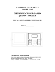
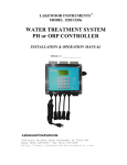
LAKEWOOD INSTRUMENTS
REMOTE
WINDOWS SOFTWARE
USER’S MANUAL
Lakewood Instruments
7838 North Faulkner Road, Milwaukee, WI 53224 USA
Phone (800) 228-0839 • Fax (414) 355-3508
http://www.lakewoodinstruments.com
Lakewood Instruments
We thank you for your selection and purchase of an Lakewood Instruments
software product.
Please take the time to read and understand this User’s Manual, paying special
attention to the information about INSTALLATION, OPERATION and TECHNICAL
SUPPORT.
If, in the future, any customer or technical support is required, we strongly
recommend that you contact us for assistance. Our Customer Service Department
is happy to assist you with all your product and information requests.
Lakewood Instruments Customer Service and Technical Support Departments
can be reached by calling (800) 228-0839 or faxing (414) 355-3508, Monday
through Friday, 7:30 a.m. – 5:00 p.m. Central time.
Mail should be sent to:
Lakewood Instruments
7838 North Faulkner Road
Milwaukee, WI 53224 USA
1
2
LAKEWOOD REMOTE WINDOWS SOFTWARE (LRWS)
Table of Contents
INTRODUCTION
5
INSTALLATION
6
LAKEWOOD REMOTE PROGRAM OPERATION
Controllers
Delete
Modify
New
Connect
The Main Screen
Download
Setup
Modem Settings
Automatic Download
Auto-Answer
Launch
Settings
9
9
10
11
12
13
14
15
17
17
18
23
23
24
LAKEWOOD GRAPH PROGRAM OPERATION
Open Datalog File
Select An Object
Viewing Options
Report
25
26
27
28
29
TECHNICAL SUPPORT
Technical Service/Return Material Procedure
Troubleshooting
31
31
32
3
4
INTRODUCTION
Figure 1: Controller with 1 Relay Node, 2 Conductivity Nodes,
and Drum Level Sensor Connected to Personal Computer
Lakewood Remote Windows Software is a communications program that allows you to
remotely access Lakewood Instruments 2000 Series Controllers for water treatment and
process control via modem or direct connect.
If your controller is equipped with the communications option, Lakewood Remote will
establish an RS-232 connection between it and your computer over a serial port. If your
controller is also equipped with a modem, Lakewood Remote will dial out to the controller
and initiate a modem-to-modem connection. Virtually every one of the programming
options that you can access through the controller's menu/keypad is available over the
serial connection.
5
INSTALLATION
Lakewood Remote runs in Windows 3.1, 95, 98, 2000, NT or XP. It is designed for easy
installation and ease of use. Follow these simple steps to install your copy of Lakewood
Remote:
Insert your Lakewood Remote disk into your floppy disk drive.
Run the application install.exe on the floppy disk.
You will be given the opportunity to determine the directory where the program files will be
installed (see Figure 2 below). LWREMOTE is the factory default that you can select by
clicking on OK. Otherwise, type in a different name using the proper hard drive designator
(i.e., C:\) then click on OK.
Figure 2: Installation Directory
If you have already installed Lakewood Remote on your hard drive, you will see the screen
below (Figure 3) . Click on YES to reinstall the software. Click on NO if you want to retain
the previously installed version.
Figure 3: Overwrite Permission
6
INSTALLATION
The screen below (Figure 4) will appear as your program is being installed. The names of
the files will appear in the first box and the second box will show you the percentage
installation done.
Figure 4: Installation Progress
On most computers, the installation process will take very little time. Upon completion, you
will see the following dialog box, indicating that LRWS Versions 3.1 and higher are Year
2000 compliant.
Figure 5: Installation Complete and Year 2000 Compliant Message
Click on OK and you will see (Figure 6 on next page) that a Windows Program Group was
established with a Lakewood Remote icon and a Lakewood Graph icon.
7
INSTALLATION
Double-click on the Lakewood Remote icon (Figure 6 below) to enter the program.
Figure 6: Windows 95 Program Group Created
If you have difficulties at any time during the installation processs, you may see the
following screen (Figure 7). In most instances, simply closing all other open programs,
and attempting installation again will prove successful.
Figure 7: Unsuccessful Installation Dialog
8
LAKEWOOD REMOTE PROGRAM OPERATION
The screen below is the first screen you will see in Lakewood Remote. It is the Main
Menu. This instruction manual will step you through the menu options beginning with
Modem Preferences so you can select the proper Port and Modem settings that enable
you to use the rest of the Menu options.
Figure 8: LRWS Main Menu Bar
CONTROLLERS
The Controller portion of the Main Menu allows you to identify your controllers. Click on
Controllers to enter this portion of the Menu.
Figure 9: Click on Controllers to Begin
As you can see on the next page (Figure 10), the Controllers screen will be blank—
except for the Lakewood Controller, Milwaukee entries—until you have entered new
controllers. In the future, all the names and phone numbers you have entered will be listed
on this screen for quick and easy selection. (The controller identifier numbers are
automatically generated by the controller the first time it is connected with Lakewood
Remote.) Once you’ve entered this information, you can simply select the controller you
want, then click on Connect and Lakewood Remote will dial up that controller.
9
LAKEWOOD REMOTE PROGRAM OPERATION
Figure 10: Controller Connection Screen
DELETE
Highlight an item and click on Delete if you want to completely remove a controller from
the list. You will be asked whether you want to delete the highlighted item with the
following screen. Click on Yes or No, depending on your choice.
Figure 11: Delete a Controller
10
LAKEWOOD REMOTE PROGRAM OPERATION
MODIFY
Use Modify if you want to make changes to the information entered on a specific
controller (i.e., Name or phone Number).
Figure 12: Modify Controller Information
11
LAKEWOOD REMOTE PROGRAM OPERATION
NEW
To set up a new controller, click on New (see Figure 10) and you will see the following
screen:
Figure 13: Enter a New Controller
Enter a Name for the controller, then press the TAB key. Enter the phone Number for the
controller, then press the TAB key again. A factory-default Password has already been
entered for every new controller input. Unless there is a strict need for security, you
should not enter your own password. If you do, you must also change the password at the
controller as well. Make sure you document that password for future reference as needed.
Select the correct Com Port and Baud Rate for your connection. If you are using a
modem, select the Connection marked Modem; otherwise select RS-232. For most highspeed modems, 19200 baud works fine. If you are using RS-232, you must program the
controller’s baud rate to match the baud rate you select here. The default controller baud
rate for RS-232 is 19200.
12
LAKEWOOD REMOTE PROGRAM OPERATION
CONNECT
Once you have set up a new controller, or a number of them, simply highlight the
controller you want to connect to and click on the Connect button. You will see a
series of screens while the modem dials up the controller. If you have problems
connecting, first make sure you have the proper port and modem settings selected,
then make sure you have the correct number. Make sure your wiring is properly
connected. Finally, refer to the Troubleshooting guide in the program’s Help Menu
for additional assistance. If this does not correct the problem, contact your
Lakewood Instruments Lakewood Instruments Technical Service Representative at
800-228-0839.
Figure 14: Modem Preparation Screen
Figure 15: Connection Screen
13
LAKEWOOD REMOTE PROGRAM OPERATION
THE MAIN SCREEN
After you click on the Connect button, you will see the following screen (Figure
16 below). Take a minute to look at the total screen below, which is an example
from a Model 2412 Controller. The information shown represents the current
readings from your controller. Lakewood Remote frequently updates this
information.
Figure 16: Main Communication Session Screen
The buttons along the bottom of the screen allow you to access the same
controller features that you can access via the controller’s keypad/display. For
example, the Alarms button allows you to view or change the high/low process
alarm values. Additional buttons include:
Options
Program the alarm callout and datalog options. The alarm
callout option allows you to program which alarms cause the controller to call
out to a computer or paging device. The datalog option allows you to select
which values are included in the controller’s datalog.
Time Set the time by clicking on the time-setting button, then type in the
proper time by hours/minutes/seconds.
14
LAKEWOOD REMOTE PROGRAM OPERATION
Date Set the calendar by clicking on the date button, then type in the proper
calendar information by day/date/month/year.
The larger portion of the screen above shows current readings from the
controller. The bottom line, Reading, shows you which elements are being read
and updated.
DOWNLOAD
The controller stores accumulated data selected by the user in its battery-backed
memory. To access this data, click on the Download button. The following
screens will appear:
Figure 17: Download Options Screen
Figure 18: Enter Name of Datalog File
After you enter the name of the datalog file, if you left both forms of downloaded
data selected, you will see a screen titled Download Minutely Data. In a couple
of minutes, the Download Recent Minutely Data will be completed and the
15
LAKEWOOD REMOTE PROGRAM OPERATION
screen will change to reflect Accumulated Hourly Data that is being
downloaded.
Figure 19: Download Progress Screen
HOW THE DATALOG INFORMATION IS CREATED
Conductivity and pH values are datalogged three different ways:
(Avg)
(Hi)
(Lo)
The average reading during that hour.
The high reading during that hour.
The low reading during that hour.
Other datalogged parameters:
(Relay)
(Meter)
Relay on-times are displayed in minutes (from the start of each hour).
Water meter inputs are displayed in gallons or liters.
All alarms are datalogged during the minute they occur and will be included in the
minutely and hourly download. During an alarm condition, all process values
selected to be datalogged will be included in the minutely and hourly download.
16
LAKEWOOD REMOTE PROGRAM OPERATION
Figure 20: Finished Downloading Data
Once the download is completed, you will see the screen above (Figure 20).
You can use Lakewood Graph to view the contents of the datalog file.
You may also have Lakewood Graph export selected data to a comma-delimited
file (extension will be *.prn). You can then import the data into your own
spreadsheet software.
SETUP
MODEM SETTINGS
Click on Setup, then Modem Settings.
Figure 21: Choose Modem Settings
The values shown in the Modem Settings screen on the next page (Figure 22)
are typical settings. For different modem strings, use your modem software
reference manual. For many modems, but not all, these factory-preset defaults
will be the proper settings.
17
LAKEWOOD REMOTE PROGRAM OPERATION
Figure 22: Modem Settings Screen
Click on OK to return to the Main Menu after you make changes or simply review
the settings.
AUTOMATIC DOWNLOAD
Select this option from the Setup Menu to configure Lakewood Remote to call up
one or more controllers at user-specified dates and times in unattended mode.
Figure 23: Select Automatic Download
Lakewood Remote must be running at the date(s) and time that you select in
order for the automatic download to occur. If Lakewood Remote is in AutoAnswer mode, then the Auto-Answer process will be interrupted for the duration
of the automatic download and then resumed at the conclusion of the download.
18
LAKEWOOD REMOTE PROGRAM OPERATION
Figure 24: Automatic Download Schedule Screen
MONTH
Select a month during which you want to perform automatic downloading. The
date calendar to the right will change with the selected month.
CALENDAR
Darken the squares that correspond to the dates on which you want to perform
an automatic download.
START TIME
Select the time (Hours:Minutes, 24-hour clock) when the download is to take
place. Lakewood Remote will attempt to execute the download at this same time
on each one of the selected dates.
19
LAKEWOOD REMOTE PROGRAM OPERATION
CHECK ALL
Push this button to darken every date shown on the calendar for the selected
month.
RESET ALL
Push this button to deselect every date shown on the calendar for the selected
month.
20
LAKEWOOD REMOTE PROGRAM OPERATION
REPORT
Push this button (see Figure 24 on previous page) to bring up a report of
automatic download attempts (successes and failures). The report shows (a) the
date and time that Lakewood Remote attempted the download, (b) the name of
the controller, (c) the event (what happened), which may be one of the following:
Successful Download: The automatic download took place
as scheduled.
Com Port Error: Lakewood Remote could not open the
com port for the indicated controller. You may want to
inspect the com port settings for this controller.
Modem Dial Error: Lakewood Remote could not connect to
the controller via the modem. You may want to test this by
connecting to the controller manually.
User Abort: The user pressed the Cancel button on the
modem dial dialog before Lakewood Remote could
connect to the controller.
Error During Download: An unknown error occurred
during the download. Some of the controller data may
have been saved to the indicated file.
…and (d) the name of the datalog file that contains the downloaded data. The
first five characters of this filename are the same as the File ID that you program
via the Add or Modify buttons; the last three characters are digits with the value
000 through 999. Lakewood Remote increments this 3-digit value each time it
automatically downloads data from a particular controller.
21
LAKEWOOD REMOTE PROGRAM OPERATION
Report entries are logged in order of most recent download attempt first. A
sample report listing might appear as follows:
Figure 25: Report File Named DOWNLOAD.TXT
If you have never downloaded anything, you will get the following screen and a
new DOWNLOAD.TXT file will be created when you click on “Yes”..
Figure 26: Creation of New DOWNLOAD.TXT File
Other examples of what may appear in the automatic download report are seen
below:
Time:
Controller:
Event:
File:
Fri 2 Feb 18:48:55
West Tower
Successful Download.
WTOWR008.LOG
Time:
Fri 2 Feb 18:47:48
Controller: East Tower
Event:
Com Port Error.
If you click on the Add or Modify buttons on the Automatic Download Schedule
screen (see Figure 24) shown earlier, the following screen will appear:
22
LAKEWOOD REMOTE PROGRAM OPERATION
Figure 27: Add or Modify Controller Information
ADD
Click on this button to add a controller to the Automatic Download list.
MODIFY
Click on this button to modify the Automatic Download information for the
selected controller.
DELETE
Click on this button to remove a controller from the Automatic Download list.
The following screen will appear confirming your deletion request.
Figure 28: Confirmation of Delete Function
23
LAKEWOOD REMOTE PROGRAM OPERATION
Auto-Answer
LAUNCH
Lakewood Remote has an Auto-Answer feature that allows you to monitor on your
screen any alarm calls from a controller. All alarms are logged in a text file
(alarmlog.txt is the default name). Simply click on Auto-Answer in the Main Menu
and select Launch…
Figure 29: Launch Auto-Answer Mode
…and the screen Waiting for Alarm Call will appear as shown below.
Figure 30: Waiting for Alarm Call Screen
Click on the View button to display the contents of the Alarm Log. The Alarm Log
file contains a history of callouts from one or more controllers. Leave Lakewood
Remote set at this Waiting for Alarm Call screen, and whenever an alarm call from
a controller occurs, the program logs the time of the call read from both the PC and
the controller, and documents whatever alarms are currently present on the
controller.
Here is an example of a typical entry in the Alarm Log file:
Thu 29 Mar 14:51:15 (PC)
24
LAKEWOOD REMOTE PROGRAM OPERATION
Thu 29 Mar 14:48:19 (West Tower)
NO FLOW
LOW CONDUCTIVITY
The call in the above example arrived on Thursday, the 29th of March at 14:51:15
(according to the PC). The call was made by the controller called “West Tower.”
The time of day read from the controller was Thu 29 Mar 14:48:19. The alarms
present on the controller at the time of the call were NO FLOW and LOW
CONDUCTIVITY.
New alarm calls are logged at the top of the Alarm Log file. Lakewood Remote
does not allow the file to exceed 43,000 bytes. Once the file exceeds that size, the
oldest data at the end of the file starts to disappear.
SETTINGS
Select this option from the Auto-Answer menu to configure your modem for
answering a call from a controller.
Figure 31: Modify Auto-Answer Settings
In order for Lakewood Remote to receive an alarm call from a controller, it must use
the specified com port and baud rate to access your computer's modem. Select the
appropriate COM PORT and BAUD RATE settings for your computer.
Figure 32: Modem Settings for Auto-Answer
There are two ways to enter Lakewood Graph. The first is through the Main Menu of
Lakewood Remote. Click on File, then select Open Logfile.
25
LAKEWOOD GRAPH PROGRAM OPERATION
Figure 33: Open Logfile to Enter Lakewood Graph
The other procedure is to return to the Windows Program Manager, select the Lakewood
Program Group and click on the Lakewood Graph icon to enter Lakewood Graph.
Figure 34: Select Lakewood Graph Icon to Enter Program
26
LAKEWOOD GRAPH PROGRAM OPERATION
OPEN DATALOG FILE
In both cases, the first screen you will see is the Open Datalog File.
Figure 35: Open Datalog File
Under File Name will be a list of previously named datalog files which contain downloaded
information from your controller. In this example, there is a datalog file named
phnx22jl.log located on the C drive in the lwremote directory. In order to operate
Lakewood Graph, you must have a datalog file established, since that is the information
used to create the graphs.
To establish a datalog file, return to Lakewood Remote’s menu and select Controller.
You should Connect to call up a controller, then use the Download function to create a
datalog file.
In Open Datalog File, select the proper drive to retrieve a datalog file by clicking on the
down arrow below Drives, then clicking on A:, B: or C:. Also, you can determine whether
you list all files or just the datalog files in a directory by clicking on the down arrow below
List Files of Type, and you will see the selections Datalog Files (*.log) and Any File
(*.*).
27
LAKEWOOD GRAPH PROGRAM OPERATION
SELECT AN OBJECT
Lakewood Graph will compile information on the object you select. If you select pH (Lo),
for example, then Lakewood Graph will pull the information relevant to pH (Lo) from the
datalog file and graph or export it for you. If no information was downloaded relevant to
the object selected, a named but blank graph will appear.
Figure 36: Select an Object to Graph
While in Lakewood Graph, after having already opened a datalog file, you can select a
new object by clicking on Graph in the Main Menu, then clicking on New in the submenu.
The Select An Object screen will appear again for you to make a new selection.
Subsequent graphs will show the new object you select.
28
LAKEWOOD GRAPH PROGRAM OPERATION
VIEWING OPTIONS
Once you have created a graph and have it on the screen, Lakewood Remote offers some
viewing options (see Figure 37 below). You can select a section of the graph to view
exclusively. Simply click the left mouse button while at one viewpoint, then drag your
cursor to another viewpoint and click the left mouse button again. The box created defines
the graph parameter to be shown in zoom mode. Simply click on the right mouse button to
return to the full-view mode.
As you move the cursor around the graph, note that the Value/Date/Time information
changes at the bottom of the graph to accurately represent the point where the cursor
rests.
Figure 37: Example Graph of COND (Avg)
29
LAKEWOOD GRAPH PROGRAM OPERATION
Report
While in a datalog file, you can select Report from the Main Menu and it will bring up a
Notepad text file that shows the graphed data in the following format:
Figure 38: Example REPORT.TXT of Graphed Data
Note that in this example, the datalog object selected is COND (Avg). This report shows
the measured values for whichever object you select. The report also shows you the drive
and directory where your datalog file is stored. The current date and time are on the line
called Time.
You can export data in comma-delimited format to your own data processing application.
First enter the File Menu and click on Export, or, click on the Export button as shown
below.
Figure 39: Click on Export Button
A screen with a list of parameters, a date field and a time field will appear. Click on the
parameters you want selected, then establish the desired date and time you want included
in the exported data. Click on OK when your selections are completed. Lakewood
30
LAKEWOOD GRAPH PROGRAM OPERATION
Remote will compile a comma-delimited file that can be downloaded and used by many
spreadsheet applications.
Figure 40: Selecting Objects to Export
In the above example, the user has selected COND (Avg), COND (Hi) and COND (Lo) over the
period 16 June 1998, 01:00 to 22 July 1998, 17:00. Clicking OK will create the export file. The
dialog box shown below is displayed upon completion.
Figure 41: Data Export Completed
31
TECHNICAL SUPPORT
If you need technical support for your Lakewood Remote Windows Software:
Technical Service/Return Material Procedure
Lakewood Instruments Technical Support for the LRWS software and related
products can be reached by calling (800) 228-0839 or faxing (414) 355-3508,
Monday through Friday, 7:30 a.m. – 5:00 p.m. Central time.
NOTE: IF YOU CALL FOR TROUBLESHOOTING HELP, PLEASE MAKE SURE THAT
THE MODEL NUMBER, SERIAL NUMBERS AND ANY INFORMATION ABOUT
OPTIONS ARE ALL READILY AVAILABLE FOR REFERENCE.
Mail and returns should be sent to:
Lakewood Instruments
7838 North Faulkner Road
Milwaukee, WI 53224 USA
When any merchandise is returned to the factory, please call and obtain a return goods
authorization order (RGA) number and have the following information available:
•
•
•
•
•
Customer’s name, address, phone and fax numbers (shipping and billing).
A hard copy purchase order number (no exceptions) for cases where repairs or parts
are required that are not under warranty.
A contact person’s name and phone number to call if the equipment is beyond repair
or to discuss any other warranty matter.
Equipment model and serial numbers.
Reason for return, e.g., repair, warranty, incorrect part, etc.
We will then fax to your attention an RGA form that must accompany the returned item.
NOTE: THE RGA NUMBER MUST BE CLEARLY WRITTEN ON THE OUTSIDE OF
THE PACKAGE(S) BEING RETURNED.
ANY ITEMS SENT BACK TO THE FACTORY
WITHOUT AN RGA NUMBER WILL BE REFUSED
AND RETURNED TO SENDER
32
TECHNICAL SUPPORT
Troubleshooting
Here is a small list of common problems and solutions. We'll add to this as future
versions of Lakewood Remote come along.
You can test your Lakewood Remote software on one of our Controllers here at
Lakewood Instruments by dialing out to (414) 355-3628 (if you have a modem, of
course).
Error Opening Serial Port, The Com Port Is Already in Use
You may have another application that runs in Windows that is utilizing the com port,
such as another communications program or fax program. You need to quit the other
application before you can use that serial port with Lakewood Remote.
Error Opening Serial Port, The Com Port is Not Available
You have selected the wrong serial port. You may have a mouse or other device
assigned to this particular serial port. Note that, on many IBMPC-compatible
computers, Windows will not allow you to use Com1 at the same time as Com3, and it
will not allow you to use Com2 at the same time as Com4.
Error Opening Serial Port, Insufficent Memory
Quit one or more applications, and try again.
Error Reading Data from the Controller
If you are never able to get through to the Controller because of read errors, then you
may be using an incorrect baud rate. If you are connecting via RS-232 rather than
modem, then you may be using an incorrect Com port. To change the com port, see
Controllers.
Error Initializing Modem
You may be using the wrong serial port. Or, you may be running at the wrong baud
rate. Try using a very slow baud rate, like 1200. Or, you may be using an incorrect
Modem Initialization String. Refer to your modem documentation (see also Controllers
and Modem Settings).
33
TECHNICAL SUPPORT
Modem Won't Dial Out
Are you getting the "NO DIAL TONE" message? If so, your modem may not be
connected to a phone line, or the phone line may be out of service. You can test this
by connecting a hand receiver to the phone jack and dialing out manually. Or, the
modem initialization may not have worked correctly (see also Modem Settings).
Modem Dials Out, But Doesn't Connect
Are you sure the Controller at the other end of the line is up and running? Try dialing
the Controller's number by voice phone. You should hear a modem squeal once you
dial into the Controller.
Modem Connects, But Lakewood Remote Doesn't Recognize Connection
Try enabling echo on your modem. On most modems, you can do this by adding "E1"
to the Modem Initialization String. Or, you may be attempting to connect an
asynchronous modem to a synchronous modem. If your computer modem can run at
high baud rates (such as 9600 and up), but the Controller's modem only runs at 1200
or 2400, you may need to put your computer's modem into synchronous mode. For
example, on Hayes brand modems, you can do this by adding "&Q0" to the Modem
Initialization String. See also Modem Settings.
Controller Is Always Busy
The Controller may be attempting to call out an alarm at the time you are calling it.
Wait 5 or 10 minutes and try again. Or, someone else may be accessing the
Controller.
34
For more information call toll free in the USA (800) 228-0839
Manufactured in the USA
Lakewood Instruments
7838 North Faulkner Road, Milwaukee, WI 53224 USA
Phone (414) 355-2807 • Fax (414) 355-3508
http://www.lakewoodinstruments.com
© Copyright 1999 Lakewood Instruments
Printed in USA, P/N 1109690 Rev. 3