1
LAKEWOOD INSTRUMENTS™
MODEL 150
BOILER WATER
CONDUCTIVITY CONTROLLER
INSTALLATION & OPERATION MANUAL
SERIAL #: _______________
Lakewood Instruments
7838 North Faulkner Road, Milwaukee, WI 53224 USA
Phone (800) 228-0839 • Fax (414) 355-3508
http://www.lakewoodinstruments.com
Lakewood Instruments™ Model 150 Controller
Quick Installation Sheet
1. Install the controller on a flat, non-vibrating surface. Use the four (4) supplied mounting feet.
Do not mount the controller to a steel object that has a large temperature change (side of
cooling tower, etc). This can cause water to condense inside the enclosure.
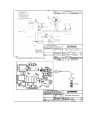
2. Install water meter, chemical pumps, plumbing assemblies and the conductivity sensor (see
drawing on back for suggested installation).
3. Open the front cover of the Model 150 Controller.
4. Wire the flow switch (use jumper wire for no flow switch), conductivity sensor, water meter
and 4-20 mA output, if applicable (see drawing in manual). Ensure wiring connections are
correct or damage may occur.
5. If doing a conduit installation, remove receptacles, and wire pumps and blowdown valve.
Refer to the instruction manual for more details.
6. Use a standard screwdriver to set the power selector switch to either 115 VAC or 230 VAC
operation.
7. Reinstall the front cover keypad making sure the ribbon cable is properly attached.
8. Plug in chemical pumps and blowdown valve to controller (unless hardwired in step #5).
9. Apply power to the model 150 controller, press CLR twice, press 6 System setup, press 2
INITIALIZE, press 2 WHOLE CTRLR, press 1 Yes. After initialization, press the CLR key
several times until you get to the main menu.
10. Press 1 Process, Press ENT. This screen allows manual control of the relay outputs to test
the chemical pumps and blowdown valve. Press the number for the relay you want to
operate; 1 for bleed, 2 for relay 2, and 3 for relay 3. The box will flash to show that that relay
is in manual control. To restore automatic control press that number again. Press CLR to
return to the Process screen.
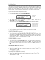
11. To calibrate conductivity take a sample with a handheld conductivity meter, press the PRO
button, type in conductivity value, press ENT (skip if not using conductivity sensor). For more
details refer to appropriate section of this manual
12. Program the model 150 relays for blowdown, chemical feed schemes, water meter input, and
4-20 mA output. See instruction manual for more details.
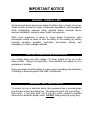
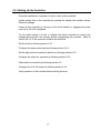
IMPORTANT NOTICE
WARNING: CHEMICAL FEED
All electromechanical devices are subject to failure from a variety of causes.
These include mechanical stress, component degradation, electromagnetic
fields, mishandling, improper setup, physical abuse, chemical abuse,
improper installation, improper power feeds, and exposure.
While every precaution is taken to insure proper functioning, extra
precautions should be taken to limit the ability of over-feeding by limiting
chemical quantities available, secondary shut-downs, alarms, and
redundancy or other available methods.
CAUTION: POWER SOURCE AND WIRING
Low voltage wiring and high voltage (110 plus) should not be run in the
same conduit. Always run separately. Even shielded low voltage is not a
guarantee of isolation.
Every precaution should be taken to insure proper grounding and elimination
of shorting or Electromagnetic field (EMF) interference.
WARNING: ELECTRICAL SHOCK
To reduce the risk of electrical shock, this equipment has a grounding-type
plug that has a third (grounding) pin. This plug will only fit into a grounding type outlet. If the plug does not fit into the outlet, contact a qualified
electrician to install the proper outlet. DO NOT change the plug in any way.
-2-
Lakewood Instruments
We thank you for your selection and purchase of a Lakewood
Instruments product.
With proper care and maintenance, this device should give you many
years of trouble-free service. Please take the time to read and
understand this Installation and Operation Manual, paying special
attention to the sections on OPERATION and MAINTENANCE.
If, in the future, any parts or repairs are required, we strongly
recommend that only original replacement parts be used. Our
Customer Service Department is happy to assist you with your parts or
service requests.
Lakewood Instruments Customer Service and Technical Support
Departments can be reached by calling (800) 228-0839 or faxing
(414) 355-3508, Monday through Friday, 7:30 a.m. - 4:30 p.m. CST.
Mail should be sent to:
Lakewood Instruments
7838 North Faulkner Road
Milwaukee, WI 53224 USA
-3-
-4-
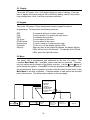
MODEL 150
Table of Contents
1.0 Introduction........................................................................................................7
2.0 Features, Benefits and Specifications................................................................8
2.1 Features..................................................................................................8
2.2 Benefits...................................................................................................9
2.3 Specifications..........................................................................................9
2.4 Ordering Information ..............................................................................10
3.0 Unpacking, Mounting and Installation................................................................ 11
3.1 Unpacking...............................................................................................11
3.2 Mounting the Enclosure..................................................................... .....11
3.3 Plumbing Installation...............................................................................12
3.3.1 Orifice Sizing chart........................................................................13
3.4 Electrical Installation............................................................................... 14
3.4.1 Incoming power 115/230 VAC....................................................... 14
3.4.2 Relay Outputs................................................................................ 15
3.4.3 Flow Switch Wiring...................................................................... ..15
3.4.4 Sensor Wiring................................................................................ 16
3.4.5 Water Meter................................................................................... 16
3.4.6 4-20 mA Output Wiring.................................................................. 16
4.0 Starting Up the Controller................................ ......................................... ........17
5.0 Functional Overview.................................................................................... ......18
5.1 Front Panel.............................................................................................. 18
5.2 Display....................................................................................................19
5.3 Keypad.................................................................................................... 19
5.4 Menu....................................................................................................... 19
5.4.1 Menu Flow Chart ..........................................................................20
6.0 Operation of the Controller................................................................................ 21
6.1 Process Screen....................................................................................... 21
6.2 Manual Operation of the Relays.............................................................. 22
6.3 Calibration of Conductivity....................................................................... 22
6.3.1 Calibration in Continuous Sample Boiler Control ......................22
6.3.2 Calibration in Sample/Cycle Boiler Control ...............................23
6.3.3 Calibration in Sample Hold Boiler Control.................................23
6.4 Main Menu............................................................................................... 24
6.4.1 Process Screen ........................................................................24
6.4.2 Configuring the Relays .............................................................25
6.4.2.1 Configuring the Blowdown Relay ................................25
6.4.2.1.1 Setpoint Values........................................... 26
6.4.2.1.1.1 Deadband ................................26
6.4.2.1.1.2 Blow Alarm Time .....................27
6.4.2.1.2 When to Blow.............................................. 27
-5-
6.4.2.1.3 Boiler Methods............................................27
6.4.2.1.3.1 Continuous Sample .................28
6.4.2.1.3.2 Sample/Cycle ..........................28
6.4.2.1.3.3 Sample Hold ............................29
6.4.2.1.4 Ball Valve Delay..........................................31
6.4.2.2 Configuring Relays 2 and 3......................................... 31
6.4.2.2.1 Disabled...................................................... 31
6.4.2.2.2 By Setpoint .................................................32
6.4.2.2.2.1 Setpoint.........................................32
6.4.2.2.2.2 Deadband .....................................33
6.4.2.2.2.3 Timeout .........................................33
6.4.2.2.2.4 When to Feed ...............................34
6.4.2.2.3 By Water Meter...........................................34
6.4.2.2.4 By % of Blowdown Time .............................34
6.4.2.2.5 By Percent of Time .....................................35
6.4.2.2.6 As an Alarm Relay ......................................36
6.4.3 Alarms....................................................................................... 36
6.4.4 Water Meter ..............................................................................37
6.4.5 Setup of the 4-20 mA Out .........................................................38
6.4.5.1 Set the 4-20 mA Range............................................... 38
6.4.5.2 Manual Control............................................................ 38
6.4.5.3 Calibrate the 4-20 mA Output...................................... 38
6.4.6 System Setup Menu................................................................ 39
6.4.6.1 Process Parameters....................................................39
6.4.6.1.1 Anti-Flashing...............................................39
6.4.6.1.2 Enable/Disable the Conductivity Input ........40
6.4.6.2 Initialize .......................................................................40
6.4.6.3 Firmware Version ........................................................40
6.4.7 Setting the Clock..................................................................... 41
7.0 Maintenance....................................................................................................... 42
7.1 Sensor Maintenance................................................................................ 42
7.2 Replacing the Fuses................................................................................ 43
8.0 Troubleshooting.................................................................................................. 44
8.1 Error Messages....................................................................................... 44
9.0 Factory Service................................................................................................... 46
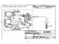
10.0 Drawings
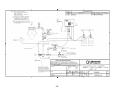
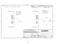
10.1 Wiring Boiler Sensor............................................................ 1269089_1A
10.2 Suggested Installation Layout ............................................. 1269089_2A
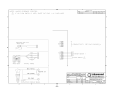
10.3 Wiring Water Meter.............................................................. 1269089_3A
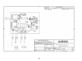
10.4 Wiring Power Connections .................................................. 1269089_5A
10.5 Wiring 4-20 mA Output ........................................................ 1269089_6A
-6-
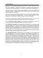
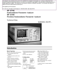
1.0 Introduction
The Model 150 is a microprocessor based, menu driven, controller designed for use in
boiler water applications. The Model 150 provides for conductivity tracking and control,
flow monitoring and chemical injection. The Model 150 is NTL/CSA, and CE approved.
The Model 150 uses the latest in microprocessor capability, giving the user a high level of
application flexibility. A digital display screen, multiple inputs, and an intuitive menu
characterize this new technology.
The Model 150 is user-friendly with a graphical screen, numeric keypad, LEDs for power,
alarm, flow, relay status, and display lighting. It accepts multiple inputs and is easily
configured. It’s a combination of reliability, accuracy, security and simplicity.
The model 150 is designed to control boiler water blowdown by use of any of the three
boiler control methods; Continuous Sample, Sample/Cycle, or Sample Hold.
In the Continuous Sample method, the controller will continuously monitor the
conductivity reading and control the blowdown relay based on setpoint.
In the Sample/Cycle method, the blowdown relay will energize for a user selected time
called the Sample Time. At the end of the Sample Time the controller will compare the
conductivity reading to the setpoint and if the conductivity is higher than the setpoint the
Blowdown relay will stay energized until the conductivity reading is less than the setpoint.
Once the setpoint is satisfied the blowdown relay will turn off for a user selected time
called the Cycle Time. At the end of the Cycle Time the Blowdown relay will once again
go into the Sample Time and repeat the above sequence.
In the Sample Hold mode, the blowdown relay will energize for a user selected time
called the Sample Time. At the end of the Sample Time the blowdown relay will turn off
and the controller will go into a 30 second Hold Time. The Hold Time allows time for the
sample to stop flashing before actually reading the conductivity value. At the end of the
Hold Time, the controller will go into a Reading Time of 15 seconds. At the end of the
Reading Time, the controller will compare the conductivity reading to the setpoint. If the
conductivity is higher than the setpoint, the controller will go into a user selected Blow to
Resample Time and re-energize the blowdown relay repeat the above sequence. Once
the setpoint is satisfied the controller will keep the blowdown relay turned off for a user
selected time called the Cycle Time. At the end of the Cycle Time the Blowdown relay
will once again go into the Sample Time and repeat the above sequence.
-7-
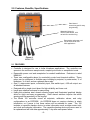
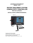
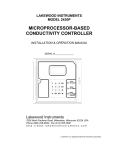
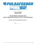
2.0 Features, Benefits, Specifications
Steel domed
numeric keypad for easy
programming
Watertight fittings for
sensor, water meters, 4-20
mA and flow switch wiring
Receptacles and power cord
can be removed for 240
VAC applications
Figure 1:
Model 150
2.1 FEATURES
• Controller is designed for use in boiler blowdown applications. The controller can
operate in the continuous sample mode, sample/cycle mode, or sample/hold mode.
• Removable power cord and receptacles for conduit installations. Enclosure is rated
NEMA 4X
• Three user configurable relays for conductivity control and chemical addition. These
relays can be configured in multiple ways including by setpoint, by water meter, % of
blowdown, % of time, and as a general alarm relay.
• One (1) water meter inputs, conductivity input, flow switch input, 4-20 mA output, are
all standard features.
• Designed with a single circuit board for high reliability and lower cost.
• Large open shallow enclosure for easy wiring.
• Heavy-duty stainless steel domed numeric keypad and illuminated graphical display
allow for quick and easy programming. Steel domed switches improve the tactile
sensing and life expectancy of the keypad.
• The Model 150 controller stores all setpoints, calibration values, and relay
configurations in an EEPROM. An EEPROM does not require a battery to retain
information, so if power is lost these values will be retained for years. The 150
includes a capacitive backup device to retain information such as water meter total,
and clock and calendar information. The capacitive backup device will never need to
be replaced and will hold data approximately 1 day after each power failure.
-8-
2.2 BENEFITS
• Easy to program, the Model 150 Controller uses an intuitive menu and a numeric
keypad for programming.
• No add-on options. Flow switch input, 4-20mA output, and three boiler conductivity
control methods are standard.
• Multiple feed configuration methods available in a single controller.
2.3 Specifications
Conductivity range
100-10,000 µS
Water meter input (1)
Contact head, paddle wheel or Autotrol
turbine
Conductivity sensor
Two-electrode
Timer
Relay run time exceeded.
Conductivity Resolution
10 µS
Output Signal
One 4 – 20 mA, isolated or non-isolated
optionally powered output for conductivity.
Accuracy & repeatability
± 1.0% of scale
Output relays
3 selectable use
Deadband/Setpoint
User programmable
Relay ratings
3A each, 10A total
Auto/Manual outputs
Menu selectable
Power
120/240 VAC 50/60 Hz 6W
Keypad
16 tactile steel-dome push buttons
Ambient temp
32° - 150°F (0 - 60°C)
Display
16 X 2 Character
Storage temp
-4° - 150°F (-20 - 65°C)
Enclosure
NEMA 4x
-9-
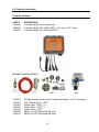
2.4 Ordering Information
Controller Options
PART #
1269089
1269092
1269093
DESCRIPTION
Controller Model 150 controller only
Controller Model 150, w/SR2, MBV-1, 1/2" union, 1/16" orifice
Controller Model 150, w/SR2 and PLKT
BOILER SYSTEM OPTIONS
SR2
1168374
1233981
1166355
1166354
1167244
1268608
1268614
PLKT
MBV1
SR2 Boiler water sensor with 20 ft cable and elbow. ¾ NPT connection.
PLKT Plumbing Kit, ½ NPT
Orifice Plate, ½ NPT, 1/16.
Orifice Plate, ½ NPT, 1/8.
Orifice Union, ½ NPT.
MBV1 ½ in NPT Motorized ball valve.
MBV2 ¾ in NPT Motorized ball valve.
10
3.0 Unpacking, Mounting and Installation
3.1 Unpacking
Inspect the shipping carton for obvious external damage. Note on the carrier's billof-lading the extent of the damage, if any, and notify the carrier. Save the
shipping carton until your Model 150 controller is started up.
If shipping damage has occurred, call the Lakewood Instruments Customer
Service Department at (800) 228-0839 and return the controller to the factory
in the original carton.
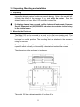
3.2 Mounting the Enclosure
The Model 150 can be mounted to a panel or to a flat non-vibrating wall. The
Model 150 includes four removable mounting feet that can be attached in the
horizontal or vertical position. The mounting feet are attached to the enclosure
using four screws.
To change the position of the mounting feet: remove the screws from the feet and
reposition either vertically or horizontally as desired and reattach the screws.
The dimensions of the enclosure in inches are:
The model 150 has a shipping weight of less than 6 lbs.
11
3.3 Plumbing Installation
There are three methods of automatic control of the conductivity in a boiler; sample/cycle,
continuous sample, and sample/hold. To decide if you should use continuous sample, or
sample/cycle or sample/hold control, determine your blowdown rate requirement. If your
boiler requires greater than 1000 pounds per hour of blowdown to maintain conductivity
then the continuous sample method should be used. If your blowdown requirement is less
than 1000 pounds per hour, the sample/cycle or sample/hold methods are appropriate.
The model 1575e can be used for either sample/cycle control, sample/hold control, or
continuous sample control of the conductivity in the boiler. The installation drawing in the
back of this manual shows how to plumb the boiler sample line so that it can be used as
sample/cycle, sample/hold, or continuous sample.
To prevent steam flashing and damage to the sensor and controller refer to the installation
drawings in the back of this manual and the notes below.
•
Use piping from the boiler skimmer line as the sample and blowdown line.
NOTE: DO NOT USE THE BOTTOM BLOWDOWN OF THE BOILER AS THE
SAMPLE OR AUTOMATIC BLOWDOWN LINE.
•
The maximum allowed wire distance between the controller and the sensor is 20 ft.
•
If using conduit between the sensor and controller, allow a place for water to escape if
the sensor leaks. This will help prevent water damage to the controller.
•
Use orifice plates or globe valves to prevent steam flash. The orifice plates or the
globe valve should be mounted within 5 feet of the sensor. Orifice plates (or globe
valve) and the sensor must be installed horizontally (as shown in the drawing).
•
The sensor should be located at least two feet below the water level in the boiler.
•
Ensure that there are no restrictions between the skimmer line and the orifice plates (or
globe valve) and all valves upstream of the boiler sensor are fully open.
•
Be sure to provide isolation valves in the sample line to allow for maintenance of the
sensor.
•
Refer to section 3.3.1 for the orifice sizing chart
NOTE: DO NOT RUN THE SENSOR WIRING IN THE SAME CONDUIT AS
THE MOTORIZED VALVE WIRING.
12
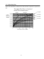
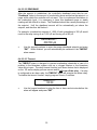
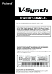
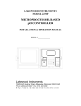
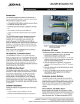
3.3.1 Orifice Sizing Chart
Refer to the chart below to determine the orifice size that is required for a specific flow
rate.
Throughput Flow Rate as a function of
Orifice Size & Steam Pressure
150 PSIG
100 PSIG
15 PSIG
0.500
0.450
250 PSIG
Orifice
Diameter 0.400
, Inches 0.350
500 PSIG
900 PSIG
0.300
0.250
0.200
0.150
0.100
0.050
0.000
0
5
10
15
20
Flow Rate, lb./hr (X 1000)
13
25
30
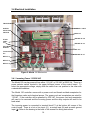
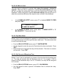
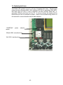
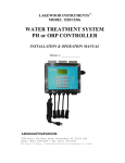
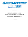
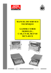
3.4 Electrical Installation
TRANSFORMER
POWER
SELECTOR
SWITCH
RIBBON CABLE
FUSES
100mA
10A
TERMINAL P-8
DISPLAY
TERMINAL P-2
INCOMMING
POWER
RELAYS
Terminal blocks
For:
TERMINAL P-7
RELAY #1
RELAY #2
RELAY #3
Figure 2: Model 150 Electronics
3.4.1 Incoming Power 115/230 VAC
The Model 150 can be powered from either 115 VAC or 230 VAC at 50/60 Hz. There is a
power selector switch located in the upper left-hand corner of the control board. To
select the appropriate voltage, simply slide the switch from one position to the other with
a standard screwdriver.
The Model 150 controller comes with a power cord and female molded receptacles for
the blowdown valve and chemical pumps. The power cord and receptacles are rated for
115VAC. If the controller will be powered by 230 VAC, the power cord and receptacles
will need to be removed and the incoming power and the relay outputs will need to be
hard-wired.
The incoming power is connected to terminal block P1 at the bottom left corner of the
control board. There is a hot or line input (L1), a neutral input (N) and an earth ground
input ( ). Refer to the drawing in the back of this manual for wiring instructions.
14
3.4.2 Relay Outputs
The relay outputs are of the same voltage as the power input. Ensure that the devices
that are to be connected to the relay outputs are of the same voltage rating or damage
will occur.
The relay outputs are wired to the female molded receptacles. The molded receptacle on
the far left is relay #1 and the molded receptacle on the far right is relay #3. If 115 VAC is
used simply plug your devices into the molded receptacles. If 230 VAC is used, remove
the receptacles and hard-wire your devices to the relay outputs.
Relay #1 has both a normally open and normally closed contact. This is designed for use
with any device that requires either or both types of contacts for operation, such as a
motorized blowdown valve. The normally open (NO) contact energizes when the relay
turns on and the normally closed (NC) contact is energized when the relay turns off. The
other three relays only have a normally open contact. Each relay output has a neutral (N)
connection and an earth ground connection ( ) connection.
To operate the terminal blocks to remove or add wiring, insert a small screwdriver into the
slot above each wiring connection and pry upward while removing or inserting the wire.
Refer to the drawing in the back of this manual for wiring instructions.
3.4.3 Flow Switch Wiring
The model 150 has a flow switch input. The purpose of the flow switch input is to disable
the relay #2 and #3 outputs on a loss of flow in the system. Relay #1 is not controlled by
the flow switch input. The flow switch input requires a dryl contact. Any digital contact
rated for 24 VDC and 500 mA may be used, such as a relay driven by the recirculating
pump. The flow switch input is wired to terminal block P7 terminals 1 and 2.
If a flow switch is not used then a jumper must be installed across the flow switch
connections in order for relays #2 and #3 to function. Refer to the drawings in the back of
this manual for wiring instructions.
15
3.4.4 Sensor Wiring
The model 150 uses the Lakewood Instruments two-electrode conductivity boiler sensor.
The maximum recommended wiring distance for sensor is 20 feet.
The conductivity sensor is wired directly to the P8 terminal block on the upper right corner
of the control board. The black and white wires are wired to terminal # 1 (I+). The red
and green wires are wired to terminal # 2 (I-). Terminals # 3 and # 4 are not used.
NOTE: DO NOT RUN THE SENSOR WIRING IN THE SAME CONDUIT AS THE
MOTORIZED VALVE WIRING.
3.4.5 Water Meter
The Model 150 will accept one water meter input.
manufacturer’s manual for plumbing information.
Refer to the water meter
The 150 series controller will work directly with the following types of meters: dry
contacting head meters, Seametrics open collector output meters, Signet 2535 and 2540
paddle wheel meters, and the Autotrol 1 inch and 2 inch meters. Contact Lakewood
Instruments for other types of water meters. The water meters are wired to terminal block
P7 on the right-hand side of the control board. Refer to the drawing in the back of this
manual for wiring instructions.
3.4.6 4-20 mA Output Wiring
The model 150 has one 4-20 mA output for conductivity. This output can be isolated or
non-isolated, externally powered or internally powered. If the 4-20 mA output is internally
powered then it is non-isolated. If the 4-20 mA output is externally powered then it is
isolated.
The 4-20 mA output is wired to terminal block P2 on the right-hand side of the control
board. Refer to the drawing in the back of this manual for wiring instructions.
16
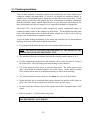
4.0 Starting Up the Controller
Once the Installation is complete it is time to start up the controller.
Initiate sample flow to the controller by opening the sample line isolation valves.
Check for leakage.
Power up the controller by turning on the circuit breaker or plugging the power
cord into a 120 VAC receptacle.
For the initial startup it is best to initialize the whole controller to remove any
settings that may be in the memory before programming the controller. Refer to
section 6.4.6.2 of this manual to initialize the controller.
Set the clock by following section 6.4.7.
Configure the water meter input by following section 6.4.4.
Set the high and low conductivity alarms by following section 6.4.3.
Configure the relays for operation by following section 6.4.2.
Calibrate the conductivity by following section 6.3.
Configure the 4-20 mA output by following section 6.4.5.
Verify operation of the controller before leaving the area.
17
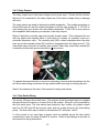
5.0 Functional Overview
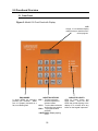
5.1 Front Panel
Figure 3: Model 150 Front Panel with Display
LCD
A large, 16 x 2 character display
makes it easy to read the menudriven program
ENCLOSURE
A sturdy NEMA 4X enclosure
protects your controller. Make
sure it is properly mounted on a
flat, non-vibrating wall.
16-BUTTON KEYPAD
ENT = For Menu selection
and/or acceptance of
selected values.
CLR = To exit a Menu selection
and/or skip input options.
PRO = To program a Menu
selection.
LIGHT BULB= Display lighting
on/off.
18
INDICATOR LIGHTS
LEDs for Power, Alarm, and
Relay status. There are also
LEDs that provide lighting to the
display for 5 minutes when any
button on the keypad is pressed.
5.2 Display
The model 150 uses a 16 x 2 LCD digital display for ease of viewing. It has two
lines to display information such as the conductivity reading, alarms, relay status,
relay configuration, clock, total flow, and menu selections.
5.3 Keypad
The model 150 uses a 16-key steel-domed numeric keypad for ease of
programming. The keys have the following functions:
ENT
CLR
PRO
UP arrow
DOWN arrow
Number keys
Light bulb
Any Key
To accept a setting or to enter a screen.
To exit a screen or to access the main menu.
To calibrate the controller.
To move about in the menu.
To move about in the menu.
To input a value or to select a menu item.
To turn on or off the display lighting LEDs.
When any key on the keypad is pressed, the display lighting
LEDs will turn on for five minutes. To manually turn off these
LEDs, press the light bulb button.
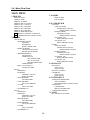
5.4 Menu
The model 150 is programmed and calibrated by the use of a menu. The
complete Main Menu has 7 available options that can be accessed. However,
only one option can be viewed on the display at a time. Use the Ï and Ð keys to
scroll through the options. Press ENT to enter the displayed programming option.
As an introduction, here is a graphic overview of the first level of each option in the
Main Menu to see how it operates. Complete details of each option are provided
later in this manual. The entire menu is shown on the next page.
1
2
3
4
5
6
7
1
1500 µS
RLY: B 2 3
2
WHICH RELAY?
1 BLOW
2 RLY2
3 RLY3
MAIN MENU
=============
PROCESS
RELAYS
ALARMS
WATER METER
4-20 MA OUT
SYSTEM SETUP
CLOCK
3
4
5
HIGH ALM=2000µS
LOW ALM=1000 µS
MTR1: GALS/LTRS?
1*GALLONS
2 LITERS
4-20 MA OUTPUT
1 SET RANGE
2 MANUAL CTRL
3 CALIBRATE
19
6
7
SYSTEM SETUP
THU 18 FEB ‘10
1 INITIALIZE
2 FIRMWARE VER
05:42:40
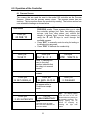
5.4.1 Menu Flow Chart
MAIN MENU
3 ALARMS
1 PROCESS
HIGH ALARM
LOW ALARM
DISPLAY DATE
DISPLAY TIME
DISPLAY ALARMS
DISPLAY RELAY STATUS
DISPLAY RLY 1 STATUS
DISPLAY RLY1 SETTING
DISPLAY RLY2 SETTING
DISPLAY RLY3 SETTING
DISPLAY WTR MTR TOTAL
ENT-MANUAL CONTROL OF RELAYS
PRO-CALIBRATION OF CONDUCTIVITY
4 WATER METER
GALLONS
CONTACT HEAD
ENTER GALS/CONTACT
RESET METER COUNTS
PADDLE WHEEL
ENTER K-FACTOR
RESET METER COUNTS
AUTOTROL 1 IN.
RESET METER COUNTS
AUTOTROL 2 IN.
RESET METER COUNTS
LITERS
CONTACT HEAD
ENTER GALS/CONTACT
RESET METER COUNTS
PADDLE WHEEL
ENTER K-FACTOR
RESET METER COUNTS
AUTOTROL 1 IN.
RESET METER COUNTS
AUTOTROL 2 IN.
RESET METER COUNTS
2 RELAYS
1 BLOW RELAY
1 SETPOINT VALUES
SETPOINT
DEADBAND
BLOW ALARM TIME
2 WHEN TO BLOW
ABOVE THE SETPOINT
BELOW THE SETPOINT
3 BOILER METHODS
CONTINUOUS
SAMPLE/CYCLE
SET SAMPLE TIME
SET CYCLE TIME
SET RESAMPLE TIME
SAMPLE/HOLD
4 BALL VALVE DELAY
SET DELAY TIME
2 RLY 2
1 DISABLED
2 SETPOINT
SETPOINT VALUES
WHEN TO FEED
3 WATER METER
SET FEED TIME
4 % BLOWDOWN
SET % BLOWDOWN
5 % TIME
SET % ON-TIME
6 ALARM RELAY
3 RLY 3
1 DISABLED
2 SETPOINT
SETPOINT VALUES
WHEN TO FEED
3 WATER METER
SET FEED TIME
4 % BLOWDOWN
SET % BLOWDOWN
5 % TIME
SET % ON-TIME
6 ALARM RELAY
5 4-20 MA OUT
SET RANGE
4 MA VALUE
20 MA VALUE
MANUAL CONTROL
CALIBRATE
4 MA VALUE
20 MA VALUE
6 SYSTEM SETUP
1 PROCESS PARAMETERS
ANTI-FLASHING
ENABLE/DISABLE CONDUCTIVITY
2 INITIALIZE
CALIBRATION
WHOLE CONTROLLER
3 FIRMWARE VERSION
7 CLOCK
SET THE DATE AND TIME
20
6.0 Operation of the Controller
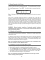
6.1 Process Screen
The screens that are used the most in the model 150 controller are the Process
Screens. Below are the process screen views. The process screen has two
sections. The top section shows the conductivity reading. The bottom section has
user selectable readings as shown below.
1 - DATE SCREEN
1000 µs
25 FEB ‘10
2 TIME SCREEN
1000 µS
15:58:11
•
There are many different screens available in the
PROCESS screen. These screens allow you to view
the controller settings (incl. Date, time setting, relay
set-ups, total flow, relay status, etc.) without the
danger of altering them. Access these screens by
using the Ï and Ð keys to scroll through the
available screens.
• Press “ENT” to manually control a relay for testing or
troubleshooting purposes.
• Press “PRO” to calibrate the conductivity.
3
ALL RELAY SCREEN
1000 µS
RLY: B 2 3
4
WATER METER SCREEN
1000µS
MTR: 100273 G
Note: A flashing box
next to the relay
number indicates that
the relay is in manual
control.
5 BLOWDOWN RELAY SCREEN
6 BLOWDOWN SAMPLE/CYCLE
SCREEN
1000 µS
1000 µS
B: SET=99999 µS
B: SMPL 00:00:59
6 RELAY #2 SCREEN
1000 µS
2: DISABLED
Note: This screen does
not appear while in
Continuous sample
mode.
7 RELAY #3 SCREEN
1000 µS
3: BY WATER MTR
8 ALARM SCREEN
100 µS
LOW CONDUCTIVITY
NOTE:
THE DISPLAYED ALARMS
WILL ROTATE THROUGH ALL
ACTIVE ALARMS.
21
Note: The display lighting
LEDs will turn on for five
minutes when any button on
the keypad is pressed. The
display lighting can be
turned off manually by
pressing the light bulb
button.
6.2 Manual Operation of the Relays
All three of the relays can be operated manually. To manually operate the relays:
Go to the Process screen. Press “ENT”. You will be taken to a screen that looks
like:
MANUAL-RLY 5 MIN
RLY: B 2 3
Note: A flashing box next to the relay number indicates that the relay is in manual
control.
Press “1-3“ to manually change the state of a particular relay. If the relay is
already on, pressing that number will turn it off. A five-minute countdown timer will
start and the box next to the relay number will start to flash. After five minutes has
expired the relay will return to automatic control. The relay will remain in manual
control even if this screen is exited. A relay that is in manual control will stay in
manual control until the five minutes expires or until that relay number is pressed
again. The five-minute timer helps to prevent damage to the system if a relay is left
in manual.
WARNING:
Manual control overrides all automatic control functions
including the flow switch lockout. Use care when operating relays manually
with no flow in the system.
6.3 Calibration of Conductivity
The conductivity requires periodic calibration. Calibration is usually required after
cleaning the sensor.
A calibration should always be performed with the sensor in the piping assembly
with good flow past the sensor. It is necessary to have an accurate reading of the
system water to properly calibrate the controller. A hand-held conductivity meter
that tests the sample works well for this purpose.
Note: The controller will allow up to one minute to enter a calibration value
while the controller is in the calibration mode.
6.3.1 Calibration in Continuous Sample Boiler Control
•
•
•
•
Ensure that the controller is operating with good flow past the sensor.
Take a sample of the water and measure with a hand-held conductivity tester.
From the PROCESS screen, press “PRO” to enter the calibration screen. Use
the keypad to input the conductivity reading from the hand-held. Press “ENT”.
Take another hand-held sample to verify calibration.
Note: The controller will remain in the calibration mode for only 1 minute
before resuming normal operation.
22
6.3.2 Calibration in Sample/Cycle Boiler Control
•
•
•
Ensure that the controller is operating with good flow past the sensor.
Take a sample of the water and measure with a hand-held conductivity tester.
From the PROCESS screen, press “PRO” to enter the calibration mode. The
controller will turn on the Blowdown relay for 30 seconds and display the
following screen:
PLEASE WAIT
OBTAINING SAMPLE
•
At the end of the 30 second sample time, the Blowdown relay will turn off and
the controller will display the following screen:
CALIBRATION:
03200 µS :59
•
•
Use the keypad to input the conductivity reading from the hand-held. Press
“ENT”.
Take another hand-held sample to verify calibration.
Note: The controller will remain in the calibration mode for only 1 minute
before resuming normal operation.
6.3.3 Calibration in Sample Hold Boiler Control
•
•
•
Ensure that the controller is operating with good flow past the sensor.
Take a sample of the water and measure with a hand-held conductivity tester.
From the PROCESS screen, press “PRO” to enter the calibration mode and
will start obtaining a sample. The controller will display the following message:
PLEASE WAIT
OBTAINING SAMPLE
•
After the sample is obtained, the controller will display:
CALIBRATION:
03200 µS :59
•
•
•
Use the keypad to input the conductivity reading from the hand-held before the
timer reaches 0:00. Press “ENT”.
The controller will respond with “CALIBRATION COMPLETE”.
Take another hand-held sample to verify calibration.
Note: It takes approx. 1 minute and 30 seconds to obtain a sample then the
controller will remain in the calibration mode for only 1 minute before
resuming normal operation.
23
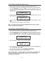
6.4 Main Menu
The MAIN MENU of the model 150 consists of 7 menu selections:
1.
2.
3.
4.
5.
6.
7.
Process – Displays process conditions.
Relays – Relay configuration screens.
Alarms – Set the high and low conductivity alarms.
Water meter – Configure water meter type and reset total flow.
4-20 MA Out – Set up and calibrate the 4-20 ma output.
System Setup – Initialize the controller and view firmware version.
Clock – Set the date and time.
Only one menu selection will appear on the screen at a time. Main Menu always
appears in the top half of the screen. The bottom half of the display shows the
selectable item in the menu. The screen will look like this:
MAIN MENU
1 PROCESS
1.
2.
3.
4.
5.
6.
PROCESS
RELAYS
ALARMS
WATER METER
4-20 MA OUT
SYSTEM SETUP
7. CLOCK
The MAIN MENU can be accessed from the PROCESS screen by pressing
“CLR”.
To move about in the menu screens use the Ï and Ð keys to display the desired
selection and press “ENT” or press the number key for the desired selection to
access that selection.
Use the “ENT” key to accept a setting or to enter a screen. Use the “CLR” key to
reject a setting or to exit a screen. From anywhere in the menu, pressing “CLR”
will take you one step closer to the MAIN MENU.
Each of the MAIN MENU options is discussed in detail later in this manual.
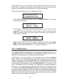
6.4.1 The Process Screen
The process screen is where the conductivity value is displayed. The process
screen is discussed further in section 6.1.
24
6.4.2 Configuring the Relays
To access the relay configuration screen from the MAIN MENU, press “2” or
highlight RELAYS and press “ENT”. The following screen will appear.
WHICH RELAY?
1 BLOW
1 Blow
2 RLY2
3 RLY3
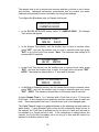
6.4.2.1 Configuring the Blowdown Relay
The blowdown relay can be configured to operate in three different modes:
Continuous Sample, Sample/Cycle, or Sample Hold. Each of these modes are
explained further in the Boiler Methods section of this manual. NOTE: The
blowdown relay is not affected by the flow switch input.
In Continuous Sample mode, the Blowdown relay works strictly by setpoint
control.
In Sample/Cycle mode, the Blowdown relay will energize for a user selected time
called the Sample Time. At the end of the Sample Time the controller will
compare the conductivity reading to the setpoint and if the conductivity is higher
than the setpoint the Blowdown relay will stay energized until the conductivity
reading is less than the setpoint. Once the setpoint is satisfied the Blowdown
relay will turn off for a user selected time called the Cycle Time. At the end of the
Cycle Time the Blowdown relay will once again go into the Sample Time and
repeat the above.
In the Sample Hold mode, the Blowdown relay will energize for a user selected
time called the Sample Time. At the end of the Sample Time the Blowdown relay
will turn off and the controller will go into a 30 second Hold Time. The Hold Time
allows time for the sample to stop flashing before actually reading the conductivity
value. At the end of the Hold Time, the controller will go into a Reading Time of
15 seconds. At the end of the Reading Time, the controller will compare the
conductivity reading to the setpoint. If the conductivity is higher than the setpoint,
the controller will go into a user selected Blow to Resample Time and re-energize
the Blowdown relay repeat the above sequence. Once the setpoint is satisfied the
controller will keep the Blowdown relay turned off for a user selected time called
the Cycle Time. At the end of the Cycle Time the Blowdown relay will once again
go into the Sample Time and repeat the above.
When the blowdown relay is selected for programming the following screen will
appear.
BLOWDOWN SETUP:
1 SETPT VALUES
25
1 SETPNT VALUES
2 WHEN TO BLOW
3 BOILER METHOD
4 BALL VALVE DL
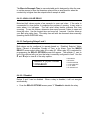
6.4.2.1.1 Setpoint Values
In the SETPT VALUES screen you will set the SETPOINT, the DEADBAND and
the BLOW ALARM TIME alarm.
The SETPOINT is the conductivity value that you are trying to maintain. Check
with your water treatment engineer to determine the conductivity setpoint for your
system needs.
Follow these instructions to establish the controller's setpoint:
•
Press “1” or highlight SETPT VALUES and press ”ENT”.
SETPOINT=
4500 µS
•
Use the keypad numbers to enter the proper conductivity setpoint and press
”ENT”. When finished, you will automatically be moved down to the
deadband.
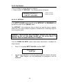
6.4.2.1.1.1 DEADBAND
After the setpoint is established, the controller's deadband must also be set.
"Deadband" refers to the amount of conductivity above and below the setpoint—a
range within which the controller will not react. Due to continuous fluctuations in
the conductivity level, it is necessary to have this deadband range or stable
readings will be difficult to obtain. The Deadband should be a small percentage of
the setpoint. Half the deadband amount will be automatically put above the
setpoint, and the other half below it.
For example, a conductivity setpoint of 1,000 µS with a deadband of 100 µS would
result in the BLOWDOWN relay opening at 1,050 µS and closing at 950 µS.
DEADBAND=
000100 µS
•
Use the keypad numbers to enter the proper deadband setpoint and press
”ENT”. When finished, you will automatically be switched to the BLOW
ALARM TIME alarm screen.
26
6.4.2.1.1.2 BLOW ALARM TIME
The BLOW ALARM TIME alarm is designed to notify the operator of a problem in
the blowdown system such as, a clogged strainer or the blowdown valve did not
open. The blowdown timeout function is strictly a visual alarm feature displayed on
the model 150 controller−it will not close the blowdown valve. If a relay is
configured as an alarm relay, the BLOW ALARM TIME alarm will energize the
alarm relay. To disable this function, simply program 0 hours, 0 minutes.
BLOW ALARM TIME=
00:00
•
Use the keypad numbers to enter the time in hours and minutes before this
alarm will appear and press ”ENT”.
Note: The BLOW ALARM TIME alarm only applies to the Continuous Sample
control mode.
6.4.2.1.2 When to Blowdown
Most applications for boilers will blowdown above the setpoint. If desired, it is
possible to configure the relay with a reverse setpoint. That is, blowdown occurs
below the setpoint. If using this method be sure that the high conductivity alarm is
set as high as possible.
•
In the BLOWDOWN SETPT screen, press “2” or highlight WHEN TO
BLOW and press ”ENT”.
WHEN TO BLOWDOWN
1*ABOVE SETPT
•
In the WHEN TO BLOWDOWN screen, select either ”1” ABOVE SETPT or
”2” BELOW SETPT. Then press any key. An asterisk(*) will appear next to
the current selection.
6.4.2.1.3 BOILER METHODS
The Blowdown relay can be configured for Continuous Sample, Sample/Cycle, or
for Sample Hold mode. The Boiler Methods screen is selectable under the
Blowdown setup screen:
BLOWDOWN SETPT:
3 BOILER METHOD
•
In the BLOWDOWN Setup screen, select "3" BOILER METHOD.
27
6.4.2.1.3.1 CONTINUOUS SAMPLE
In Continuous Sample boiler applications, blowdown water is continuously
flowing past the conductivity sensor and the controller is controlling the Blowdown
relay based on a setpoint.
This mode is usually used for large boilers or boilers with very little condensate
return. It is recommended that you use this mode if your blowdown rate
requirement is greater than 1000 lbm/hr.
To configure the Blowdown relay for Continuous Sample mode:
BOILER METHODS:
1 CONTINUOUS
•
In the BOILER METHODS screen, select "1" CONTINUOUS. The controller
will respond with "CONTINUOUS SAMPLE press any key". Press any key to
return to the BOILER METHODS SCREEN.
6.4.2.1.3.2 SAMPLE/CYCLE
In Sample/Cycle boiler applications, the controller will sample the water on a
timed basis and then control based on a conductivity setpoint. This mode is
usually used for smaller boilers or boilers with a large amount of condensate
return. It is recommended that you use this mode if your blowdown rate
requirement is less than 1000 lbm/hr.
The Blowdown relay will energize for a user selected time called the Sample Time
(the amount of time the blowdown valve will be open). At the end of the Sample
Time the controller will compare the conductivity reading to the setpoint and if the
conductivity is higher than the setpoint the Blowdown relay will stay energized until
the conductivity reading is less than the setpoint. Once the setpoint is satisfied the
Blowdown relay will turn off for a user selected time called the Cycle Time (the
amount of time the blowdown valve will be closed). At the end of the Cycle Time
the Blowdown relay will once again energize and go into the Sample Time and
repeat the above sequence.
A typical Sample Time is 1 to 2 minutes with a Cycle time of up to 17 hours and
59 minutes. A short sample time is desired to prevent excessive loss of water and
heat. Once the sample time is set, it should never have to be changed again.
The Cycle Time will need to be adjusted based on the steaming rate and make-up
water quality. If using Sample/Cycle control and the conductivity does not rise to
the setpoint, the Cycle time is probably set for too short of a time and will need to
be adjusted to a longer period of time. If the conductivity is always above the
setpoint, the Cycle time is probably set at too long of a time and will need to be
adjusted to a shorter period of time.
28
The Sample time is set in minutes and seconds and the Cycle time is set in hours
and minutes. Lakewood Instruments recommends that you consult your water
treatment professional for more information on using these settings.
To configure the Blowdown relay for Sample/Cycle mode:
BOILER METHODS:
2 SAMPLE/CYCLE
•
In the BOILER METHODS screen, select "2" SAMPLE/CYCLE. The Sample
Time screen will appear.
SAMPLE TIME=
MM:00 SS:00
•
In the Sample Time screen, use the number keys to input a minutes value,
press "ENT", and use the number keys to enter a seconds value and press
"ENT" to go to the Cycle Time screen. Note: The maximum time setting is 59
minutes and 59 seconds.
CYCLE TIME=
HH:00 MM:00
•
In the Cycle Time screen, use the number keys to input an hours value, press
"ENT", and use the number keys to enter a minutes value and press "ENT".
NOTE: The maximum allowed time is 17 hour and 59 minutes.
6.4.2.1.3.3 SAMPLE HOLD
In the Sample Hold boiler applications, the controller will sample the water on a
timed basis and then control based on a conductivity setpoint just like in the
Sample/Cycle method above but with an added Hold feature.
The Blowdown relay will energize for a user selected time called the Sample
Time. At the end of the Sample Time the Blowdown relay will turn off and the
controller will go into a 30 second Hold Time. The Hold Time allows time for the
sample to stop flashing before actually reading the conductivity value. At the end
of the Hold Time, the controller will go into a Reading Time of 15 seconds. At the
end of the Reading Time, the controller will compare the conductivity reading to
the setpoint. If the conductivity is higher than the setpoint, the controller will go
into a user selected Blow to Resample Time and re-energize the Blowdown relay
to repeat the above sequence. Once the setpoint is satisfied the controller will
keep the Blowdown relay turned off for a user selected time called the Cycle
Time. At the end of the Cycle Time the Blowdown relay will once again go into the
Sample Time and repeat the above sequence.
29
The sample time is set in minutes and seconds and the cycle time is set in hours
and minutes. Lakewood Instruments recommends that you consult your water
treatment professional for more information on using these settings.
To configure the Blowdown relay for Sample Hold mode:
BOILER METHODS:
3 SAMPLE HOLD
•
In the BOILER METHODS screen, select "3" SAMPLE HOLD. The Sample
Time screen will appear.
SAMPLE TIME=
MM:00 SS:00
•
In the Sample Time screen, use the number keys to input a minutes value,
press "ENT", and use the number keys to enter a seconds value and press
"ENT" to go to the Cycle Time screen. Note: The maximum time setting is 59
minutes and 59 seconds.
CYCLE TIME=
HH:00 MM:00
•
In the Cycle Time screen, use the number keys to input an hours value, press
"ENT", and use the number keys to enter a minutes value and press "ENT".
NOTE: The maximum allowed time is 17 hour and 59 minutes.
BLOW TO RESAMPL=
MM:00 SS:00
•
In the Blow to Resample screen, use the number keys to input a minutes value,
press "ENT", and use the number keys to enter a seconds value and press
"ENT". NOTE: The maximum allowed time is 59 minutes and 59 seconds.
A typical Sample Time is 1 to 2 minutes with a Cycle time of up to 17 hours and
59 minutes. A short sample time is desired to prevent excessive loss of water and
heat. Once the sample time is set, it should never have to be changed again.
The Cycle Time will need to be adjusted based on the steaming rate and make-up
water quality. If using Sample/Cycle control and the conductivity does not rise to
the setpoint, the Cycle time is probably set for too short of a time and will need to
be adjusted to a longer period of time. If the conductivity is always above the
setpoint, the Cycle time is probably set at too long of a time and will need to be
adjusted to a shorter period of time.
30
The Blow to Resample Time is user selectable and is designed to allow the user
to set the amount of time the blowdown relay will be re-energized for when the
conductivity is higher than the setpoint after a sample is taken.
6.4.2.1.4 BALL VALVE DELAY
Motorized ball valves require a few seconds to open and close. If the valve is
commanded to close before it completes the process of opening, it may enter a
state where it is half-open. The ball valve delay feature prevents this from
occurring. To use this feature, determine how many seconds it takes to open and
close the valve. Use the longest time and round up 1 second. Use this value as
your Ball valve delay time. This delay time will also be observed when manually
operating the BLOWDOWN relay.
6.4.2.2 Configuring Relays 2 and 3
Both relays can be configured to operate based on: Disabled, Setpoint, Water
Meter, Percent of blowdown, Percent of Time, or by Alarm. From the WHICH
RELAY? screen select either relay #2 or relay #3. When relay 2(3) is selected for
programming the RELAY OPTIONS screen will appear. The asterisk (*) next to
one of the options tells you how that relay is currently configured to feed. Use the
Ï and Ð keys to view all of the relay options.
RELAY 2 (3) OPTIONS
1 DISABLED
1 DISABLED
2 SETPOINT
3 WATER METER
4 % BLOWDOWN
5 % OF TIME
6 ALARM RELAY
6.4.2.2.1 Disabled
Relays 2 and 3 can be disabled. When a relay is disabled, it will not energize
automatically.
•
From the RELAY OPTIONS screen press “1” Disabled to disable the relay.
31
6.4.2.2.2 By Setpoint
To set up a relay to operate based on a setpoint:
• Press or select “2” SETPOINT. The following screen will appear.
BASED ON SETPT
1 SETPT VALUES
1 SETPT VALUES
2 WHEN TO FEED
6.4.2.2.2.1 SETPOINT
In the SETPT VALUES screen you will set the SETPOINT, the DEADBAND and
the amount of time for the TIMEOUT alarm.
The SETPOINT is the conductivity value at which you want the relay to operate.
Check with your water treatment engineer to determine the conductivity setpoint
for your system needs.
WARNING: THE SETPOINT AND DEADBAND VALUES FOR THIS RELAY
SHOULD BE SET AT THE SAME VALUES AS THE BLOW RELAY TO
PREVENT OVER OR UNDER FEEDING OF CHEMICAL.
From the BASED ON SETPT screen follow these instructions to establish the
relay’s setpoint:
•
Press “1” or highlight SETPT VALUES and press ”ENT”.
SETPOINT=
4500 µS
•
Use the keypad numbers to enter the proper conductivity setpoint and press
”ENT”. When finished, you will automatically be prompted to set the
deadband.
32
6.4.2.2.2.2 DEADBAND
After the setpoint is established, the controller's deadband must also be set.
"Deadband" refers to the amount of conductivity above and below the setpoint—a
range within which the controller will not react. Due to continuous fluctuations in
the conductivity level, it is necessary to have this deadband range or stable
readings will be difficult to obtain. The Deadband should be a small percentage of
the setpoint. Half the deadband amount will be automatically put above the
setpoint, and the other half below it.
For example, a conductivity setpoint of 1,000 µS with a deadband of 100 µS would
result in the relay turning on at 1,050 µS and turning off at 950 µS.
DEADBAND=
000100 µS
•
Use the keypad numbers to enter the proper deadband setpoint and press
”ENT”. When finished, you will automatically be switched to the TIMEOUT
alarm screen.
6.4.2.2.2.3 Timeout
The TIMEOUT alarm is designed to prevent overfeeding chemicals in case of a
problem in the blowdown system such as, a clogged strainer or the blowdown
valve did not open. The relay timeout function is an alarm feature that is displayed
on the 150 series display process screen and it will turn off the relay. If a relay
is configured as an alarm relay, the TIMEOUT alarm will energize the alarm relay.
To disable the timeout function, simply program 0 hours, 0 minutes.
TIMEOUT=
00:00
•
Use the keypad numbers to enter the time in hours and minutes before this
alarm will appear and press ”ENT”.
33
6.4.2.2.2.4 When to feed
The relay can be configured to operate either above the setpoint or below the
setpoint. When the relay is configured to operate above the setpoint, the relay
will turn on when the conductivity rises above the setpoint plus one-half of the
deadband. When configured to operate below the setpoint, the relay will turn on
when the conductivity falls below the setpoint minus one-half of the deadband.
•
In the BASED ON SETPT screen, press “2” or highlight WHEN TO FEED
and press ”ENT”.
WHEN TO FEED
1*ABOVE SETPT
•
In the WHEN TO FEED screen, select either ”1” ABOVE SETPT or ”2”
BELOW SETPT. Then press any key.
6.4.2.2.3 By Water Meter
Relays 2 and 3 can be configured to operate for a specified amount of time based
on a specified amount of flow through the water meter input. The water meter total
is used to activate the relay.
•
•
•
From the RELAY OPTIONS screen press ”3” WATER METER.
Use the keypad to enter the amount of flow before the relay is activated. Press
”ENT”.
Enter the amount of time that the relay will be activated. This time is in minutes
and seconds. Press ”ENT”.
6.4.2.2.4 By Percent of Blowdown Time
Relays 2, and 3 can be activated by a percent of the time that the blowdown was
on. The relay will activate after the blowdown shuts off. For example, if 50% is
entered and the blowdown relay is on for 10 minutes, the relay will be energized
for 5 minutes.
•
•
From the RELAY OPTIONS screen, press ”4” % BLOWDOWN.
Use the keypad to enter a percent of blowdown time to activate this relay.
Press ”ENT”.
34
6.4.2.2.5 By Percent of Time
The Percent of Time feature allows you to feed chemical strictly based by a
percent of time. This relay control scheme works in patterns of 20-second time
blocks. A relay is on for some multiple of 20 seconds and off for some multiple of
20 seconds. Below is a chart showing some of the operation times for Percent of
Time.
Percent On Time Off Time 1% 5% 10% 25% 33% 50% 66% 75% 90% 95% 99% 20 Sec 20 Sec 20 Sec 20 Sec 20 Sec 20 Sec 40 Sec 60 Sec 180 Sec (3 m) 380 Sec (6m20S) 1980 Sec (33m) 1980 Sec (33m) 380 Sec (6m20S) 180 Sec (3 m) 60 Sec 40 Sec 20 Sec 20 Sec 20 Sec 20 Sec 20 Sec 20 Sec Note: In the case of “33%”, once every 66 minutes, the “off” time would extend an
extra 20 seconds to make up for the accumulation of the odd % value vs. a 24
hour clock, since the percent of time is based on a 24HR clock in 20 second
increments. The same could be said for the “66%” timer, except it will remain “ON”
for the additional 20 seconds every 66 minutes.
To determine the total amount of chemical fed over a 24 hour period, multiply the
percent of time by the number of hours a day that your controller is operating, then
multiply by your chemical pump flow rate per hour.
For example:
We select 10% of the time, our controller operates 24 hours a day and our
chemical pump flow rate is 1 gallon per hour.
10% x 24 hours x 1gallon = 2.4 Gallons
Day
Hour
Day
•
•
From the RELAY OPTIONS screen press ”5” PERCENT OF TIME.
Use the keypad to enter the percentage of time desired. Press ”ENT”.
35
6.4.2.2.6 As an Alarm Relay
Relays #2 and 3 can be configured as alarm relays. Any alarm will cause the relay
to activate. These alarms include: HIGH Conductivity, LOW Conductivity, BLOW
ALARM TIMEOUT, RELAY #2 TIMEOUT, RELAY #3 TIMEOUT, and the NO
FLOW alarm.
•
From the RELAY OPTIONS screen press ”6” ALARM RELAY. The controller
will respond with the following screen.
ACTVE ON ANY ALM
press any key
NOTE: A relay that is configured as an alarm relay will be activated any time
any alarm including the “NO FLOW” alarm is present.
6.4.3 Alarms
The Model 150 is equipped with both high and low conductivity alarms. This menu
option allows you to program the specific values for these alarms. When a
conductivity alarm is received, it will appear as a flashing message in the alarm
screen and any configured alarm relays will be activated. Consult your water
treatment specialist when determining the proper High and Low Alarm values for
your system.
To get to the alarm settings:
•
From the MAIN MENU press ”3” ALARMS.
HIGH ALM= 5000µS
LOW ALM= 100µS
•
•
Use the keypad to enter a value for the high alarm. Press ”ENT”.
Use the keypad to enter a value for the low alarm and press ”ENT”.
36
6.4.4 Water Meter
The model 150 controller will work directly with the following types of meters: dry
contacting head meters, Seametrics open collector output meters, paddle wheel
meters such as the Signet 2535 and 2540, and the Autotrol 1 inch and 2 inch
turbine meters. Contact Lakewood Instruments for other types of water meters.
To get to the water meter configuration screen:
•
From the main menu, press ”4” WATER METERS.
MTR1: GALS/LTRS?
1*GALLONS
•
•
The water meter can be configured for gallons or liters. Press ”1” for
GALLONS or press ”2” for LITERS.
This will take you to the WATER METER TYPES screen as shown below.
WATER MTR TYPES
1 CONTACT HEAD
•
1 GALLONS
2 LITERS
1 CONTACT HEAD
2 PADDLE WHEEL
3 AUTOTROL 1 IN
4 AUTOTROL 2 IN
Use the keypad to select the type of water meter that you are using.
If CONTACTING HEAD is selected:
•
You will be taken to the GALLONS OR LITERS PER CONTACT screen. Use
the keypad to enter the number of gallons or liters per contact for your specific
meter then press ”ENT”. You will then be asked if you want to reset the meter
count to zero. Press ”1” for YES or press ”2” for NO.
If PADDLE WHEEL is selected:
•
You will be taken to the K-FACTOR screen. Use the keypad to enter the Kfactor for your particular water meter then press ”ENT”. You will then be asked
if you want to reset the meter count to zero. Press ”1” for YES or press ”2” for
NO.
If AUTOTROL TURB 1 IN. is selected:
•
You will be asked if you want to reset the meter count to zero. Press ”1” for
YES or press ”2” for NO.
If the AUTOTROL TURB 2 IN. is selected:
•
You will be asked if you want to reset the meter count to zero. Press ”1” for
YES or press ”2” for NO.
37
6.4.5 Set Up of the 4-20 mA Output
The model 150 has one 4-20 mA output that is configured for conductivity.
To set up the 4-20 mA output:
•
From the Main Menu, press ”5” 4-20 mA OUT.
There are three things that can be done from the 4-20 mA Out Setup screen; set
the 4-20 mA range, take manual control of the 4-20 mA output and calibrate the 420 mA output. Below is the 4-20 mA Setup screen.
4-20 MA OUTPUT
1 SET RANGE
1 SET RANGE
2 MANUAL CTRL
3 CALIBRATE
6.4.5.1 Set the 4-20 mA Range
The 4-20 mA output range must be set for the output to be useful.
•
•
•
From the 4-20 mA OUTPUT screen, press ”1” Set the 4-20 mA RANGE.
Use the keypad to enter a conductivity value for the 4-mA point. Press ”ENT”.
Use the keypad to enter a conductivity value for the 20-mA point. Press ”ENT”.
6.4.5.2 Manual Control
Manual control is used to temporarily change the 4-20 mA output.
•
•
From the 4-20 mA Setup screen, press ”2” MANUAL CONTROL.
Use the up and down arrow keys to raise or lower the 4-20 mA output. To exit
this screen and restore automatic control of the 4-20 mA output press ”CLR”.
6.4.5.3 Calibrate the 4-20 mA Output
The 4-20 mA needs to be calibrated to the actual output to be accurate. A
milliamp meter is necessary to calibrate the 4-20 mA output. Connect the milliamp
meter in-line with one leg of the 4-20 mA output. Refer to the drawing in the back
of this manual for wiring instructions.
•
•
•
From the 4-20 mA OUTPUT screen, press ”3” CALIBRATE.
Use the keypad to enter the milliamp reading from the milliamp meter for the 4mA point. Press ”ENT”.
Use the keypad to enter the milliamp reading from the milliamp meter for the
20-mA point. Press ”ENT”.
38
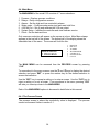
6.4.6 System Setup Menu
The system setup menu is used to initialize the controller or calibration, and check
the firmware version.
To reach the SYSTEM SETUP MENU:
•
From the MAIN MENU press “6” SYSTEM SETUP. The following screen will
appear.
SYSTEM SETUP
1 PROCESS PARMS
1 PROCESS PARMS
2 INITIALIZE
3 FIRMWARE VER
6.4.6.1 Process Parameters
The Process Parameters screens allow the user to enable the Anti-Flashing
feature and to enable or disable the conductivity input.
To reach the PROCESS PARAMETERS MENU:
•
From the SYSTEM SETUP MENU press “1” PROCESS PARMS. The
following screen will appear.
PROCESS PARAMS
1 ANTI-FLASHING
1 ANTI-FLASHING
2 ENABL/DISABL
6.4.6.1.1 Anti-Flashing
The anti-flashing menu selection inserts a damping circuit value into the
conductivity circuit to slow down the rate of change of the conductivity when steam
flashing is occurring.
To enable the anti-flashing feature:
•
•
•
•
From the Main Menu press ”6” SYSTEM SETUP.
Press ”1” PROCESS PARAMS.
Press ”1” ANTI-FLASHING.
Press ”1” YES to enable anti-flashing, press ”2” NO to disable anti-flashing.
39
6.4.6.1.2 Enable/Disable the Conductivity Input
The Model 150 can be used with or without the conductivity input. If conductivity is not
being used, disable the conductivity input.
•
•
•
•
From the Main Menu press ”6” SYSTEM SETUP.
Press ”1” PROCESS PARAMETERS.
Press ”2” ENABL/DISABL.
Press ”1” YES to enable the conductivity input or press ”2” NO to disable the
conductivity input.
NOTE: When the conductivity is disabled, the Process screen will display the status of the
three relays in the top section of the display in place of the conductivity reading.
6.4.6.2 Initialize
Initialization restores the factory default settings to the controller. The whole
controller can be initialized or just the calibration. It is suggested that you initialize
the whole controller before you program the controller for the first time. This will
clear any random settings that may be in the controller. To do so, follow these
instructions:
•
•
•
From the Main Menu, press ”6” SYSTEM SETUP.
Press ”2” INITIALIZE.
Press ”2” WHOLE CTRLR. You will then be asked “ARE YOU SURE?”.
Press ”1” for YES or press ”2” for NO.
To initialize just the calibration:
•
Press ”1” CALIBRATION instead of ”2” WHOLE CONTROLLER in the
procedure above. The same message will appear.
6.4.6.3 Firmware Version
Sometimes it is necessary to verify the firmware version of the controller for
troubleshooting purposes. To get to the firmware version:
•
•
•
From the Main Menu, press ”6” SYSTEM SETUP.
Press ”3” FIRMWARE VER.
The firmware version will be displayed along with a checksum value. The
checksum value is used to verify that the program has not been corrupted. To
exit this screen, press any key.
40
6.4.7 Setting the Clock
The clock uses the 24 hour or military time. 06:00:00 is 6 a.m. 18:00:00 is 6 p.m.
To set the clock:
•
From the Main Menu press ”7” CLOCK. The following screen will appear:
WED 24 FEB ‘10
15:02:41
•
•
•
•
•
•
•
•
•
Press ”PRO” to change the clock settings. The day will start flashing.
Use the up and down arrow keys to change the day of the week. Press ”ENT”.
Use the number keys to change the date. Press ”ENT”.
Use the arrow keys to change the month. Press ”ENT”.
Use the number keys to change the year. Press ”ENT”.
Use the number keys to change the hour. Press ”ENT”.
Use the number keys to change the minutes. Press ”ENT”.
Use the number keys to change the seconds. Press ”ENT”.
Press ”CLR” to exit this screen.
You must press “ENT” all the way through this menu for the settings to take affect.
41
7.0 Maintenance
Periodic maintenance is required to ensure trouble free operation of the model 150
controller. The following sections cover the required maintenance.
7.1 Sensor Maintenance
Routine maintenance is necessary in order to maximize the efficiency and
accuracy of your sensor. Clean the electrode end of the conductivity sensor at
least once per month. Cleaning of the conductivity sensor may need to be
performed more frequently if it is in a high fouling environment.
•
•
•
•
•
•
•
•
•
•
•
Remove power from the controller and shut off the sample flow.
Remove the sensor from its plumbing.
Use a wire brush to lightly brush the sensor tips. Do not use cloth to clean the
sensor tips. Cloth has oils that will foul the sensor.
If there is oil on the sensor tips, use isopropyl alcohol to clean the tips.
If there is scale on the sensor tips use a 10% Muriatic or HCL acid to clean the
sensor.
Wash the sensor off with tap water.
Install the sensor in its plumbing.
Restore sample flow and check for leaks.
Restore power to the controller.
Perform a calibration of the conductivity.
Verify operation before leaving area.
42
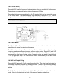
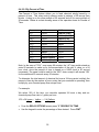
7.2 Replacing the Fuses
The Model 150 contains a two 5 x 20 mm, European-style fuses. Replacement
fuses must be a Schurter 0034.1526, Littlefuse 217.010, or equivalent 10A, 250V,
fast blow type for Fuse F1 and a Littlefuse 218.100, Schurter 0034.3107, or
equivalent 100mA, slow blow for Fuse F2. If a fuse is blown, the display will be
blank when the unit is connected to power. Refer to the troubleshooting section of
this manual for more information about blank displays.
115/230VAC
switch
power
selector
100mA, 250V, slow blow fuse
10A, 250V, fast blow fuse
43
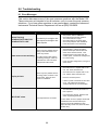
8.0 Troubleshooting
8.1 Error Messages
This section discusses some of the more common questions with the Model 150.
These notes are not intended to be all-inclusive—only to cover the most common
situations. If you have other questions or are need support, contact the Lakewood
Instruments Technical Service Department toll free at (800) 228-0839.
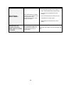
PROBLEM
{Alarm Flashing}
“CONDUCTIVITY HIGH” OR
“CONDUCTIVITY LOW”
WHAT THIS MEANS
Conductivity is too high or low
with respect to the high or low
alarm setpoint.
There may be a problem with the
wiring or the reed switch in the
meter may be bad.
Water meter not accumulating.
Display is blank.
“NO FLOW” alarm.
For water meters other than the
contacting head type, check the
manufacturer’s user manual for
that particular water meter.
There may be a problem with the
incoming power, the fuses or the
circuit board. Open the front
panel to troubleshoot.
CORRECTIVE ACTION
1.
2.
3.
4.
5.
6.
See problem “RELAY TIMEOUT”.
Check the chemical pump operation.
The chemical drum is empty.
Check the High or Low Alarm Value.
Check relay setpoints and deadbands.
Insure the system is not overflowing.
1.
Approximately 5 volts DC should be
present at the input terminal when the
water meter contact is closed. That
should change to zero VDC when the
contact opens. Check these voltages and
for correct wiring.
2.
Is the controller configured for your type of
water meter?
1.
Check the fuse F1. Replace with 5 x 20
mm, 10A, 250V, fast blow fuse.
2.
Check the fuse F2. Replace with 5 x 20
mm, 100mA, 250V, slow blow fuse.
3.
Does the unit have power?
4.
If there is power to terminals AC and ACC
on P1, call Lakewood Instruments
Technical Service for more information.
1.
The flow switch float may be stuck or no
flow is present.
2.
Flow switch may be bad. Replace reed
switch in plumbing assembly.
Flow input switch is not closed.
If no flow switch is used, a jumper wire should
be installed across the flow switch input.
Removing the jumper disables the relay
outputs for relays 2 and 3 but, does not affect
the Blow relay.
44
PROBLEM
{Alarm Flashing}
“RELAY TIMEOUT”.
Motorized ball valve
functions, but will not
remain “open” or “closed”
as expected.
WHAT THIS MEANS
This indicates that the controller
has been trying to operate a relay
for longer than the userprogrammed time and is unable
to reach the setpoint.
The motorized ball valve is not
indicating to the 150 that it has
actually reached the open or
closed position.
45
CORRECTIVE ACTION
1.
Check for proper operation of the pump or
valve. Use the manual relay control to help.
2.
Check the relay configuration and verify
settings.
3.
Check chemical levels in the drums or totes.
4.
Verify operation of water meters.
5.
Momentarily shut off system flow to reset
alarms.
Adjust the limit switch for the motorized ball
valve.
9.0 Factory Service
Technical Support for Lakewood Instruments can be reached by calling (800)
228-0839 or faxing (414) 355-3508, Monday through Friday, 7:30 a.m. - 4:30
p.m. CST.
NOTE: IF YOU CALL FOR TROUBLESHOOTING HELP, PLEASE HAVE THE
MODEL NUMBER, SERIAL NUMBER, AND ANY OPTIONS PERTAINING TO
YOUR UNIT AVAILABLE FOR REFERENCE.
Mail and returns should be sent to:
Lakewood Instruments
7838 North Faulkner Road
Milwaukee, WI 53224 USA
When any merchandise is to be returned to the factory, please call and obtain a
Return Goods Authorization (RGA) number and have the following information
available:
•
•
•
•
•
Customer’s name, address, telephone and fax numbers (shipping and billing).
A hard copy purchase order number for cases where repairs or parts are
required that are not under warranty.
A contact person’s name and telephone number to call if the equipment is
beyond repair or to discuss any other warranty matter.
Equipment model and serial numbers.
Reason for return, e.g., repair, warranty, incorrect part, etc.
We will then fax to your attention an RGA form that must accompany the returned
item.
NOTE: THE RGA NUMBER MUST BE CLEARLY WRITTEN ON THE OUTSIDE
OF THE PACKAGE(S) BEING RETURNED.
ANY ITEMS SENT BACK TO THE FACTORY
WITHOUT AN RGA NUMBER WILL BE REFUSED
AND RETURNED TO SENDER
46
Service Guide
When calling Lakewood Instruments, please have your controller’s complete
model number and serial number available, together with the firmware version so
that the Technician can better assist you.
Refer to the Ordering Information section of this manual for part numbered
replacement parts.
Write your controller’s complete model number, serial number, and firmware
version here so that you will have them available if you wish to contact a
Lakewood Instruments technician.
Model Number:
Serial Number:
Firmware Version:
- 47 -
10.0 Drawings
- 48 -
- 49 -
- 50 -
- 51 -
- 52 -
- 53 -
- 54 -
- 55 -
For more information call toll free in the USA (800) 228-0839
Manufactured in the USA
LAKEWOOD INSTRUMENTS
7838 North Faulkner Road, Milwaukee, WI 53224 USA
Phone (800) 228-0839 • Fax (414) 355-3508
http://www.lakewoodinstruments.com
©Copyright 2010 Lakewood Instruments LLC.
Printed in USA, Rev. 1