1
LAKEWOOD INSTRUMENTS
MODEL 2450e
MICROPROCESSOR-BASED
REVERSE OSMOSIS MONITOR
INSTALLATION & OPERATION MANUAL
SERIAL #: _______________
Lakewood Instruments
7838 North Faulkner Road, Milwaukee, Wisconsin 53224 USA
Phone (800) 228-0839 • Fax (414) 355-3508
http://www.lakewoodinstruments.com
2
IMPORTANT NOTICE
CAUTION: CHEMICAL FEED
All electromechanical devices are subject to failure from a variety of causes. These
include mechanical stress, component degradation, electromagnetic fields,
mishandling, improper setup, physical abuse, chemical abuse, improper installation,
improper power feeds and exposure.
While every precaution is taken to insure proper functioning, extra precautions
should be taken to limit the ability of over-feeding by limiting chemical quantities
available, secondary shut-downs, alarms and redundancy or other available
methods.
CAUTION: POWER SOURCE AND WIRING
Low voltage wiring and high voltage (110 plus) should not be run in the same
conduit. Always run separately. Even shielded low voltage is not a guarantee of
isolation.
Every precaution should be taken to insure proper grounding and
elimination of shorting or Electromagnetic field (EMF) interference.
3
4
Lakewood Instruments
We thank you for your selection and purchase of a Lakewood
Instruments product.
With proper care and maintenance, this device should give you
many years of trouble-free service. Please take the time to read
and understand this Installation and Operation Manual, paying
special attention to the sections on OPERATION and
MAINTENANCE.
If, in the future, any parts or repairs are required, we strongly
recommend that only original replacement parts be used. Our
Customer Service Department is happy to assist you with your
parts or service requests.
Lakewood Instruments Customer Service and Technical
Support Departments can be reached by calling (800) 2280839 or faxing (414) 355-3508, Monday through Friday, 7:30
a.m. - 5:00 p.m. CST.
Mail should be sent to:
Lakewood Instruments
7838 North Faulkner Road
Milwaukee, WI 53224 USA
5
6
MODEL 2450e
Table of Contents
1.0 INTRODUCTION .............................................................................................. 10
2.0 Benefits, Features, Specifications................................................................. 11
2.1 Ordering Information ........................................................................... 12
2.2 Front Panel Description....................................................................... 13
3.0 Unpacking, Mounting and Installation .......................................................... 14
3.1 Unpacking............................................................................................. 14
3.2 Mounting the Enclosure ...................................................................... 14
3.3 Sensor Installation ............................................................................... 15
3.3.1 Conductivity Sensor Plumbing ............................................. 15
3.3.2 Conductivity Sensor Wiring................................................... 15
3.3.3 pH/ORP Sensor Plumbing...................................................... 16
3.3.4 pH/ORP Sensor Wiring........................................................... 16
3.4 Electrical Installation ........................................................................... 17
3.4.1 Incoming Power 115/230 VAC ............................................... 17
3.4.2 Relay Wiring............................................................................ 17
3.4.3 CIP Switch Wiring..................................................................... 18
3.4.4 Flow Meter Wiring .................................................................... 18
3.4.5 4-20 mA Output Wiring ............................................................ 18
4.0Functional Overview........................................................................................ 19
4.1 Display .................................................................................................. 19
4.2 Keypad .................................................................................................. 19
4.3 Menu...................................................................................................... 19
4.4 Security Levels..................................................................................... 20
5.0 Starting Up the Monitor .................................................................................. 21
5.1 Initial Power Up .................................................................................... 21
5.2 Initialization .......................................................................................... 21
5.3 Conductivity Preamp Setup ................................................................ 22
5.4 Cell Constant ........................................................................................ 22
5.5 Temperature Compensation................................................................ 23
6.0 Operation of the Controller ............................................................................ 24
6.1 Operation Screen ................................................................................. 24
6.2 Manual Operation of the Relays.......................................................... 25
7
6.3 Calibration of Conductivity and pH/ORP............................................ 26
6.3.1 Calibration of Conductivity.................................................... 26
6.3.2 Calibration of pH/ORP............................................................ 26
6.3.2.1 Zero or Span? ........................................................... 27
6.3.2.2 Calibration Error Messages ..................................... 27
6.3.2.3 Cal Check of pH/ORP in Buffer Solutions............... 27
6.4 Main Menu ............................................................................................ 28
6.5 Configuring the Relays ........................................................................ 29
6.5.1 Relay Option Screen .............................................................. 29
6.5.1.1 Disabled..................................................................... 29
6.5.1.2 Setpoint Control........................................................ 30
6.5.1.2.1 Setpoint........................................................ 30
6.5.1.2.2 Deadband..................................................... 31
6.5.1.2.3 Timeout ....................................................... 31
6.5.1.2.4 Setpoint Direction ....................................... 31
6.5.1.3 Auto Flush ................................................................. 32
6.5.1.4 Alarm Relay ............................................................... 32
6.5.1.5 Change My Name ...................................................... 33
6.5.1.6 CIP Lockout............................................................... 33
6.6 Configuring the Alarms ....................................................................... 34
6.7 Flow Meters .......................................................................................... 35
6.7.1 Data Industrial......................................................................... 35
6.7.2 Signet ...................................................................................... 37
6.7.3 Autotrol Turbines 1 Inch Or 2 Inch........................................ 39
6.7.4 Feed Flow ................................................................................ 41
6.8 4-20 mA Outputs .................................................................................. 42
6.8.1 Set the 4-20 mA Range........................................................... 43
6.8.2 Calibrate 4-20 mA .................................................................. 43
6.8.3 Which Process? ..................................................................... 44
6.8.4 Manual Control ...................................................................... 44
6.8.5 Change My Name.................................................................... 44
6.9 System Setup ....................................................................................... 45
6.9.1 Process Parameters ............................................................... 45
6.9.1.1 pH/ORP ......................................................................45
6.9.1.1.1 pH/ORP – Change My Name....................... 46
6.9.1.1.2 pH/ORP – Stand-By Mode........................... 46
6.9.1.1.3 pH/ORP – Change to ORP (pH) .................. 47
6.9.1.2 Conductivity .............................................................. 47
6.9.1.2.1 Cond – Change My Name ........................... 47
6.9.1.2.2 Cond – Preamp Setup................................. 48
6.9.1.2.3 Cond – Cell Constant .................................. 49
6.9.1.3 Temperature .............................................................. 49
6.9.1.3.1 Temp – Change My Name........................... 50
6.9.1.3.2 Temp – Temp Compensation ..................... 50
6.9.1.4 Percent Recovery ..................................................... 51
6.9.1.4.1 % Rec – Change My Name.......................... 51
8
6.9.2 Initialization............................................................................. 52
6.9.3 Security (Change the Passwords)......................................... 53
6.9.4 Software Versions .................................................................. 53
6.9.5 Timers...................................................................................... 54
6.9.6 Diagnostics ................................................................. 55
6.9.7 Communications .................................................................... 55
6.9.7.1 Com Port Setup......................................................................... 56
6.9.7.2 Initialize Modem ........................................................ 56
6.9.7.3 Remote Password..................................................... 57
6.10 Setting the Clock ................................................................................ 57
6.11 Changing the Security Levels ........................................................... 58
7.0 Maintenance .................................................................................................... 59
7.1 Sensor Maintenance ............................................................................ 59
7.1.1 Conductivity Sensor............................................................... 59
7.1.2 pH/ORP Sensor....................................................................... 60
7.2 Replacing the Fuse .............................................................................. 60
8.0 Troubleshooting.............................................................................................. 61
9.0 Factory Service ............................................................................................... 65
10.0 Drawings........................................................................................................ 66
9
1.0 INTRODUCTION
The Model 2450e is a LONWORKS Technology, microprocessor based, menu driven,
pH or ORP and conductivity, reverse osmosis monitor. The Model 2450e provides
for pH or ORP and conductivity tracking and control, flow monitoring, and four relay
outputs for alarms, setpoint control, and auto-flush functions. The Model 2450e is
ANSI/UL approved.
Available options include: up to four 4-20 mA outputs and remote communications
capability via RS232 by direct connect, over the phone lines with the use of a
modem, or over the internet or intranet with the use of the WEBNode.
A security password is a standard feature to restrict access to the programming
functions to authorized personnel only.
Five countdown timers are a standard feature for notification of required standard
maintenance procedures.
The monitor will display: permeate conductivity, feed pH, permeate flow rate,
concentrate flow rate, calculated feed flow rate, total permeate flow, total feed flow,
relay status, the date and time, machine run time, permeate temperature, and
calculated percent of recovery.
The Model 2450e uses the latest in microprocessor capability and is user-friendly
with a graphical screen and 16-key numeric keypad. A large illuminated graphics
screen, multiple inputs, and an intuitive menu characterize this new technology. It
accepts multiple inputs and is easily configured. This controller can easily be
upgraded in the field. It’s a combination of reliability, accuracy, security and
simplicity.
10
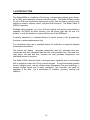
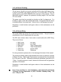
2.0 Benefits, Features, Specifications
BENEFITS
The Model 2450e uses LONWORKS® Technology that is
the latest in microprocessor capability, giving the user
the highest level of application flexibility. A large
illuminated graphics screen, multiple inputs and very
easy setup with easy field upgrade characterize this
new technology. Water meters and sensors are
purchased separately.
• System run timer
• 5 Count down timers
Lubrication interval
Check CIP
Check Filters
Check Membranes
Check Sensor
• Four relays have user-selectable options:
pH/ORP setpoint;
Conductivity setpoint;
Temperature setpoint
Permeate flow setpoint;
Concentrate flow setpoint;
Percent recovery setpoint;
Auto-Flush
Various Alarms.
• 4-20 mA output for (-35L, select any four):
pH/ORP
conductivity
temperature
concentrate flow
permeate flow
percent recovery
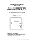
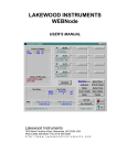
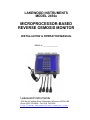
Figure 1: Model 2450e
Reverse Osmosis Monitor
FEATURES
•
•
•
•
•
•
Uses 2-electrode conductivity sensor with ¾
MNPT process connection
Uses differential pH sensor with ¾ MNPT
process connection.
pH input can be
configured for ORP sensor.
Two water meter inputs for Permeate and
Concentrate flow rates.
RS232 output for remote monitoring, control
and data acquisition (-RS2L).
Input for CIP lockout.
Includes Real Time Clock (-RTC).
SPECIFICATIONS
Inputs
Power
Sensor
Monitor
pH Range
pH Accuracy
pH Resolution
ORP Range
ORP Accuracy
ORP Resolution
Conductivity Range
Conductivity Accuracy
Conductivity Resolution
Deadband
Setpoints
Keypad
Display
Ambient Temperature
Enclosure
RATING
80-300 VAC
2 or 4-electrode Conductivity
pH or ORP differential
Temperature comp.
None, 500 NTC,
4K NTC
CIP switch
Dry contact
Water Meter Inputs Two, open collector type.
Outputs
Relays
4-20 mA
RS232
3 Amps @ 120 VAC
Two, isolated w/-35L
Requires Windows based PC w/RTC-RS2L
11
0-14 pH
± 0.05 pH
0.01 pH
-1000 to +1000 mV
± 5 mV
1 mV
0-100 or 0-1000 (with proper sensor)
±1 or ±10 µS (with proper sensor)
1 or 10 µS (with proper sensor)
Adjustable
Direct or Reverse
Numeric
Illuminated 128x64 pixel LCD
32-158°F (0-70°C)
NEMA 4X
ANSI/UL
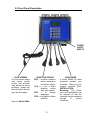
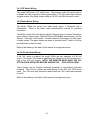
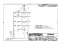
2.1 Ordering Information
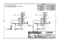
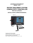
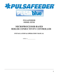
Figure 2: Model 2450e Installation Schematic
2450e
LONWORKS Technology-based Reverse Osmosis Monitor.
MONITOR OPTIONS (select no more than two, two -35L may be purchased)
-35L
Two 4-20 mA outputs (two -35L cards may be used for up to 4 outputs).
-RS2L
Communications node with the LRWS program.
SENSOR OPTIONS
1104593
pH High Purity sensor, ¼ inch NPT flow cell
520-4-7I-10-STD
pH sensor 0-14 pH, ¾ inch NPT
530-4-7I-10
ORP sensor, ¾ inch NPT
540K0.1-4-10I-10-TC500 Conductivity Sensor 0-10 µS, ¾ inch NPT
540K.1-4-10I-10-TC500 Conductivity Sensor 0-100 µS, ¾ inch NPT
543-L-4-8I-10-STD
Conductivity Sensor 0-1000 µS, 1 inch NPT
543-M-4-8I-10-STD
Conductivity Sensor 500-100,000 µS, 1 inch NPT
AUTOTROL TURBINE WATER METER OPTIONS
1TM-NPT 1 inch turbine water meter with brass pipe thread adapters.
1TM-ESW 1 inch turbine water meter with PVC solvent weld adapters.
2TM-NPT 2 inch turbine water meter with brass pipe thread adapters.
2TM-ESW 2 inch turbine water meter with PVC solvent weld adapters.
49C25
25 ft cable for turbine meters.
49C50
50 ft cable for turbine meters.
SOFTWARE AND EXTERNAL MODEM OPTIONS
LRWS
Windows-based registered software for computer to communicate with 2000 Series
Controllers.
WEBNode IP/TCP device for use with 2000 series controllers.
EZWEB
Wireless internet interface for use with WEBNode and 2000 series controllers
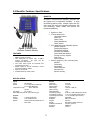
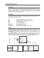
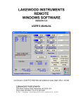
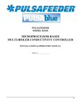
2.2 Front Panel Description
POWER
ON/OFF
SWITCH
LOCK SCREWS
The lock screws keeps
your circuit boards
secure and provides
easy access for wiring
and setup. Simply turn
the lock screw and pull
open the front panel.
16-BUTTON KEYPAD
ENT = for Menu selection
and/or acceptance
of selected values.
CLR = to exit a Menu
selection
and/or
skip input options.
DSP
=
to
change
languages.
PRO = to program a Menu
selection.
Figure 3: Model 2450e
13
ENCLOSURE
A sturdy NEMA 4X rated
enclosure protects your
controller. Make sure it is
properly mounted (SEE:
INSTALLATION;
Mounting). The power
cord and receptacles can
be removed so that the
controller can be hardwired
through
½"
conduit
knockouts.
3.0 Unpacking, Mounting and Installation
3.1 Unpacking
Inspect the shipping carton for obvious external damage. Note on the carrier's
bill-of-lading the extent of the damage, if any, and notify the carrier. Save the
shipping carton until your Model 2450e controller is started up.
If shipping damage has occurred, call the Lakewood Instruments
Customer Service Department at (800) 228-0839 and return the controller
to the factory in the original carton.
3.2 Mounting the Enclosure
The Model 2450e is supplied with four mounting feet. The Model 2450e can be
mounted to a panel or to a flat non-vibrating wall.
•
•
•
•
•
•
•
•
Attach the four mounting feet to the back of the controller enclosure.
Install on smooth surface to prevent stress on the mounting feet.
Do not install on vibrating wall.
If enclosure is installed in corrosive environments, consider purging.
Dimensions indicated as inches (millimeters).
The enclosure material is PVC.
Use #10 mounting screws (4).
Avoid drilling or punching additional holes in the controller enclosure.
Damage incurred as a result of any alteration to the enclosure is not
covered under the Lakewood Instruments product warranty.
The dimensions of the enclosure in inches are:
The model 2450e has a shipping weight of about 8 lbs.
14
3.3 Sensor Installation
3.3.1 Conductivity Sensor Plumbing
The Conductivity sensor may be mounted in any position as long as the
sensor tip is fully immersed in the active process water stream. Avoid
connections in “dead leg” sections of pipe. An air pocket around the electrode
tips will cause erroneous readings. The sensor electrodes should be in direct
contact with the process flow (see DWG #04259 in the back of this manual).
Note: Remember to install isolation and bypass valves so that maintenance
can be performed.
3.3.2 Conductivity Sensor Wiring
The model 2450e will accept the model 540K.1, the model 540K.01, the model
543M, the model 543L, and the model 543LL conductivity sensors. The
conductivity sensor is wired directly to the I/O board inside the controller.
The 543 series sensors have 6 wires. They are as follows:
•
•
•
•
•
•
Black wire
Red wire
White wire
Green wire
Black wire
Black wire
Electrode
Electrode
Electrode
Electrode
Temp compensation
Temp compensation
The 540 series sensors have 4 wires. They are as follows:
•
•
•
•
Black wire
Red wire
White wire
Green wire
Outer Electrode
Center Electrode
Temp compensation
Temp compensation
For wiring instructions please refer to the drawings at the back of this manual.
The maximum allowed cable length between the sensor tip and the controller
is twenty (20) feet. Cable length of conductivity sensors is measured from the
electrode tips to the end of the wire. Lakewood Instruments guarantees
operation up to 20 feet. If a cable extension is used, Lakewood Instruments
will not guarantee operation of the sensor.
15
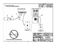
3.3.3 pH Sensor Plumbing
The pH sensor should be mounted vertically with the glass bulb facing down.
It may be mounted at an angle as long as it is no more than 75° from the
vertical position (see DWG #1240520-1a in the back of this manual). Due to
the bubble position, however, the preferred mounting angle is no more than
45° from vertical.
The sensor must also be mounted in a location so that it is always wet. If is
located in a pipe or tank with variable fluid levels, it is important that the sensor
is installed where it can remain wet. Failure to do so will damage the sensor.
Remember to install isolation and bypass valves so that maintenance can be
performed.
3.3.4 pH Sensor Wiring
The model 2450e will accept the model 520 pH sensor. The pH sensor is
wired directly to the I/O board inside the controller.
The 520 series sensors have 4 wires and a coaxial cable with a BNC fitting.
They are as follows:
•
•
•
•
•
•
BNC center
BNC Shield
Black wire
Red wire
White wire
Green wire
pH signal
(not used)
Temp Compensation
Temp compensation
Solution GND
Reference
For wiring instructions please refer to the drawings at the back of this manual.
The maximum allowed cable length between the sensor tip and the controller
is fifteen (15) feet. Cable length of pH sensors is measured from the electrode
tip to the end of the wire. Lakewood Instruments guarantees operation up to
15 feet. If a cable extension is used, Lakewood Instruments will not guarantee
operation of the sensor.
Remember to install isolation and bypass valves so that maintenance can be
performed.
If you have questions or need assistance, call Lakewood Instruments
Technical Service Department at (800) 228-0839, Monday-Friday, 7:30
a.m. - 5:00 p.m. CST.
16
3.4 Electrical Installation
3.4.1 Incoming Power 115/230 VAC
The Model 2450e can be powered from either 115 VAC or 230 VAC at 50/60 Hz.
The Model 2450e controller comes with a power cord and receptacles. The power
cord and receptacles are rated for 115VAC. If the controller will be powered by 230
VAC, the power cord and receptacles will need to be removed and the incoming
power and the relay outputs will need to be hard-wired.
The incoming power is connected to terminal block TA at the bottom right corner of
the power supply board. There is a hot or line input (terminal 4), a neutral input
(terminals 2 and 3) and an earth ground input (terminal 1). The hot is wired to the
fuse holder located on the bottom of the enclosure. The neutrals are wired directly
to terminals 2 and 3 of terminal block TA. Refer to the drawing in the back of this
manual for wiring instructions.
3.4.2 Relay Wiring
The relay outputs are of the same voltage as the power input. Ensure that the
devices that are to be connected to the relay outputs are of the same voltage rating
or damage will occur.
The relay outputs are wired to the receptacles. The receptacle on the far left is
relay #1 and the receptacle on the far right is relay #4. On the power supply board,
relay #4 is on the far left and relay #1 is on the far right. If 115 VAC is used simply
plug your devices into the molded receptacles. If 230 VAC is used, remove the
receptacles and hard-wire your devices to the relay outputs.
Relay #1 and #2 have both a normally open and normally closed contact. This is
designed for use with motorized valves. The normally open (NO) contact is
connected to the open connection of the valve and the normally closed (NC)
contact is connected to the close connection of the valve. The other two relays
only have a normally open contact. Each relay output requires a neutral connection
and an earth ground connection for proper operation.
Refer to the drawing in the back of this manual for wiring instructions.
WARNING! DO NOT PLUG IN CHEMICAL PUMPS THAT ARE LARGER THAN
1/6 HORSEPOWER.
THE CONTROL RELAYS ARE INTENDED FOR
ELECTRONIC OR SMALL MOTOR-DRIVEN CHEMICAL PUMPS. LARGER
PUMPS REQUIRE THE -HR OPTION WITH 25-AMP-RATED INTERPOSING
RELAYS.
CONTACT LAKEWOOD INSTRUMENTS FOR SPECIAL
INSTRUCTIONS.
17
3.4.3 CIP Switch Wiring
The model 2450e has a CIP switch input. The purpose of the CIP switch input is
to disable the relay outputs for cleaning the system. The CIP switch input requires
a digital contact. Any digital contact rated for 24 VDC and 500 mA may be used.
3.4.4 Water Meters Wiring
The Model 2450e will accept two water meter inputs; a Permeate and a
Concentrate. Refer to the water meter manufacturer’s manual for plumbing
information.
The 2450e monitor will work directly with the following types of meters: Seametrics
open collector output meters, Signet 2535 and 2540 paddle wheel meters, and the
Autotrol 1 inch and 2 inch meters. Contact Lakewood Instruments for other types
of water meters. The water meters are wired to terminal block P1 which is the top
terminal block on the I/O board.
Refer to the drawing in the back of this manual for wiring instructions.
3.4.5 4-20 mA Output Wiring
If the -35L option is ordered, the model 2450e has two channels of 4-20 mA
output. The model -35L2 adds an additional two channels of 4-20 mA output for a
total of four 4-20 mA outputs. NOTE: THE MONITOR MUST HAVE THE -35L
OPTION CARD INSTALLED BEFORE ADDING THE -35L2 OPTION CARD.
These outputs can be isolated (externally powered) or non-isolated (internally
powered). The 4-20 mA outputs are wired directly to the -35L and -35L2 option
cards. The -35L card uses channels A and B while the -35L2 card uses channels
C and D.
Refer to the drawing in the back of this manual for wiring instructions.
18
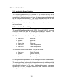
4.0Functional Overview
4.1 Display
The model 2450e uses an illuminated 128x64-pixel LCD digital display for ease of
viewing. It has multiple lines to display information such as the pH reading,
conductivity reading, alarms, relay status, relay configuration, clock, flow totals for
both water meters, and menu selections.
4.2 Keypad
The model 2450e uses a 16-key numeric keypad for ease of programming. The
keys have the following functions:
ENT
CLR
PRO
DSP
UP arrow
DOWN arrow
Number keys
To accept a setting or to enter a screen.
To exit a screen or to access the main menu.
To calibrate the controller.
To change languages.
To move about in the menu.
To move about in a menu.
To input a value or to select a menu item.
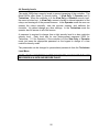
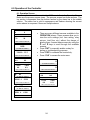
4.3 Menu
The model 2450e is programmed and calibrated by the use of a menu. The
complete Main Menu has 8 available options that can be accessed in the
Technician Level. However, a list of only six options can be viewed at one time.
Use the Ï and Ð keys to scroll through the options. As an introduction, here is a
graphic overview of the first level of each option in the Main Menu to see how it
operates. Complete details of each option are provided later in this manual.
1
2
3
4
5
6
7
1
PERM
0
CONC
0
{Alarms Flashing}
pH
5.76
COND
90
MAIN MENU
=============
OPERATION
RELAYS
ALARMS
FLOW METERS
4-20 MA OUTPUTS
SYSTEM SETUP
CLOCK
2
3
4
WHICH RELAY?
WHICH INPUT DEVICE?
WHICH INPUT DEVICE?
============
============
============
1 RLY1
2 RLY2
3 RLY3
4 RLY4
1 pH/ORP
2 COND
3 TEMP
4 PERM
5 CONC
6. FEED
7. % REC
1 PERM
2 CONC
3. FEED
PRO: CALIB; ENT=RELAYS
6
7
SYSTEM SETUP
WED
28 AUG 96
============
1 PROCESS PARAMETERS
2 INITIALIZATION
3 SECURITY
4 SOFTWARE VERSION
5 TIMER
6 DIAGNOSTICS
7 COMMUNICATIONS
05:42:40
PRO: CHANGE; CLR=EXIT
19
4.4 Security Levels
The model 2450e has a security levels to prevent tampering of the controller. The
Model 2450e offers three (3) security levels: 1) View Only, 2) Operator and 3)
Technician. When the controller is in the View Only or Operator security level,
the menu is locked out. In View Only, access is limited to manual operation of the
relays, and viewing all of the process screens. In the Operator mode the user can
operate the relays manually, view the process screens, and calibrate the
controller. He cannot change any other settings. In the Technician mode the
operator has full access to all of the menus.
A password is required to change from a tight security level to a less restrictive
security level. Each level has its own factory-preset password (2222 for
Technician, 1111 for Operator). If the controller is in the View Only or Operator
mode just press the appropriate password on the keypad to change to a less
restrictive security mode.
The passwords can be changed to personalized passwords from the Technician
Level Menu.
NOTE: IF YOU USE PERSONALIZED PASSWORDS, MAKE SURE THEY ARE
RECORDED IN A SAFE AND SECURE PLACE.
20
5.0 Starting Up the Monitor
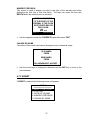
5.1 Initial Power Up
Upon initial power up you will notice the Monitor will display:
SERIES 2000
REVERSE OSMOSIS
MONITOR
PRESS ANY KEY
This indicates that power has been applied to the Monitor and no one has touched
the keypad. This will also occur anytime there is a power outage and power
has been returned to the Monitor.
•
•
•
Press any key on the keypad and you will see the Operation Screen on the
screen.
Press CLR on the keypad and you will see the Main Menu on the screen.
Use the Ï and Ð arrow keys to move through the menu.
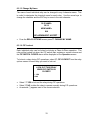
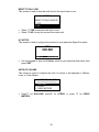
5.2 Initialization
Initialization restores the factory default settings to the controller. The whole
controller can be initialized or just the calibration. It is suggested that you initialize
the whole controller before you program the controller. This will clear any random
settings that may be in the controller.
To initialize the whole controller:
•
•
•
From the Main Menu, press ”6” SYSTEM SETUP.
Press ”2” INITIALIZATION.
Press ”2” WHOLE CONTROLLER. A warning will appear on the screen (see
below). Press ”1” to proceed, ”2” to cancel.
WARNING:
THIS OPTION REQUIRES
RE-CALIBRATION AND REPROGRAMMING!
PROCEED?
1 YES
2 NO
21
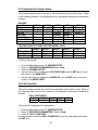
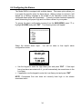
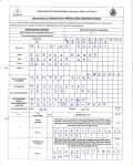
5.3 Conductivity Preamp Setup
The internal preamp must be set up for the conductivity sensor that is used. Refer
to the following tables for the preamp setup for Lakewood Instruments conductivity
sensors.
RANGES
Cond Range
1-10
10-100
100-500
100-1000
1000-10000
10000-100000
540 K.1
Range 4
Range 3
-
540 K.01
Range 3
-
543M
Range 3
Range 2
Range 2
Range 1
Range 0
543L
Range 2
Range 2
Range 2
Range 2
-
PREAMPLIFIER SETTINGS FOR THE MODEL 2450e
Range 0 Range 1 Range 2 Range 3
Voltage Gain 100
10
10
10
Sample R
20
20
200
2K
Drive. Freq.
500 Hz
500 Hz
500 Hz
500 Hz
543LL
Range 2
Range 2
Range 2
-
Range 4
1
2K
30 Hz
To set up the preamp:
•
•
•
•
•
From the Main Menu press ”6” SYSTEM SETUP.
Press ”1” PROCESS PARAMETERS Select Cond.
Press "2" PREAMP SETUP.
Use the arrow keys to change the VOLTAGE GAIN, use the ENT key to move
the cursor to the SAMPLE R.
Use the arrow keys to change the SAMPLE R, use the ENT key to move the
cursor to the DRIVE FREQ.
5.4 Cell Constant
The cell constant must be set up for the conductivity sensor that is used. Refer to
the following table for the cell constants for Lakewood Instruments conductivity
sensors.
CELL CONSTANTS
540 K.1 540 K.01 543M 543L 543LL
0.1
0.01
0.30
0.03
0.07
To set up the Temperature Compensation:
• From the Main Menu press ”7” SYSTEM SETUP.
• Press ”1” PROCESS PARAMETERS. Select Cond.
• Press "4" CELL CONSTANT.
Use the keypad to enter the CELL CONSTANT as per the table above and press
the ENT key.
22
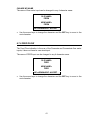
5.5 Temperature Compensation
The model 2450e has a single temperature compensator input. This input is used
to display the temperature of the permeate flow as well as to temperature
compensate the pH and Conductivity readings. The input can come from either
the pH or the conductivity sensor depending on which sensor is wired to the
temperature compensation input. Set up the temperature compensation for the
temperature compensator value of the sensor that is wired to the temperature
compensation input. NOTE: If the temperature compensator if the pH sensor
is used, the temperature that is displayed will be the FEED WATER
temperature NOT the permeate temperature.
The model 520 series pH sensor has a 10K PTC temperature compensator.
Refer to the following table for the temp compensators for Lakewood Instruments
conductivity sensors.
TEMP COMPENSATION
540 K.1
540 K.01
543M
500 NTC 500 NTC 4K NTC
543L
4K NTC
543LL
1K PTC
To set up the temperature compensation:
•
•
•
•
•
From the Main Menu press ”6” SYSTEM SETUP.
Press ”1” PROCESS PARAMETERS.
Press “3” TEMP
Press “2” TEMP COMPENSATION
Select the value of your temperature compensator. Press “ENT”.
23
6.0 Operation of the Controller
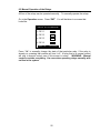
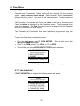
6.1 Operation Screen
The screen that is used the most in the 2450e controller is the Operation Screen.
Below are the process screen views. The process screen has three sections. The
top section is separated from the bottom section by the alarm bar in the middle
section. The alarm bar is solid in appearance and flashes showing the current
active alarms in sequence if there are multiple alarms.
PERM
CONC
0
0
{ALARMS FLASHING}
pH
•
COND
5.76
90
PRO: CALIB; ENT=RELAYS
RO MACHINE RUN TIME
0:00
{ALARMS FLASHING}
TEMP = 25 ºC
PRO=CALIB; ENT=RELAYS
PERM
0.0
•
•
CONC
TOTAL PERM=
0.0
{ALARMS FLASHING}
COND
%REC
0.0
0%
PRO: CALIB; ENT=RELAYS
µS
•
There are many different screens available in the
OPERATION screen. These screens allow you to
view the unit’s settings (incl. time setting, relay
set-ups, total flow, etc.) without the danger of
altering them. Access these screens by using the
Ï and Ð keys to scroll through the available
screens.
Press “ENT” to manually enable a relay for
testing or troubleshooting purposes.
Press “PRO” to calibrate the conductivity.
Press “CLR” to access the main menu.
0
{ALARMS FLASHING}
TOTAL FEED=
0
PRO=CALIB; ENT=RELAYS
PERM
89
{ALARMS FLASHING}
0.0
CONC
0.0
{ALARMS FLASHING}
PERM 0
GPM
PRO=CALIB; ENT=RELAYS
COND
%REC
0.0
0%
PRO: CALIB; ENT=RELAYS
pH
5.58
{ALARMS FLASHING}
FEED 0
GPM
PRO=CALIB; ENT=RELAYS
24
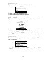
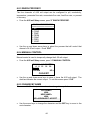
6.2 Manual Operation of the Relays
All four of the relays can be operated manually. To manually operate the relays:
Go to the Operation screen. Press “ENT”. You will be taken to a screen that
looks like:
RELAY AUTO-MANUAL
(1)
RLY1
(2)
RLY2
(3)
RLY3
(4)
RLY4
Press 1-4;
CLR=EXIT
PRE 1-4; CL
EXIT
Press “1-4“ to manually change the state of that particular relay. If the relay is
already on, pressing that number will turn it off. A relay that is in manual control
will stay in manual control even if this screen is exited.
WARNING: Manual
control overrides everything. Use care when operating relays manually with
no flow in the system.
25
6.3 Calibration of Conductivity and pH
6.3.1 CALIBRATION of CONDUCTIVITY
The conductivity requires periodic calibration. Calibration is usually required after
cleaning the sensor.
Calibration should always be performed with the sensor in the piping assembly
with good flow past the sensor. It is necessary to have an accurate reading of the
water to properly calibrate the controller. A hand-held conductivity meter that tests
the sample works well for this purpose. Buffers should not be used for calibration
purposes.
The model 2450e controller uses a single point calibration. A two point calibration
is not necessary if using a Lakewood Instruments conductivity sensor.
•
•
•
•
•
•
Ensure that the monitor is operating with good flow past the sensor.
Take a sample of the water and measure with a hand-held conductivity tester.
From the Operation screen, press “PRO” to enter the calibration screens.
Press “2” COND
Use the keypad to input the conductivity reading from the hand-held. Press
“ENT”.
Take another hand-held sample to verify calibration.
6.3.2 CALIBRATION OF pH/ORP
The model 2450e monitor uses a single point calibration. A two point calibration is
not necessary if using a Lakewood Instruments pH sensor because all Lakewood
pH sensors have a slope of 59.14 mv per pH. If the slope has changed enough to
require a two point calibration then the sensor should be cleaned or replaced.
We recommend that the pH calibrations only be performed with the sensor
mounted as it will be used in the system. Buffers can be used to check
calibrations but should not be used for calibration purposes.
It is necessary to have an accurate reading of the process water to properly
calibrate the controller. A hand-held meter that tests the sample is best. Once
you have obtained a reading, immediately enter the value into the controller. In
the operation screen:
• Press PRO.
• Select pH.
• Select either ZERO or SPAN (see below).
• Use the number keys to enter the value, and then press ENT.
• Take a second sample with a hand-held pH meter and confirm the reading on
the display.
26
6.3.2.1 ZERO or SPAN?
The model 2450e monitor is capable of performing a two point calibration using
both the ZERO and SPAN calibrations. The operator must pick either ZERO or
SPAN to perform a single point calibration. There are error messages associated
with calibration points (see below). If an improper calibration is being performed
an error message may appear.
To perform a good single point calibration the ZERO calibration should be
performed at a lower pH than the SPAN calibration. A good rule of thumb is to
perform a ZERO calibration if the measured pH is less than 7.00 pH and use the
SPAN if the measured pH is greater than 7.00 pH.
6.3.2.2 CALIBRATION ERROR MESSAGES
The model 2450e will display calibration error messages to alert the operator of a
possible calibration error. “THE SPAN AND ZERO VALUES SHOULD BE AT
LEAST TWO pH APART” error message will occur if the zero and/or the span
calibrations are performed within two pH of each other. If you receive this error
message, initialize the calibration and repeat the calibration using the rule of
thumb above.
The “pH DEVIATION GREATER THAN 1.5 FROM DEFAULT CHK PROBECABLE-SOL’N” error message will occur if the calibration value is more than 1.5
pH away from the value the controller thinks the pH should be based on the signal
input from the sensor. This could indicate a failed sensor or interference in the
system. If you receive this message perform a calibration check using buffer
solutions.
6.3.2.3 CALIBRATION CHECK OF pH or ORP IN BUFFER SOLUTIONS
To check the calibration of the sensor in buffer solutions, the sensor must be held
in the center of a buffer solution. Perform the calibration check as follows:
•
•
•
•
•
•
Initialize the calibrations.
Shut down the system and remove the pH or ORP sensor.
Place the sensor into the buffer solutions.
Verify calibrations in at least two buffer solutions at least 2 pH or 200 mV
apart.
Re-install the sensor into the plumbing.
Perform a single point calibration if necessary.
27
6.4 Main Menu
The MAIN MENU of the 2450e looks like this:
MAIN MENU
=====================
1 OPERATION
2 RELAYS
3 ALARMS
4 FLOW METERS
5 4-20 MA OUTPUTS
6 SYSTEM SETUP
7 CLOCK
The MAIN MENU can be accessed from the OPERATION screen by pressing
“CLR”. If “CLR” is pressed and the MAIN MENU does not appear, the controller is
probably in the VIEW ONLY or OPERATOR security mode. If the controller is in
the VIEW ONLY or OPERATOR security mode, enter the TECHNICIAN security
password to be able to access the MAIN MENU.
To move about in the menu screen use the Ï and Ð keys to highlight the desired
option and press “ENT” or simply press the number key for the desired option.
Use the “ENT” key to accept a setting or to enter a screen. Use the “CLR” key to
reject a setting or to exit a screen. From anywhere in the menu, pressing “CLR”
will take you one step closer to the MAIN MENU.
Certain menu items are only visible if certain conditions apply, such as:
option cards are installed, or other parameters are configured. If a menu
item does not appear in the menu it most likely means that the option is not
installed or configured.
Each of the MAIN MENU options is discussed in detail later in this manual.
28
6.5 Configuring the Relays
To access the relay configuration screen from the MAIN MENU, press “2” or
highlight RELAYS and press “ENT”. The following screen will appear.
WHICH RELAY?
============
1 RLY1
2 RLY2
3 RLY3
4 RLY4
Select the relay that you want to program.
6.5.1 RELAY OPTION SCREEN
Below is the RELAY OPTIONS screen. The asterisk (*) next to one of the options
tells you how that relay is configured.
There are multiple methods that the relays can be configured to operate. When a
relay is selected for programming the following screen will appear.
RELAY OPTIONS
========================
1 DISABLED
2 *SETPOINT CONTROL
3 AUTO FLUSH
4 ALARM RELAY
5 CHANGE MY NAME
6 CIP LOCKOUT
6.5.1.1 Disabled
The relays can be disabled.
automatically.
When a relay is disabled, it will not energize
From the RELAY OPTIONS screen press “1” Disabled to disable the relay.
29
6.5.1.2 SETPOINT CONTROL
The relays can be configured to operate based on a setpoint from any of the inputs
such as: pH or ORP, CONDUCTIVITY, TEMPERATURE, PERMEATE
FLOWRATE, CONCENTRATE FLOWRATE, FEED FLOWRATE, and PERCENT
OF RECOVERY.
When setpoint control is selected the following screen will appear.
WHICH INPUT DEVICE?
========================
1 pH
2 *COND
3 TEMP
4 PERM
5 CONC
6 FEED
7 %REC
Select the desired input for setpoint control. You will be taken to a screen that lists
that input with the instruction to “PRESS ANY KEY”. Once you press any key on
the keypad, the SETPOINT OPTIONS screen will appear:
SETPOINT OPTIONS
========================
1 SETPOINT VALUES
2 SETPOINT DIRECTION
To program the setpoint, select “1” SETPOINT VALUES.
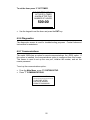
To set the direction of operation, select “2” SETPOINT DIRECTION.
6.5.1.2.1 SETPOINT
In the SETPOINT VALUES screen you will set the SETPOINT, the DEADBAND
and the TIMEOUT alarm.
SETPOINT=
0 µS
DEADBAND=
0 µS
PRO:”+/-“
ENT:ACCEPT
The SETPOINT is the input device value that you are trying to maintain. Check
with your water treatment engineer to determine the setpoints for your system
needs.
•
Use the keypad to enter the setpoint and press ”ENT”. You will automatically
be moved down to the deadband.
30
6.5.1.2.2 DEADBAND
After the setpoint is established, the relay's deadband must also be set.
"Deadband" refers to the amount of reading above and below the setpoint—a
range within which the controller will not react. Due to continuous fluctuations in
the input level, it is necessary to have this deadband range or stable readings will
be difficult to obtain. The Deadband should be a small percentage of the setpoint.
Half the deadband amount will be automatically put above the setpoint, and the
other half below it.
For example, a Conductivity setpoint of 100 µS with a deadband of 10 µS would
result in the relay turning on at 105 µS and turning off at 95 µS.
•
Use the keypad numbers to enter the deadband value and press ”ENT”.
You will automatically be switched to the TIMEOUT alarm screen.
6.5.1.2.3 TIMEOUT
The TIMEOUT alarm is designed to notify the operator of a problem in the system
such as, a pump has lost its prime or there is no chemical in the drum. It will also
protect the system from overfeeding chemical when the indicated input does not
display a change in actual reading. The TIMEOUT function will display a visual
alarm on the display and it will turn off the relay. If a relay is configured as an
alarm relay, the TIMEOUT alarm will energize the alarm relay.
•
Use the keypad to enter the time in hours and minutes before this alarm will
appear and press ”ENT”. Maximum setting is 17 hours and 59 minutes. To
disable this function, set the OVERFEED time to 0:00.
6.5.1.2.4 SETPOINT DIRECTION
After configuring the SETPOINT, the DEADBAND, and the TIMEOUT alarm, the
monitor will automatically move to the SETPOINT DIRECTION screen. To set up
to operate the relay on a rising reading select DIRECT to activate above the
setpoint. To set up to operate on a falling reading select REVERSE to activate
below the setpoint.
SETPOINT DIRECTION
=====================
1 *DIRECT
2 REVERSE
•
Select “1” DIRECT to turn on the relay when the reading rises above the
setpoint, or select “2” REVERSE to turn on the relay when the reading falls
below the setpoint.
31
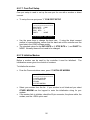
6.5.1.3 AUTO FLUSH
The AUTO FLUSH feature is designed to turn on a relay for a user specified
amount of time after a user specified amount of machine runtime. From the
RELAY OPTIONS screen select “3” AUTO FLUSH
EVERY (HRS:MINS)
0:00
OF RUNTIME, FLUSH FOR
0:00
(MINS:SECS)
PRO:”+/-“
ENT:ACCEPT
•
•
Use the keypad to enter an amount of machine runtime, in hours and
minutes, then press “ENT”.
Use the keypad to enter an amount of flush time, in minutes and seconds,
then press “ENT”.
6.5.1.4 Alarm Relay
The relays can be configured as alarm relays. The alarms that will cause the relay
to activate are selectable from the controller alarms or from any node input alarms.
The controller alarms include: High and Low pH, High Cond, High Temp, High and
Low Perm flow rate, High and Low Feed flow rate, High %REC, Lubrication
Interval, Check CIP, Check Filters, Check Membranes, Check Sensor, Cond:
Fouled Sensor, Shorted TC, Opened TC, High REF Impedance, Broken Glass,
High REF Voltage, Low REF Voltage, CIP Switch Closed, and Relay Time
Exceeded alarms.
•
From the RELAY OPTIONS screen press”4” ALARM RELAY. The controller
will respond with the following screen.
WHICH ALARMS?
====================
1 pH: HIGH ALARM
2 pH: LOW ALARM
3 COND: HIGH ALARM
4 TEMP: HIGH ALARM
5 PERM: HIGH ALARM
6 PERM: LOW ALARM
•
Only 6 alarms are shown at a time on the screen, use the arrow keys to scroll
up and down the choices and select the alarms by pressing “ENT” when the
desired alarm is highlighted. An asterisk (*) will appear next to all alarms that
are currently selected.
32
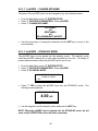
6.5.1.5 Change My Name
The name of each individual relay can be changed to any 4-character name. This
is useful to designate the chemical name for each relay. Use the arrow keys to
change the character and the ENT key to move to the next character.
OLD NAME=
RLY2
NEW NAME=
INH
<UP><DOWN>ENT: ACCEPT
•
From the RELAY OPTIONS screen press”5” CHANGE MY NAME.
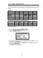
6.5.1.6 CIP Lockout
Each individual relay can be locked out during a Clean-In-Place operation. The
relay will be locked out when the CIP switch input registers a contact closure and
the CIP SWITCH CLOSED alarm will be displayed on the Operation screen.
To lockout a relay during CIP operations, select “6” CIP LOCKOUT from the relay
options screen for each relay you want to lock out.
LOCK OUT THIS RELAY
WHEN CIP SWITCH IS
CLOSED?
1 YES
2*NO
•
•
•
Select “1” YES to lock out the relay during CIP operations.
Select “2” NO to allow the relay to operate normally during CIP operations.
An asterisk (*) appears next to the current selection.
33
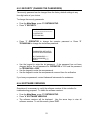
6.6 Configuring the Alarms
The Model 2450e is equipped with multiple alarms. This menu option allows you
to program the specific values for these alarms. When an alarm is received, it will
appear as a flashing message in the middle of the Operation screen and any
configured alarm relays will be activated. Consult your water treatment specialist
when determining the proper High and Low Alarm values for your system.
To access the alarm configuration screens from the MAIN MENU, press “3” or
highlight ALARMS and press “ENT”. The following screen will appear.
WHICH INPUT DEVICE?
========================
1 pH
2 COND
3 TEMP
4 PERM
5 CONC
6 FEED
7 %REC
Select the desired alarm input.
configuration screen:
You will be taken to that input’s alarm
HIGH ALARM=
10.00 pH
LOW ALARM=
7.00 pH
PRO:”+/-“
•
•
ENT:ACCEPT
Use the keypad to enter the High Alarm point and press ”ENT”. If that input
has a low alarm associated with it, you will automatically be moved down to the
Low Alarm.
If applicable, use the keypad to enter the Low Alarm point and press ”ENT”.
NOTE: Concentrate flow rate does not currently have high or low alarms
associated with it.
34
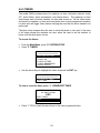
6.7 Flow Meters
The 2450e series controllers include two flow meter inputs for use as the
Permeate and Concentrate. These inputs will work directly with the following
types of open collector output meters: Data Industrial, Signet paddle wheel
meters, and the Autotrol 1 inch and 2 inch turbine meters. Contact Lakewood
Instruments for other types of water meters.
The Permeate, Concentrate, and Feed flow rates as well as the Permeate and
Feed flow totals are displayed on the Operation screen. The Concentrate flow
total is not displayed. The Feed flow meter input is the sum of both the Permeate
and the Concentrate flow meter inputs.
The Permeate and Concentrate flow meter inputs are programmed using the
following procedures.
To get to the flow meter configuration screen:
•
•
•
From the main menu, press”4” FLOW METERS. This will take you to the
WHICH FLOW METER screen.
Press”1” for PERM, press”2” for CONC, or “3” for FEED.
This will take you to the WATER METER TYPES screen as shown.
WATER METER TYPES
=================
1 DATA INDUSTRIAL
2 SIGNET
3 *AUTOTROL TURB 1 IN.
4 AUTOTROL TURB 2 IN.
•
Use the keypad to select the type of flow meter that you are using.
6.7.1 Data Industrial
If DATA INDUSTRIAL is selected the following screen will appear:
1
2
3
4
5
PERM
=================
RESET TOTAL FLOW
SLOPE AND OFFSET
UNITS OF VOLUME
NUMERIC PRECISION
CHANGE MY NAME
35
RESET TOTAL FLOW
This screen is used to reset the total flow for this input back to zero.
PERM
RESET TOTAL COUNTS?
1 YES
2 NO
•
•
Select “1” YES to reset the total flow to zero
Select “2” NO to keep the current flow meter total.
SLOPE and OFFSET
This screen is used to configure the monitor for your particular Data Industrial flow
meter.
PERM
SLOPE VALUE (K) =
#. # # #
OFFSET =
0.0000
PRO:”+/-“
•
•
ENT:ACCEPT
Use the keypad to enter the SLOPE or K factor value for your particular water
meter then press ”ENT”.
Use the keypad to enter the OFFSET value for your particular water meter then
press ”ENT”.
UNITS OF VOLUME
This screen is used to configure the units of volume to be displayed to Gallons,
Liters, or Cubic Meters.
UNITS OF VOLUME
=================
1 *GALLONS
2 LITERS
3 CUBIC METERS
•
Press”1” for GALLONS, press”2” for LITERS, or press “3” for CUBIC
METERS.
36
NUMERIC PRECISION
This screen is used to display one digit to the right of the decimal point when
displaying the flow rate of this flow meter. The user can select the flow rate
BELOW which the decimal point is activated.
DISPLAY ONE DIGIT
TO THE RIGHT OF THE
DECIMAL IF THE FLOW
RATE DROPS BELOW
THIS VALUE:
20 GAL
PRO:”+/-“
•
ENT:ACCEPT
Use the keypad to enter the FLOWRATE value then press ”ENT”.
CHANGE MY NAME
The name of flow meter input can be changed to any 4-character name.
OLD NAME=
PERM
NEW NAME=
PERM
<UP><DOWN>ENT: ACCEPT
•
Use the arrow keys to change the character and the ENT key to move to the
next character.
6.7.2 SIGNET
If SIGNET is selected the following screen will appear:
1
2
3
4
5
PERM
=================
RESET TOTAL FLOW
K FACTOR
UNITS OF VOLUME
NUMERIC PRECISION
CHANGE MY NAME
37
RESET TOTAL FLOW
This screen is used to reset the total flow for this input back to zero.
PERM
RESET TOTAL COUNTS?
1 YES
2 NO
•
•
Select “1” YES to reset the total flow to zero
Select “2” NO to keep the current flow meter total.
K FACTOR
This screen is used to configure the monitor for your particular Signet flow meter.
PERM
000.000
PRO:”+/-“
•
ENT:ACCEPT
Use the keypad to enter the K factor value for your particular flow meter then
press ”ENT”.
UNITS OF VOLUME
This screen is used to configure the units of volume to be displayed to Gallons,
Liters, or Cubic Meters.
UNITS OF VOLUME
=================
1 *GALLONS
2 LITERS
3 CUBIC METERS
•
Press”1” for GALLONS, press”2” for LITERS, or press “3” for CUBIC
METERS.
38
NUMERIC PRECISION
This screen is used to display one digit to the right of the decimal point when
displaying the flow rate of this flow meter. The user can select the flow rate
BELOW which the decimal point is activated.
DISPLAY ONE DIGIT
TO THE RIGHT OF THE
DECIMAL IF THE FLOW
RATE DROPS BELOW
THIS VALUE:
20 GAL
PRO:”+/-“
•
ENT:ACCEPT
Use the keypad to enter the FLOWRATE value then press ”ENT”.
CHANGE MY NAME
The name of flow meter input can be changed to any 4-character name.
OLD NAME=
PERM
NEW NAME=
PERM
<UP><DOWN>ENT: ACCEPT
•
Use the arrow keys to change the character and the ENT key to move to the
next character.
6.7.3 AUTOTROL TURBINES 1 INCH OR 2 INCH
If an AUTOTOL 1 IN. or 2 IN. turbine is selected the following screen will appear:
1
2
3
4
PERM
=================
RESET TOTAL FLOW
UNITS OF VOLUME
NUMERIC PRECISION
CHANGE MY NAME
39
RESET TOTAL FLOW
This screen is used to reset the total flow for this input back to zero.
PERM
RESET TOTAL COUNTS?
1 YES
2 NO
•
•
Select “1” YES to reset the total flow to zero
Select “2” NO to keep the current flow meter total.
UNITS OF VOLUME
This screen is used to configure the units of volume to be displayed to Gallons,
Liters, or Cubic Meters.
UNITS OF VOLUME
=================
1 *GALLONS
2 LITERS
3 CUBIC METERS
•
Press”1” for GALLONS, press”2” for LITERS, or press “3” for CUBIC
METERS.
NUMERIC PRECISION
This screen is used to display one digit to the right of the decimal point when
displaying the flow rate of this flow meter. The user can select the flow rate
BELOW which the decimal point is activated.
DISPLAY ONE DIGIT
TO THE RIGHT OF THE
DECIMAL IF THE FLOW
RATE DROPS BELOW
THIS VALUE:
20 GAL
PRO:”+/-“
•
ENT:ACCEPT
Use the keypad to enter the FLOWRATE value then press ”ENT”.
40
CHANGE MY NAME
The name of flow meter input can be changed to any 4-character name.
OLD NAME=
PERM
NEW NAME=
PERM
<UP><DOWN>ENT: ACCEPT
•
Use the arrow keys to change the character and the ENT key to move to the
next character.
6.7.4 FEED FLOW
The Feed Flow indication is the sum of the Permeate and Concentrate flow meter
inputs; it does not have its own wired input.
The name of FEED input can be changed to any 4-character name.
OLD NAME=
FEED
NEW NAME=
FEED
<UP><DOWN>ENT: ACCEPT
•
Use the arrow keys to change the character and the ENT key to move to the
next character.
41
6.8 4-20 mA OUTPUTS
The-35L option card adds two channels (channels A and B) of 4-20 mA output.
The addition of the -35L2 option card adds two additional 4-20 mA output channels
(channels C and D). The -35L option card must be installed in the monitor before
installing the -35L2 option card. NOTE: The -35L option card must be installed
for this menu selection to be functional.
The 4-20 mA output screens are used to set the range, calibrate the 4-20 mA
output, configure the output to a process, take manual control of the 4-20 mA
output, and change the name of the output.
To access the 4-20 mA output screens from the main menu:
•
•
From the main menu, press”5” 4-20 mA OUTPUTS. This will take you to the
OUTPUT CHANNEL selection screen.
Press”1” for CH A, press”2” for CH B, or “3” for CH C, or “4” for CH D.
4-20 MA OUTPUTS
=====================
1 420A
2 420B
3 420C
4 420D
Each channel is configured separately and when a channel is selected the
following screen will appear:
4-20A
=====================
1 SET 4-20 MA RANGE
2 CALIBRATE 4-20 MA
3 WHICH PROCESS?
4 MANUAL CONTROL
5 CHANGE MY NAME
NOTE: When configuring a channel of 4-20 mA output, the process
should be selected before setting the range.
42
6.8.1 SET the 4-20 mA RANGE
NOTE: When configuring a channel of 4-20 mA output, the process should be
selected before setting the range.
The range of the output channel should match the range of the device to which the
output is sent.
When SET 4-20 MA RANGE is selected the follow screen is displayed:
4 MA VALUE=
0.00 pH
20 MA VALUE=
14.00 pH
PRO:”+/-“
•
•
ENT:ACCEPT
Use the keypad to enter the 4 MA value then press ”ENT”.
Use the keypad to enter the 20 MA value then press ”ENT”.
6.8.2 CALIBRATE 4-20 mA
The 4-20 mA needs to be calibrated to the actual output to be accurate. A
milliamp meter is necessary to calibrate the 4-20 mA output. Connect the milliamp
meter in-line with one leg of the 4-20 mA output. Refer to the drawing in the back
of this manual for wiring instructions.
•
From the 4-20 mA Setup screen, press”2” CALIBRATE 4-20 MA. The screen
will show the current 4 mA reading:
MILLIAMPS=
4.00
PRO:”+/-“
•
ENT:ACCEPT
Use the keypad to enter the milliamp reading from the milliamp meter for the 4mA point. Press ”ENT”. The screen will show the current 20 mA reading:
MILLIAMPS=
4.00
MILLIAMPS=
20.00
PRO:”+/-“
•
ENT:ACCEPT
Use the keypad to enter the milliamp reading from the milliamp meter for the
20-mA point. Press ”ENT”.
43
6.8.3 WHICH PROCESS?
The four channels of 4-20 mA output can be configured to pH, conductivity,
temperature, permeate flow rate, concentrate flow rate, feed flow rate, or percent
of recovery.
•
From the 4-20 mA Setup screen, press”3” WHICH PROCESS?.
WHICH INPUT DEVICE?
=====================
1 *pH
2 COND
3 TEMP
4 PERM
5 CONC
6 FEED
7 %REC
•
Use the up and down arrow keys to select the process that will control that
channel of 4-20 mA output. Press ”ENT”.
6.8.4 MANUAL CONTROL
Manual control is used to temporarily change the 4-20 mA output.
•
From the 4-20 mA Setup screen, press ”4” MANUAL CONTROL.
MANUAL 4-20 CONTROL
4 8 12 16 20
BLANK
<-DOWN
UP->
CLR=EXIT
•
Use the up and down arrow keys to raise or lower the 4-20 mA output. The
dark bar indicates the current output. To exit this screen press ”CLR”.
6.8.5 CHANGE MY NAME
The name of 4-20 mA output channel can be changed to any 4-character name.
OLD NAME=
420A
NEW NAME=
420A
<UP><DOWN>ENT: ACCEPT
•
Use the arrow keys to change the character and the ENT key to move to the
next character.
44
6.9 SYSTEM SETUP
The system setup menu is used to set up the process parameters, initialize the
controller, check the software versions, change the security passwords, check the
diagnostics, set up the communications, set up the timers.
•
From the MAIN MENU, press ”6” SYSTEM SETUP.
SYSTEM SETUP
=====================
1 PROCESS PARAMETERS
2 INITIALIZATION
3 SECURITY
4 SOFTWARE VERSIONS
5 TIMERS
6 DIAGNOSTICS
7 COMMUNICATIONS
6.9.1 PROCESS PARAMETERS
There are sub-screens in the process parameters screen for each of the process
inputs. For the model 2450e there are screens for each of pH/ORP, conductivity,
temperature, and % recovery. The WHICH PROCESS? screen will appear on the
screen once Process Parameters is selected.
•
•
From the Main Menu press ”6” SYSTEM SETUP.
Press ”1” PROCESS PARAMETERS.
1
2
3
4
•
WHICH PROCESS?
=================
pH
COND
TEMP
%REC
Use the number keys to select the desired process input.
6.9.1.1 pH/ORP
The pH/ORP process parameters screen allow the user to change the name of the
pH/ORP input, place the pH input into stand-by mode, and switch the input
between pH and ORP.
• From the Main Menu press ”6” SYSTEM SETUP.
• Press ”1” PROCESS PARAMETERS. Select pH(ORP).
pH
=================
1 CHANGE MY NAME
2 STAND-BY MODE
3 CHANGE TO ORP
45
6.9.1.1.1 pH/ORP – CHANGE MY NAME
The name of the pH/ORP input can be changed to any four character name.
•
•
•
From the Main Menu press ”6” SYSTEM SETUP.
Press ”1” PROCESS PARAMETERS. Select pH(ORP).
Press ”1” CHANGE MY NAME.
OLD NAME=
pH
NEW NAME=
pH
<UP><DOWN>ENT: ACCEPT
•
Use the arrow keys to change the character and the ENT key to move to the
next character.
6.9.1.1.2 pH/ORP – STAND-BY MODE
The pH/ORP input can be placed into the stand-by mode. The stand-by mode
locks the pH/ORP reading into a solid value specified by the user. This helps to
prevent spurious alarms when the pH/ORP input is not in use.
•
•
•
From the Main Menu press ”6” SYSTEM SETUP.
Press ”1” PROCESS PARAMETERS. Select pH(ORP).
Press ”2” STAND-BY MODE.
FORCE THE PROCESS INTO
STAND-BY MODE?
1 YES
2 *NO
•
Press ”1” YES to place the pH/ORP input into the STAND-BY mode. The
following screen appears:
STAND-BY VALUE=
4.00 pH
PRO:”+/-“
•
ENT:ACCEPT
Use the keypad to set the stand-by value and press the ENT key.
NOTE: When the pH/ORP input is placed into the STAND-BY mode, the pH
value on the OPERATION screen will flash constantly.
46
6.9.1.1.3 pH/ORP – CHANGE TO ORP (pH)
The pH/ORP input can be selected to pH or ORP. The default setting is set to pH.
To change the input from pH to ORP or ORP to pH:
•
•
•
From the Main Menu press ”6” SYSTEM SETUP.
Press ”1” PROCESS PARAMETERS. Select pH(ORP).
Press ”3” CHANGE TO ORP (pH).
CHANGE TO ORP
====================
1 YES
2 NO
•
Press ”1” YES to change the pH/ORP input to the selected type, or press “2”
NO to leave the pH/ORP input at the current type.
6.9.1.2 CONDUCTIVITY
The conductivity process parameters screen allow the user to change the name of
the conductivity input, and configure the electronics for the conductivity sensor.
•
•
From the Main Menu press ”6” SYSTEM SETUP.
Press ”1” PROCESS PARAMETERS. Select COND.
CONDUCTIVITY
=================
1 CHANGE MY NAME
2 PREAMP SETUP
3 CELL CONSTANT
6.9.1.2.1 COND – CHANGE MY NAME
The name of the conductivity input can be changed to any four character name.
•
•
•
From the Main Menu press ”6” SYSTEM SETUP.
Press ”1” PROCESS PARAMETERS. Select COND.
Press ”1” CHANGE MY NAME.
OLD NAME=
COND
NEW NAME=
COND
<UP><DOWN>ENT: ACCEPT
•
Use the arrow keys to change the character and the ENT key to move to the
next character.
47
6.9.1.2.2 COND – PREAMP SETUP
The internal preamp must be set up for the conductivity sensor that is used. Refer
to the following tables for the preamp setup for Lakewood Instruments conductivity
sensors.
RANGES
Cond Range
1-10
10-100
100-500
100-1000
1000-10000
10000-100000
540 K.1
Range 4
Range 3
-
540 K.01
Range 3
-
543M
Range 3
Range 2
Range 2
Range 1
Range 0
543L
Range 2
Range 2
Range 2
Range 2
-
PREAMPLIFIER SETTINGS FOR THE MODEL 2450e
Range 0 Range 1 Range 2 Range 3
Voltage Gain 100
10
10
10
Sample R
20
20
200
2K
Drive. Freq.
500 Hz
500 Hz
500 Hz
500 Hz
543LL
Range 2
Range 2
Range 2
-
Range 4
1
2K
30 Hz
To set up the preamp:
•
•
•
From the Main Menu press ”6” SYSTEM SETUP.
Press ”1” PROCESS PARAMETERS Select Cond.
Press "2" PREAMP SETUP.
COND PREAMP SETUP
=========================
VOLTAGE GAIN : 10
SAMPLE R
: 2K
DRIVE FREQ
: 500 HZ
<UP><DOWN>ENT: ACCEPT
•
•
•
Use the arrow keys to change the VOLTAGE GAIN, use the ENT key to move
the cursor to the SAMPLE R.
Use the arrow keys to change the SAMPLE R, use the ENT key to move the
cursor to the DRIVE FREQ.
Press ENT to accept the settings.
48
6.9.1.2.3 COND – CELL CONSTANT
The cell constant must be set up for the conductivity sensor that is used. Refer to
the following table for the cell constants for Lakewood Instruments conductivity
sensors.
CELL CONSTANTS
540 K.1 540 K.01
0.1
0.01
543M
0.30
543L
0.03
543LL
0.07
To set up the Cell Constant::
•
•
•
From the Main Menu press ”6” SYSTEM SETUP.
Press ”1” PROCESS PARAMETERS. Select COND.
Press "3" CELL CONSTANT.
CELL CONSTANT=
0.100
PRO:”+/-“
•
ENT:ACCEPT
Use the keypad to enter the CELL CONSTANT as per the table above and
press the ENT key.
6.9.1.3 TEMPERATURE
The temperature input is provided by the conductivity sensor.
The temperature process parameters screen allows the user to change the name
of the temperature input, and configure the temperature compensation input.
•
•
From the Main Menu press ”6” SYSTEM SETUP.
Press ”1” PROCESS PARAMETERS. Select TEMP.
TEMPERATURE
=====================
1 CHANGE MY NAME
2 TEMP COMPENSATION
49
6.9.1.3.1 TEMP – CHANGE MY NAME
The name of the temperature input can be changed to any four character name.
•
•
•
From the Main Menu press ”6” SYSTEM SETUP.
Press ”1” PROCESS PARAMETERS. Select TEMP.
Press ”1” CHANGE MY NAME.
OLD NAME=
TEMP
NEW NAME=
TEMP
<UP><DOWN>ENT: ACCEPT
•
Use the arrow keys to change the character and the ENT key to move to the
next character.
6.9.1.3.2 TEMP – TEMP COMPENSATION
The temperature input is provided by the conductivity sensor. The temperature
compensation must be set up for the sensor that is used. Refer to the following
table for the temperature compensation values for Lakewood Instruments
conductivity sensors.
TEMP COMP
540K.1
500 NTC
540K.01
500 NTC
543M
4K NTC
543L
4K NTC
543LL
1K PTC
To set up the Temperature Compensation:
•
•
•
From the Main Menu press ”6” SYSTEM SETUP.
Press ”1” PROCESS PARAMETERS. Select TEMP.
Press "2" TEMP COMPENSATION.
TEMP COMPENSATION
=====================
1 NONE
2 *500 NTC
3 4K NTC
4 10K NTC
5 100 PTC
6 1K PTC
7 3K PTC
8 10K PTC
•
Use the arrow keys to highlight the TEMP COMPENSATION value and press
the ENT key. The asterisk (*) indicates the current configuration.
50
6.9.1.4 Percent Recovery
The % recovery process parameters screen allows the user to change the name of
the % recovery input.
6.9.1.4.1 % REC – CHANGE MY NAME
The name of the % recovery input can be changed to any four character name.
•
•
•
From the Main Menu press ”6” SYSTEM SETUP.
Press ”1” PROCESS PARAMETERS. Select %REC.
Press ”1” CHANGE MY NAME.
OLD NAME=
%REC
NEW NAME=
%REC
<UP><DOWN>ENT: ACCEPT
•
Use the arrow keys to change the character and the ENT key to move to the
next character.
51
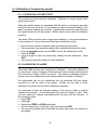
6.9.2 INITIALIZATION
Initialization restores the factory default settings to the monitor. The whole
controller can be initialized or just the calibrations. This will clear any random
settings that may be in the monitor.
To initialize the calibrations:
•
•
•
From the Main Menu, press ”6” SYSTEM SETUP.
Press ”2” INITIALIZATION.
Press ”1” CALIBRATIONS. The WHICH INPUT DEVICE screen will appear.
WHICH INPUT DEVICE?
=====================
1 pH/ORP
2 COND
3 TEMP
•
Use the arrow keys to highlight the input to initialize and press the ENT key.
WARNING:
THIS OPTION REQUIRES
RE-CALIBRATION AND REPROGRAMMING!
PROCEED?
1 YES
2 NO
•
Use the arrow keys to highlight “1” YES and press the ENT key.
To initialize the whole controller:
•
•
•
From the Main Menu, press ”6” SYSTEM SETUP.
Press ”2” INITIALIZATION.
Press “2” WHOLE CONTROLLER.
WARNING:
THIS OPTION REQUIRES
RE-CALIBRATION AND REPROGRAMMING!
PROCEED?
1 YES
2 NO
•
Use the arrow keys to highlight “1” YES and press the ENT key.
NOTE: Initializing the WHOLE CONTROLLER deletes all user settings and
will require reprogramming the Whole Controller.
52
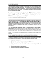
6.9.3 SECURITY (CHANGE THE PASSWORDS)
The security password can be changed from the factory default settings to any
four-digit value of your choice.
To change the security passwords:
•
•
From the Main Menu, press ”6” SYSTEM SETUP.
Press ”3” SECURITY.
CHANGE PASSWORD
=====================
1 OPERATOR
2 TECHNICIAN
•
Press “1” OPERATOR to change the operator password or Press “2”
TECHNICIAN to change the technician password.
TECHNICIAN
PASSWORDS ARE 4 KEYS
ENTER A NEW PASSWORD
OLD PASSWORD= ****
NEW PASSWORD= ****
VERIFY
= ****
•
•
•
Use the keypad to enter the old password. If the password has not been
changed before, the old password for OPERATOR is 1111 and the password
for TECHNICIAN is 2222.
Use the keypad to enter the new password.
Use the keypad to enter the new password a second time for verification
If you lose your password, contact Lakewood Instruments for assistance.
6.9.4 SOFTWARE VERSIONS
Sometimes it is necessary to verify the software versions of the controller for
troubleshooting purposes. To obtain the software versions:
•
•
•
From the Main Menu, press ”6” SYSTEM SETUP.
Press ”4” SOFTWARE VERSIONS.
The software versions will be displayed. Use the arrow keys to view all
software versions. To exit this screen, press “CLR”.
53
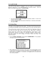
6.9.5 TIMERS
The model 2450e includes timers for machine run time, lubrication interval, check
CIP, check filters, check membranes, and check sensor. The machine run time
timer keeps track of actual machine run time and counts up. All the other timers
are based on machine run time and count down from a user programmed machine
run time and will trigger timer alarms notifying the user that an action needs to be
performed.
The timer setup screens allow the user to reset the timers to zero and, in the case
of all timers except the machine run time, allow the user to set the number of
hours until the timer alarm occurs.
To access the timers:
•
•
From the Main Menu, press ”6” SYSTEM SETUP.
Press ”5” TIMERS.
TIMERS
=====================
1 MACHINE RUN TIME
2 LUBRICATION
3 CHECK CIP
4 CHECK FILTERS
5 CHECK MEMBRANES
6 CHECK SENSOR
•
Use the arrow keys to highlight the timer and press the ENT key.
LUBRICATION INTERVAL
=====================
1 VIEW/RESET TIMER
2 SET TIMER
To view or reset the timer press “1” VIEW/RESET TIMER.
TIME IN HOURS:MINS
TILL NEXT ALARM:
0:00
RESET TIMER?
1 YES
2 NO
•
Press “1” YES to reset the alarm timer to the user programmed time.
54
To set the timer press “2” SET TIMER.
THE CONTROLLER WILL
ACTIVATE A TIMER
ALARM AFTER THIS
NUMBER OF HOURS:
500:00
PRO:”+/-“
•
ENT:ACCEPT
Use the keypad to set the timer and press the ENT key.
6.9.6 Diagnostics
The diagnostics screen is used for troubleshooting purposes. Contact Lakewood
Instruments for assistance.
6.9.7 Communications
The model 2450e has an option for remote communications, the –RS2L option. If
this option is installed, the communications option is configured from this screen.
This screen is used to set up the com port, initialize the modem, and set the
remote password.
To set up the communications option:
•
•
From the Main Menu, press ”6” SYSTEM SETUP.
Press ”7” COMMUNICATIONS.
COMMUNICATIONS
=======================
1 COM PORT SETUP
2 INITIALIZE MODEM
3 REMOTE PASSWORD
55
6.9.7.1 Com Port Setup
Com port setup is used to set up the com port for use with a modem or direct
connect.
•
To set up the com port press “1” COM PORT SETUP
COM PORT PARAMETERS
=======================
BAUD RATE: 19200
DATA BITS: 8
STOP BITS: 1
PARITY
: NONE
<UP><DOWN> ENT: ACCEPT
•
•
Use the arrow keys to change the baud rate. If using the direct connect
method of communicating, ensure that the baud rate at the controller and the
baud rate in the LRWS software match.
The standard values for the DATA BITS is 8, STOP BITS is 1, and PARITY is
NONE. Normally these will not need to be changed.
6.9.7.2 Initialize Modem
Before a modem can be used by the controller it must be initialized.
initialization screen gives four choices of modems.
The
To initialize the modem:
•
From the Communications menu, press “2” INITIALIZE MODEM
INITIALIZE MODEM
=======================
1 HAYES ACCURA
2 U.S. ROBOTICS
3 ZOOM
4 OTHER MODEM
•
•
Select your modem from the list. If your modem is not listed and you select
OTHER MODEM use the keypad to enter the initialization string for your
modem.
If the modem fails to initialize, check the 25-pin connector, the phone cable, the
modem, and the –RS2L option card.
56
6.9.7.3 Remote Password
Remote communications to the Lakewood Instruments 2000 series controllers is
protected with an 8-digit password. The remote password is required to make
changes to the model 2450e controller using the communications option card.
The remote password screen in the communications menu is used to change the
remote password. The remote password can only be changed at the
controller.
To change the remote password:
•
•
•
From the communications menu, press “3” REMOTE PASSWORD.
Use the keypad to enter the old password. Enter the new password. Repeat
the new password again for verification. NOTE: The default password is
12345678.
Set the remote password in the LRWS program to match the new password for
this controller.
6.10 SETTING THE CLOCK
The clock uses the 24 hour or military time. 06:00:00 is 6 a.m. 18:00:00 is 6 p.m. To
set the clock:
•
From the Main Menu press ”8” CLOCK. The following screen will appear:
MON
15 AUG ‘11
11:23:13
PRO: CHANGE; CLR: EXIT
•
•
•
•
•
•
•
•
•
Press ”PRO” to change the clock settings.
Use the up and down arrow keys to change the day of the week. Press ”ENT”.
Use the number keys to change the date. Press ”ENT”.
Use the arrow keys to change the month. Press ”ENT”.
Use the number keys to change the year. Press ”ENT”.
Use the number keys to change the hour. Press ”ENT”.
Use the number keys to change the minutes. Press ”ENT”.
Use the number keys to change the seconds. Press ”ENT”.
Press ”CLR” to exit this screen.
You must press “ENT” all the way through this menu for the settings to take affect.
57
6.11 Changing the Security Levels
The model 2450e has three security levels: Technician, which allows full access
to all screens; Operator, which allows access to the operations screens, manual
relay screen, and calibration screens; and View-Only, which allows access to the
operations screens, and manual relay screen.
The security level can be change to prevent any unwanted tampering of the
controller. To change the security level from Technician to Operator or ViewOnly:
•
From the Main Menu, press “0”. (Note that “0” does not appear on the menu
screen.)
SET SECURITY LEVEL
====================
1 VIEW-ONLY
2 OPERATOR
•
Select VIEW-ONLY for the most restrictive level or OPERATOR for a less
restrictive level of access.
CHANGE LEVEL TO OPERATOR
?
WARNING:YOU SHOULD KNOW
THE PASSWORD.
1 YES
2 NO
•
Select YES to change the security level to a more restrictive level.
controller menu now functions at the new security level.
The
To return to the Technician security level:
•
From the Operation screen, use the keypad to enter the 4-digit numeric
password for the Technician security level:
TECHNICIAN
PRESS ANY KEY
Note: The default Technician password is 2222 and the Operator password
is 1111. Passwords can be changed in the SYSTEM SETUP menu.
58
7.0 Maintenance
Periodic maintenance is required to ensure trouble free operation of the model
2450e controller. The following sections cover the required maintenance.
7.1 Sensor Maintenance
Routine maintenance is necessary in order to maximize the efficiency and
accuracy of your sensor.
7.1.1 Conductivity Sensor
Clean the electrode end of the Conductivity sensor at least once per month.
Cleaning of the Conductivity sensor may need to be performed more frequently if it
is in a high fouling environment.
• Remove power from the controller and shut off the sample flow.
• Remove the sensor from its plumbing.
• Clean the electrodes with a wire brush. A soft steel brush is preferable to a
brass brush. Do not use cloth to clean the electrodes. Cloth has oils that will
foul the sensor.
• If there is oil on the sensor glass, use isopropyl alcohol to clean the electrode.
• It is recommended that you use a 10% Muriatic or HCL acid to clean the
sensor if necessary.
• Wash the sensor off with tap water.
• Install the sensor in its plumbing.
• Restore sample flow and check for leaks.
• Restore power to the controller.
• Perform a calibration of the Conductivity.
59
7.1.2 pH/ORP Sensor
Clean the electrode end of the pH or sensor at least once per month. Cleaning of
the pH or ORP sensor may need to be performed more frequently if it is in a high
fouling environment.
• Remove power from the controller and shut off the sample flow.
• Remove the sensor from its plumbing.
• Be careful not to touch the glass electrode. Do not use cloth to clean the
electrode. Cloth has oils that will foul the sensor.
• If there is oil on the sensor glass, use isopropyl alcohol to clean the electrode.
• It is recommended that you use a 10% Muriatic or HCL acid to clean the
sensor.
• Wash the sensor off with tap water.
• Install the sensor in its plumbing.
• Restore sample flow and check for leaks.
• Restore power to the controller.
• Allow the reading to stabilize for approximately 30 minutes.
• Perform a calibration of the pH or ORP.
7.2 Replacing the Fuse
The Model 2450e contains a 10A, 250V fuse. The fuse holder is located on the
bottom of the enclosure.
It is accessible from the outside of the box.
Replacement fuses must be a fast blow type. If the fuse is blown, the display will
be blank and the four power supply lights inside the controller enclosure will be
dark when the unit is connected to power. Refer to the troubleshooting section of
this manual for more information about blank displays.
60
8.0 TROUBLESHOOTING
PROBLEM
Conductivity Calibration
Error message: “SENSOR
READING HIGHER THAN
EXPECTED.”
Conductivity Calibration
Error message: “SENSOR
READING LOWER THAN
EXPECTED.”
WHAT THIS MEANS
CORRECTIVE ACTION
The Monitor is being told the
conductivity is 50% more than
it thinks it is by default.
1.
Is the Monitor being calibrated to
TDS when configured for
conductivity?
2.
Verify that the sensor tip has no
accumulated solids and has not
bridged to piping (creating a short).
3.
Clean tip.
The Monitor is being told the
conductivity is 50% less than
it thinks it is by default.
1. Is the sensor fouled?
2. Are all valves open?
3. Clean or replace sensor.
Conductivity drifts or
changes after calibration.
Water meters not
accumulating.
Calibration may have been
done before the reading
stabilized.
1. When calibrating, wait at least
15 seconds to 1½ minutes for
reading to stabilize.
The sample line may contain
electrical noise.
2. To reduce electrical noise, use
grounded metal fittings on the
inlet and outlet of the Monitor
plumbing.
Check the manufacturer’s
user manual for that particular
water meter.
1. There may be a wiring problem.
2. The K factor is improperly
configured.
3. If using a turbine meter, verify
that turbine is actually spinning.
“NODE NOT RESPONDING”
error message.
This message occurs when
one circuit board in the
Monitor cannot communicate
with another board.
1. Check that all boards are
mounted correctly and that all
connectors are fully mated.
2. The Monitor may not have the
option board that is trying to be
accessed.
3. The board that is trying to be
accessed may not be working.
61
P PROBLEM
Display is blank.
pH reading is off by more
than 1 pH unit.
WHAT THIS MEANS
CORRECTIVE ACTION
Open the front panel. Look at
the yellow LED’s on the rear
power board. Are they on?
1. If LED’s are on, check ribbon
cable. Is it properly seated?
Probe calibrated using span,
or the pH probe is bad.
1. Re-initialize calibration.
2. If LED’s are not on, does the
unit have power?
2. Recalibrate pH using zero only.
3. Replace pH sensor.
mV reading is off by more
than 100 mV.
ORP Probe might be
inaccurate.
1. Re-initialize calibration.
2. Recalibrate zero, span, or both.
3. Replace ORP sensor.
Relays don’t turn ON/OFF
during normal operation.
Relays may be affected by
other software variables.
1. Is the relay manually turned on
or off?
2. Is the CIP input activated?
3. You must have permeate or
concentrate flow for a relay
configured as setpoint to
function.
Chemical pump will not feed
chemical.
Pumping may be affected by
other software variables.
1. Is the pump manually turned on
or off?
2. Is the CIP input activated?
3. You must have permeate or
concentrate flow for a relay
configured as setpoint to
function and trigger pump
operation.
Chemical pump feed reverse
of what you expected.
{ALARM FLASHING}
“RLY1:TIME EXCEEDED”
“RLY2:TIME EXCEEDED”
“RLY3:TIME EXCEEDED”
“RLY4:TIME EXCEEDED”
Relay setpoint not properly
configured.
Determine whether you need the
relay configured for direct or
reverse setpoint feed.
The relay was not able to
control the pH/ORP setpoint
within the programmed overfeed time. The relay is locked
out until the alarm goes away.
1. Reprogram the over-feed time
via “RELAYS/SETPOINT”.
2. Determine why the chemical
feed is failing to control the
solution pH/ORP.
3. To reset the alarm, temporarily
stop permeate and concentrate
flow.
62
P PROBLEM
{ALARM FLASHING}
“pH :HIGH ALARM” or
“ORP :HIGH ALARM”
{ALARM FLASHING}
“pH :LOW ALARM” or
“ORP :LOW ALARM”
{ALARM FLASHING}
“COND:HIGH ALARM”
{ALARM FLASHING}
“TEMP:HIGH ALARM”
{ALARM FLASHING}
“PERM:HIGH ALARM”
{ALARM FLASHING}
“PERM:LOW ALARM”
{ALARM FLASHING}
“FEED:HIGH ALARM”
{ALARM FLASHING}
“FEED:LOW ALARM”
{ALARM FLASHING}
“%REC:HIGH ALARM”
{ALARM FLASHING}
“LUBRICATION INTERVAL”
{ALARM FLASHING}
“CHECK CIP”
{ALARM FLASHING}
“CHECK FILTERS”
WHAT THIS MEANS
CORRECTIVE ACTION
The pH/ORP has exceeded
the user-programmed high
alarm value.
See “ALARMS” in Main Menu.
The pH/ORP has exceeded
the user-programmed low
alarm value.
See “ALARMS” in Main Menu.
The conductivity has
exceeded the userprogrammed high alarm
value.
See “ALARMS” in Main Menu.
The temperature has
exceeded the userprogrammed high alarm
value.
See “ALARMS” in Main Menu.
The permeate flow rate has
exceeded the userprogrammed high alarm
value.
See “ALARMS” in Main Menu.
The permeate flow rate has
exceeded the userprogrammed low alarm value.
See “ALARMS” in Main Menu.
The feed water flow rate has
exceeded the userprogrammed high alarm
value.
See “ALARMS” in Main Menu.
The feed water flow rate has
exceeded the userprogrammed low alarm value.
See “ALARMS” in Main Menu.
The percent recovery has
exceeded the userprogrammed high alarm
value.
See “ALARMS” in Main Menu.
The lubrication interval timer
has expired.
See “SYSTEM SETUP/TIMERS” to
reset the timer.
The Check CIP interval timer
has expired.
See “SYSTEM SETUP/TIMERS” to
reset the timer.
The Check Filters interval
timer has expired.
See “SYSTEM SETUP/TIMERS” to
reset the timer.
63
P PROBLEM
{ALARM FLASHING}
“CHECK MEMBRANES”
{ALARM FLASHING}
“CHECK SENSOR”
{ALARM FLASHING}
“COND:FOULED SENSOR”
{ALARM FLASHING}
“SHORTED TC”
{ALARM FLASHING}
“OPENED TC”
{ALARM FLASHING}
“pH :HI REF IMPEDANCE“
or
“ORP :HI REF IMPEDANCE“
{ALARM FLASHING}
“pH :BROKEN GLASS”
WHAT THIS MEANS
CORRECTIVE ACTION
The Check Membranes interval timer
has expired.
See “SYSTEM SETUP/TIMERS” to
reset the timer.
The Check Sensor interval timer
has expired.
See “SYSTEM SETUP/TIMERS” to
reset the timer.
The conductivity sensor has
become fouled.
Check cable, sensor, and wiring.
The temperature compensation
input is shorted.
Check cable, sensor, and wiring.
The temperature compensation
input is opened.
Check cable, sensor, and wiring.
1.
1.
Replace pH/ORP Sensor.
2.
Sensor must be grounded.
1.
Check glass bulb on the pH sensor.
2.
Replace sensor if necessary.
A high reference impedance
exists in the pH/ORP
sensor.
2.
A wire may be broken in the
sensor.
3.
KCl solution in the sensor
may be leaking (pH only).
The pH sensor glass may be
broken.
{ALARM FLASHING}
“pH :HIGH REF VOLTAGE“
or
“ORP :HIGH REF VOLTAGE“
High reference voltage exists in
the pH/ORP sensor.
Check sensor wiring.
{ALARM FLASHING}
“pH :LOW REF VOLTAGE”
or
“ORP :LOW REF VOLTAGE”
Low reference voltage exists in
the pH/ORP sensor.
Check sensor wiring.
{ALARM FLASHING}
“CIP SWITCH CLOSED”
1.
The Clean-in-Place switch
input condition has become
asserted.
None, unless the input is wired
incorrectly.
2.
Relays are locked out.
64
9.0 FACTORY SERVICE
Technical Support for Lakewood Instruments can be reached by calling (800) 2280839 or faxing (414) 355-3508, Monday through Friday, 7:30 a.m. – 5.00 p.m.
CST.
NOTE: IF YOU CALL FOR TROUBLESHOOTING HELP, PLEASE HAVE THE
MODEL NUMBER, SERIAL NUMBER, AND ANY OPTIONS PERTAINING TO
YOUR UNIT AVAILABLE FOR REFERENCE.
Mail and returns should be sent to:
Lakewood Instruments
7838 North Faulkner Road
Milwaukee, WI 53224 USA
When any merchandise is to be returned to the factory, please call and obtain a
Return Goods Authorization (RGA) number and have the following information
available:
•
•
•
•
•
Customer’s name, address, telephone and fax numbers (shipping and billing).
A hard copy purchase order number for cases where repairs or parts are
required that are not under warranty.
A contact person’s name and telephone number to call if the equipment is
beyond repair or to discuss any other warranty matter.
Equipment model and serial numbers.
Reason for return, e.g., repair, warranty, incorrect part, etc.
We will then fax to your attention an RGA form that must accompany the returned
item.
NOTE: THE RGA NUMBER MUST BE CLEARLY WRITTEN ON THE OUTSIDE
OF THE PACKAGE(S) BEING RETURNED.
ANY ITEMS SENT BACK TO THE FACTORY
WITHOUT AN RGA NUMBER WILL BE REFUSED
AND RETURNED TO SENDER
65
10.0 DRAWINGS
For more information call toll free in the USA (800) 228-0839
Manufactured in the USA
Lakewood Instruments
7838 North Faulkner Road, Milwaukee, WI 53224 USA
Phone (800) 228-0839 • Fax (414) 355-3508
http://www.lakewoodinstruments.com