1
PROMDISK IV Disk Emulator User's Manual
For MCSI PART NO. 66700901
Solid State Disk Emulator Board
For Industrial/Embedded System Applications
MICRO COMPUTER SPECIALISTS, INC.
"The Embedded PC Specialists"
2598 Fortune Way
Vista, CA 92083
U.S.A.
Voice (760) 598-2177 - Fax (760) 598-2450
Technical Support BBS (760) 598-2179
Sixth Edition (January 1997)
Revision 2.3
Changes are made periodically to the information contained herein; these changes will be incorporated
into new editions of this document.
Requests for copies of this publication or the product(s) which it describes should be made to MCSI.
While every effort has been made to insure that this document and its accompanying
product(s) are free from defects, MCSI, its distributors, representatives, and employees shall
not be responsible for any loss of profit or any other commercial damage including, but not
limited to, special, incidental, consequential, or other damages occasioned by the use of this
product(s).
In the event of defect the buyer's sole recourse is to receive a refund or replacement unit at
MCSI's discretion if notified within the time period covered by the product warranty.
1995 MCSI Micro Computer Specialists, Inc. All Rights Reserved.
PROMDISK is a registered trademark of MCSI.
IBM is a registered trademark of International Business Machines Corporation.
PC/XT & PC/AT are registered trademarks of International Business Machines Corporation
MS-DOS is a registered trademark of Microsoft Corporation.
INTEL & FLASH are registered trademarks of Intel Corporation.
All other trademarks are the properties of their respective holders.
PREFACE
This manual provides information about the MCSI PROMDISK IV Disk Emulator Board and related
software utility programs. This information is intended for users who must implement IBM PC/AT
compatible computer solutions to a wide variety of applications which cannot be satisfied using
conventional desktop computers. This manual assumes that the reader has a good understanding of
MS-DOS and the standard IBM PC/AT compatible architecture. For more information on the IBM PC
compatible hardware and software architecture, refer to any of the many books available on the subject.
A few suggestions are listed below:
•Advanced MS-DOS Programming, Microsoft Press
•Programmers Guide to the IBM PC, Microsoft Press
•Undocumented DOS, Addison Wesley
INVENTORY CHECKLIST
The complete PROMDISK IV Disk Emulator package consists of the following:
PROMDISK IV Disk Emulator Board
This Manual
One Diskette containing:
PROMDISK Software Utilities
If any of the above is missing or appears to be damaged, inform MCSI immediately. Note that for
quantity shipments, only one copy of this manual and one diskette is included, unless otherwise
requested.
Table of Contents
Section 1 - Introduction _________________________________________________________________1
1.1 Features....................................................................................................................................................................... 1
Section 2 - General Description ___________________________________________________________2
2.1 PROMDISK Memory ............................................................................................................................................... 2
2.2 Memory Write Protect ............................................................................................................................................. 2
2.3 SRAM Battery Back-Up .......................................................................................................................................... 3
2.4 PROMDISK Power Requirements ....................................................................................................................... 3
Section 3 - PROMDISK Hardware Setup____________________________________________________4
3.1 Setting the ROM-SCAN Address......................................................................................................................... 4
3.2 Configuring the Drives........................................................................................................................................... 4
3.3 PROMDISK Memory Configuration Jumpers.................................................................................................. 5
3.4 PROMDISK Power Selection................................................................................................................................. 5
3.5 Installing the Memory Chips................................................................................................................................ 6
Section 4 - Using PROMDISK ____________________________________________________________8
4.1 Using SRAMs with PROMDISK.......................................................................................................................... 8
4.1.1 Formatting SRAMs in the Floppy Disk Mode........................................................................................ 8
4.1.2 Formatting SRAMs in the Fixed Disk Mode........................................................................................... 9
4.1.3 Software Write Protect for SRAM Drives.................................................................................................. 9
4.2 Using EPROMs with PROMDISK....................................................................................................................... 10
4.2.1 Creating a PROMDISK List File or Work Disk....................................................................................... 10
4.2.2 Sizing the PROMDISK .................................................................................................................................. 12
4.2.3 Programming the FLASH EPROMs......................................................................................................... 12
4.2.4 Programming 5V-Only FLASH EPROMs............................................................................................... 13
4.2.5 Programming Standard EPROMs ............................................................................................................. 13
4.2.6 Programming the EPROM Drive A ........................................................................................................... 14
4.3 Emulating Floppy Drives C through Z.............................................................................................................. 14
4.4 Dynamic Drive Assignment.................................................................................................................................. 15
4.5 PROMDISK Custom Features............................................................................................................................... 16
Section 5 - FlashCom ___________________________________________________________________17
5.1 How Does FlashCom Operate?............................................................................................................................. 17
5.2 FlashCom Components.......................................................................................................................................... 17
5.2.1 UPLOAD .................................................................................................................................................................. 18
5.2.2 Upload Programming and Verification Options.......................................................................................... 19
5.3 General Purpose RS-232 File Transfer Programs ............................................................................................ 19
5.3.1 Using PUTFILE....................................................................................................................................................... 19
5.3.2 Using GETFILE....................................................................................................................................................... 19
5.4 Other Uses For FlashCom....................................................................................................................................... 20
Section 6 - PROMDISK Installation ________________________________________________________21
6.1 Setting Up Your System for PROMDISK ........................................................................................................... 21
6.2 Installing PROMDISK in Your System .............................................................................................................. 21
Appendix A - Specifications _____________________________________________________________22
Appendix B - PROMDISK IV Jumper Locations ______________________________________________23
Appendix C - ROMSCAN Address Settings _________________________________________________24
Appendix D - PROMDISK Drive Configurations_____________________________________________ 25
Appendix E - PROMDISK Memory Selection Jumpers_________________________________________ 26
SECTION 1 - INTRODUCTION
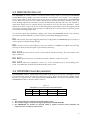
With the advent of IBM PC compatible boards for creating dedicated systems, there exists a need to
provide a method by which a DOS (MS-DOS, PC-DOS, ROM-DOS, QNX, etc.) application program can
become part of a target system without requiring a disk. Many times a physical disk will not operate in
the environment in which the target machine is to be placed. Also, the added cost of a disk controller,
disk, and other associated equipment increase the cost of the target machine. Development time can be
reduced by creating an environment in which programs can be developed and tested on standard PCs
utilizing your DOS system utilities. What happens if a disk cannot be part of the target system? DOS
will not operate because the operating environment is changed between the development system and the
target system.
MCSI has a total solution for this problem -- the MCSI PROMDISK IV Disk Emulator Board! PROMDISK
can emulate up to three Read-Only or Read/Write floppy or fixed disk drives with capacities ranging
from 32K to 4M-byte. This means that a program developed utilizing DOS on any PC Compatible will
run without a disk in a target application system! PROMDISK IV can be configured as one 4M-byte drive,
two 2M-byte drives, or one 2M-byte drive, one 1.5M-byte drive, and one 512K-byte drive. In addition, you
can also use PROMDISK with other physical drives in the system. Therefore, DOS can boot from a
PROMDISK drive A and read the application code from a physical disk in the system, creating a flexible
development environment. When the code on the B disk is complete, transfer it to PROMDISK, remove
the physical disk, and the target system will operate with no physical disk in the system!
1.1 FEATURES
A complete list of features is listed below:
•
•
•
•
•
•
•
•
•
•
•
•
•
•
IBM PC/XT/AT Compatible
Capacity up to 4M-byte
Emulates Both Floppy and Fixed Disk Drives
Emulates up to Three Drives Simultaneously
Emulates Both Read/Write and Read-Only Drives
Supports Eight 28/32-pin Standard Byte-wide Memories
Occupies Only 32K of Memory Address Space
Includes On-board Programmer for FLASH EPROMs
On-Board Battery for Nonvolatile Operation
Supports both 12V and 5V Only FLASH EPROMs
Passive Backplane Architecture
Ideally Suited for DISKLESS Applications
Low Power CMOS Design
Standard Half-Size "XT" Plug-in Board
1
SECTION 2 - GENERAL DESCRIPTION
The PROMDISK Disk Emulator is a unique memory board designed to emulate DOS compatible disk
drives for use in IBM PC/XT/AT compatible computers as a replacement for floppy or hard disk drives.
It occupies only 32K bytes of address space that is DIP switch selectable from address C0000H through
F0000H on 8000H boundaries.
PROMDISK will support up to eight JEDEC standard memory devices ranging in density from 32Kx8 to
512Kx8, for a total capacity of 4M-byte. It allows the use of SRAMs or NVRAMs to fully emulate a
Read/Write floppy and fixed disk drives.
DOS files are converted into EPROM images using the PROMDISK PDCREATE.EXE utility program.
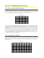
2.1 PROMDISK MEMORY
The PROMDISK applications memory is made up of eight JEDEC standard byte-wide memory sockets
which may be configured to accept EPROMs, FLASH EPROMs, SRAMs, and NVRAMs. The chip
sockets are arranged into three logical drives in accordance with the Table 2.1 below:
Table 2.1
PROMDISK IV
CHIP SOCKET/DRIVE CONFIGURATION
DRIVE
REF
JUMPER
CHIPS
SIZE*
1
2
3
U1-U4
U5-U7
U8
E5
E6
E7
4
3
1
2M
1.5M
512K
* maximum size
The three drives are logically assigned by the control ROM for booting purposes and may be reassigned
once the operating system is loaded using the PDASSIGN.COM software utility. The memory
configuration jumpers select the size and type of memory chips used for each drive. The type of chips
within a drive may not be mixed. For the proper selections refer to Table 3.3.
2.2 MEMORY WRITE PROTECT
The PROMDISK IV Disk Emulator board incorporates a software means of write protection when
emulating a Read/Write disk using SRAMs. The programmable write protect bit may be set or reset using
the PROMDISK PDPRO.COM utility program. In addition the PROMDISK IV board also incorporates
hardware write protection for both FLASH EPROMs and SRAMs. DIP switch SW1 position nine is the
hardware write protect bit. The FLASH EPROMs and SRAMs are write protected by setting DIP switch
SW1 position nine to the "OFF" position. Setting position nine to the "ON" position enables the FLASH
EPROM and SRAM write function.
2
2.3 SRAM BATTERY BACK-UP
The PROMDISK IV board contains an on-board Lithium battery used for powering the PROMDISK
CMOS SRAMs during standby operation in the absence of the normal +5 volt supply. A set of jumpers
E1-E3 are provided to select either normal system power or battery backed power for the PROMDISK
sockets. Refer to Section 3.4 for more details. During normal operation, the battery should last five years
before needing replacement. The battery must be unsoldered from the PCB and a new one installed. A
replacement battery may be ordered directly from MCSI or from any electronics distributor. Order
Tadiran P/N 5101A. To prevent the loss of data during battery replacement, remove the jumper from E4
and connect an external battery between E4 pin 1(-) and E4 pin 2(+). After the battery is replaced, be sure
to reinstall the shorting jumper at E4.
Care must be taken when handling, shipping, and storing the PROMDISK board. The following
precautions should be adhered to in order to prevent accidentally damaging the battery:
DO take extreme care when configuring the memory configuration and PROMDISK power jumpers in
order to prevent accidental battery damage.
DO store the board in a nonconductive, static free container, or INSIDE the original Anti-Static Bag.
This bag has been specially designed to prevent battery discharge.
DO NOT allow the board to come in contact with the outside of the bag. The outer surface of the
bag is conductive.
DO NOT place the board on a metal bench or other conductive surface at any time.
DO NOT connect any equipment, circuits, etc., to the on-board battery as serious damage may
result. Any additional current drain will dramatically reduce its life.
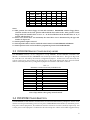
2.4 PROMDISK POWER REQUIREMENTS
The PROMDISK board is implemented using CMOS technology for low power consumption and is
powered from the +5VDC I/O expansion bus power supply. The board also uses the +12VDC supply
from the I/O expansion bus when programming FLASH EPROMs. The power requirements for the
PROMDISK IV board are shown in Table 2.4 below:
Table 2.4
PROMDISK IV BOARD POWER REQUIREMENTS
Voltage
+5VDC
+12VDC
Tolerance
10%
10%
Operating
80 ma.
0 ma.
Programming
80 ma.
40 ma.
Standby
50 ma.
0 ma.
Notes:
1. The values in the above table do not include memory chips.
2. The +12VDC supply is used only during programming of FLASH EPROMs.
3. The PROMDISK IV includes an optional 5VDC to 12VDC converter which eliminates the
requirement for +12VDC from the I/O bus.
3
SECTION 3 - PROMDISK HARDWARE SETUP
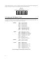
3.1 SETTING THE ROM-SCAN ADDRESS
The PROMDISK Disk Emulator board is controlled by an on-board control program which must be
located in the ROM-SCAN address space of an IBM PC/XT/AT compatible computer. The control
firmware is contained in a 64K byte ROM located at U9. The absolute address is selected by DIP switch
SW1. The address selections and DIP switch settings are shown in Table 3.1 below:
Table 3.1
ROM-SCAN ADDRESS SW1
ADDRESS
SW1-1
SW1-2
SW1-3
C0000H
ON
ON
ON
C8000H
ON
ON
OFF
D0000H
ON
OFF
ON
D8000H
ON
OFF
OFF
E0000H
OFF
ON
ON
E8000H
OFF
ON
OFF
F0000H
OFF
OFF
ON
Note: Shaded area indicates default setting
Care must be taken when using addresses C0000H and F0000H. Some of the earlier BIOSs will scan
these addresses, allowing PROMDISK to operate properly. However, most of the new BIOSs reserve
these two addresses for extended video adapters and BIOS extensions, and therefore may cause
PROMDISK to operate incorrectly. The only other precaution one must be aware of when selecting the
ROM-Scan address is that no other device occupies the selected address space. Be aware that some
systems have shadow memory and/or extended memory addressed at D0000H or E0000H. In light of
this, be sure to disable these functions if they conflict with the PROMDISK address you have chosen, or
select another starting address. Also when using EMM386.EXE or other memory drivers be sure to
exclude the address block used by PROMDISK.
3.2 CONFIGURING THE DRIVES
The on-board control ROM contains sixteen of the most commonly used disk drive configurations
(others are available upon request). The configuration DIP switch SW1 positions 4-7 are used to select
the disk drive configurations. Table 3.2 below lists the disk drive configurations and the applicable SW1
switch settings.
Table 3.2
PROMDISK IV DRIVE CONFIGURATION SWITCH SW1
No.
0
1
2
3
4
5
6
7
8
4
DRIVE1
U1-U4
DRIVE2
U5-U7
DRIVE3
U8
SW1-4
SW1-5
SW1-6
SW1-7
A (4M)
B (4M)
A (2M)
B (2M)
A (2M)
B (2M)
B (2M)
C (2M)
C(4M)
A
B
B (2M)
C (2M)
B (1.5M)
C (1.5M)
A (1.5M)
B (1.5M)
C
A
B
B
C
C (512K)
D (512K)
C (512K)
A (512K)
C
ON
ON
ON
ON
ON
ON
ON
ON
OFF
ON
ON
ON
ON
OFF
OFF
OFF
OFF
ON
ON
ON
OFF
OFF
ON
ON
OFF
OFF
ON
ON
OFF
ON
OFF
ON
OFF
ON
OFF
ON
9
No.
D (4M)
DRIVE1
U1-U4
D
DRIVE2
U5-U7
D
DRIVE3
U8
OFF
SW1-4
ON
SW1-5
ON
SW1-6
OFF
SW1-7
10
11
12
13
14
15
C (2M)
C(3.5M)
B (3.5M)
C (2M)
C (3.5M)
D (3.5M)
B (2M)
C
B
D (2M)
C
D
B
B (512K)
C (512K)
D
D (512K)
C (512K)
OFF
OFF
OFF
OFF
OFF
OFF
ON
ON
OFF
OFF
OFF
OFF
OFF
OFF
ON
ON
OFF
OFF
ON
OFF
ON
OFF
ON
OFF
Notes:
1.0 SW1 position four selects floppy or fixed disk emulation. PROMDISK emulates floppy drives
when the switch is in the "ON" position and fixed disk drives when in the "OFF" position. In the
floppy mode the bootable drive is set to "A". In the fixed disk mode the bootable drive is "A", if
present, and then drive "C".
2.0 Drive sizes shown above are maximums; the actual drive size is determined by the type and
number of chips used.
3.0 Switch position eight is not used.
4.0 Switch position nine is used to enable the write feature for FLASH EPROMs and SRAMs.
5.0 Switch position ten is used to enable the programming feature for FLASH EPROMs.
3.3 PROMDISK MEMORY CONFIGURATION JUMPERS
The PROMDISK memory can be configured to accept EPROMs, FLASH EPROMs, NVRAMs, and
SRAMs. As mentioned earlier, PROMDISK can emulate up to three disk drives. The type of chips used
for each drive are selected by the memory configuration jumpers. Sockets U1-U4 are selected by E5,
sockets U5-U7 by E6, and socket U8 by E7. The type of chips used within each drive cannot be mixed
and are selected by the memory configuration jumpers in accordance with Table 3.3 below:
Table 3.3
MEMORY CONFIGURATION JUMPERS E5-E7
TYPE
SIZE
JUMPER E5-E7
EPROM
EPROM
EPROM
EPROM
EPROM
SRAM or NVRAM
SRAM or NVRAM
SRAM or NVRAM
FLASH EPROM
FLASH EPROM
28/29F040
32Kx8
64Kx8
128Kx8
256Kx8
512Kx8
32Kx8
128Kx8
512Kx8
128Kx8
256Kx8
512Kx8
5-6 & 15-16
1-2 & 5-6 & 15-16
1-2 & 5-6 & 13-14 & 21-22
1-2 & 5-6 & 13-14 & 21-22
1-2 & 5-6 & 13-14 & 21-22 & 23-24
3-4 & 7-8 & 15-16
3-4 & 7-8 & 11-12 &15-16
3-4 & 7-8 & 11-12 & 13-14 & 17-18
1-2 & 5-6 & 9-10 & 13-14 & 19-20
1-2 & 5-6 & 9-10 & 13-14 & 19-20
1-2 & 5-6 & 9-10 & 13-14 & 17-18
Note: Chips within a drive group cannot be mixed.
3.4 PROMDISK POWER SELECTION
The PROMDISK IV Disk Emulator board features an on-board Lithium battery and power control circuit
which is used to provide battery power to low power CMOS SRAMs in the absence of normal DC power.
The power control jumpers E1, E3, and E2 are used for sockets U1-U4, U5-U7, and U8, respectively. Pin
3 of the power control jumpers is connected to the on-board power control circuit which supplies battery
5
current when the normal +5 volts is not present. Extreme care must be taken when configuring these
jumpers. The setup for the power control jumpers is shown in Table 3.4 below:
Table 3.4
PROMDISK IV
POWER CONTROL JUMPERS E1, E3, & E2
Power
Mode
E1
U1-U4
E3
U5-U7
E2
U8
Normal
Battery
1-2
2-3
1-2
2-3
1-2
2-3
3.5 INSTALLING THE MEMORY CHIPS
The PROMDISK Disk Emulator board supports the popular JEDEC standard byte-wide memory devices.
For proper operation the devices should have a maximum access time of less than 150 nanoseconds. The
following is a list of some of the more common generic chip types:
EPROM:
32Kx8
64Kx8
128Kx8
256Kx8
512Kx8
32Kx8
64Kx8
128Kx8
256Kx8
D27C256-150 Intel
D27C512-150 Intel
D27C010-150 Intel
D27C020-150 Intel
D27C040-150 Intel
AT27C256R-15DC Atmel
AT27C512R-15DC Atmel
AT27C010R-15DC Atmel
AM27C020-150DC AMD
SRAM:
32Kx8
128Kx8
32Kx8
128Kx8
128Kx8
512Kx8
512Kx8
512Kx8
KM62256AL-15 Samsung
KM681000LP-15 Samsung
M5M5256BP-150LL Mitsubishi
M5M51008P-150L Mitsubishi
TC551001PL-150L Toshiba
58001, MCSI
WS512K8-150 White
KM684000L-150 Samsung
NVRAM:
32Kx8
128Kx8
DS1235Y-150 Dallas
DS1245Y-150 Dallas
FLASH:
128Kx8
256Kx8
128Kx8
128Kx8
256Kx8
512Kx8
512Kx8
P28F010-150 Intel
P28F020-150 Intel
AM28F010-150C3PC, AMD
SST29EE010-150, SST
AM28F020-150C3PC, AMD
SST28SF040-150, SST
AM29F040-120PC, AMD
Note: For chip types not listed, please consult the factory.
6
Remember: When using standard ultraviolet erasable EPROMs, your DOS files must be converted into
PROMDISK binary images and burned into the EPROMs prior to installing them on the board. Refer to
Section 4.2.5.
The memory chips are installed starting with the leftmost socket, i.e. U1 and continuing through U8.
NOTE: When using 28-pin chips, the top four pins of the sockets are not used (two pins on each
side). When installing 28-pin chips, make sure that pin 1 (notch) of the chip is pointing to
the top of the board and is aligned with pin 3 of the socket, i.e. the chip is bottom
justified in the socket.
7
SECTION 4 - USING PROMDISK
The PROMDISK Disk Emulator Board can be configured to emulate up to three drives simultaneously,
each of which can be operated as a Read-Only or Read/Write floppy or fixed disk drive. The paragraphs
that follow describe how to use PROMDISK in the floppy and fixed disk emulator modes. The operating
modes of the three drives can be mixed for added flexibility. The fixed disk drive emulator assumes that
fixed disk drives start with drive "C", and that drives "A & B" are always floppy drives. Remember that
the PROMDISK hardware portion of the board must be properly configured prior to changing the types
of memory used for each drive.
4.1 USING SRAMS WITH PROMDISK
This section describes how to use the PROMDISK Disk Emulator with SRAMs or NVRAMs. The
paragraphs that follow assume that the PROMDISK drives have been configured, and the SRAMs are
installed on the board in accordance with Sections 3.0. The PROMDISK board must then be installed in
the target system with a floppy or fixed disk, and your current version of DOS loaded before continuing
on. Refer to Section 6.0 for PROMDISK installation instructions.
4.1.1 Formatting SRAMs in the Floppy Disk Mode
When PROMDISK is configured to emulate a Read/Write floppy disk drive using SRAMs or NVRAMs,
it is necessary to format the PROMDISK SRAMs using the PROMDISK Format Utility PDFORM.EXE.
Once formatted, the PROMDISK drive can be treated just like a physical floppy disk drive and can be
randomly accessed at memory bus speed, thereby increasing system through-put orders of magnitude
over that of a typical floppy disk system. To format the PROMDISK SRAMs you first boot the target
system with your operating system. Once the system is booted, you format the PROMDISK floppy disk
drive by typing:
PDFORM pddrive: [/s]
Where:
pddrive is the PROMDISK drive to format
/s transfers the system files located on the default drive
Example 1: To format PROMDISK drive B as a floppy disk drive , type:
PDFORM B:
Example 2: To format PROMDISK drive A as a bootable floppy disk drive using the system files located on
the default drive, you must first reconfigure PROMDISK as a nonbootable drive, i.e. drive B, boot the
system using a physical floppy disk, then type:
PDFORM B: /S
After the PROMDISK drive is formatted and the system files transferred, you must reconfigure
PROMDISK as drive A and boot the system.
8
NOTES:
1. The PROMDISK Format Utility PDFORM.EXE cannot be run from a fixed disk or network drive.
2. Since drive A is always the bootable drive, PROMDISK will not operate properly if the boot sector
and system files are corrupted or missing. Therefore, in order to format PROMDISK as drive A,
you must first configure PROMDISK as a nonbootable drive, i.e. drive B, format it with the system,
and then reconfigure PROMDISK as drive A.
3. The standard DOS FORMAT.EXE program cannot be used to format a PROMDISK floppy disk
drive.
4.1.2 Formatting SRAMs in the Fixed Disk Mode
When PROMDISK is configured to emulate a Read/Write fixed disk drive using SRAMs or NVRAMs, it
is necessary to first create a valid DOS partition that can be recognized by both the system BIOS and your
operating systems Format program. Once a valid DOS partition has been created, you simply use the
Format Program supplied with your operating system to format the PROMDISK SRAMs.
To initialize the PROMDISK SRAMs with a valid DOS partition you first boot the target system using a
floppy disk containing your operation system. Once the system is booted, you initialize the PROMDISK
fixed disk drive using the PROMDISK Fixed Disk Initialization Program PDFDISK.COM.
Example: To initialize PROMDISK drive C, type:
PDFDISK C:
After the SRAMs have been initialized, the program will instruct you to reboot the system. After
rebooting the system, the PROMDISK SRAMs must be formatted using the Format Program supplied
with your operating system. You must remember to copy the system files if you plan to make the
PROMDISK a bootable drive.
Example 1: To format PROMDISK Drive C as a bootable drive under MS-DOS 5.0, type:
FORMAT C:/u/s
Example 2: To format PROMDISK Drive D as a non-bootable drive under MS-DOS 5.0, type:
FORMAT D: /u
After the PROMDISK drive is formatted, you may re-boot your system and use the PROMDISK drive just
like a physical fixed disk drive.
4.1.3 Software Write Protect for SRAM Drives
The PROMDISK Disk Emulator boards include a software write protect feature. If you wish to
incorporate the write protect capability on your R/W drives, use the PDPRO.COM utility program.
Example 1: To write protect (disable) PROMDISK drive B, type:
PDPRO B:/p
Example 2: To unprotect (enable) PROMDISK drive B, type:
9
PDPRO B:/u
4.2 USING EPROMS WITH PROMDISK
This section describes how to use the PROMDISK Disk Emulator with standard (ultraviolet light
erasable) EPROMs and FLASH EPROMs. Standard EPROMs must be programmed using an external
EPROM programmer from binary image files created with the PROMDISK PDCREATE.EXE Software
Utility, whereas FLASH EPROMs can be programmed on-board. The paragraphs that follow assume
that the PROMDISK drives have been configured, and, if using FLASH EPROMs, they are already
installed on the board. The board must then be installed in the target system with a floppy or fixed disk,
and your current version of DOS loaded before continuing on. Refer to Section 6.0 for PROMDISK
installation instructions.
4.2.1 Creating a PROMDISK List File or Work Disk
The PROMDISK PDCREATE.EXE Programming Utility provides two methods of programming FLASH
EPROMs. The first method uses a list file to specify the source and structure of the PROMDISK. This
method has no limit on the size of the PROMDISK it can create and assumes the files are DOS
compatible. The second method involves creating a work disk containing the files you wish to emulate on
the PROMDISK. This method limits the size of the PROMDISK to the size of your work disk, and also
requires the work disk to be reformatted each time changes are made to it. The only advantage of the work
disk method is that it uses BIOS calls to read the disk sector by sector and therefore is able to create a
PROMDISK containing a non-DOS type operating system. The work disk method cannot be used to create
a PROMDISK fixed disk drive. Therefore, you must first decide whether to use a PROMDISK list file or
work disk to specify your PROMDISK files.
If you choose the PROMDISK list file method, you must first create an ASCII file containing a list of files
you wish to include in your PROMDISK disk emulator using a text editor of your choice. This file will be
referred to as the PROMDISK list file and must end with the extension .LST. This file is used by the
PROMDISK Programming Utility PDCREATE.EXE to specify the files, their location, and for creating
PROMDISK subdirectories. The first line of the list file must contain the PROMDISK keyword [BOOT
SOURCE], followed by the location of the boot sector for the operating system you plan to use. If you
wish to create a bootable PROMDISK drive, the next line of the list must contain the PROMDISK
keyword [SYSTEM], then followed by the list of system files. The remainder of the list specifies the
PROMDISK directories, subdirectories, and their associated files. The format of the list file is shown
below:
Format for List File
Remarks
[BOOT SOURCE]
PROMDISK Boot Source Keyword
drive:
Location of Boot Sector and system files
[SYSTEM]
PROMDISK System Keyword
[filename.SYS]
Hidden System File(s)
[filename.COM]
System Command File
[VOLUME]
PROMDISK Volume Keyword
volumeName
Volume Name (11 characters max)
[\]
PROMDISK Root Directory
[drive][path]MYFILE1.EXT
Location of File(s) in Root Directory
[\subdirectoryName]
PROMDISK Subdirectory
[drive][path]MYFILE2.EXT
Location of File(s) in Subdirectory
Examples of typical list files are shown below:
10
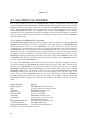
Example 1: A typical list file for a bootable fixed disk is shown below:
PROMDISK List File
[BOOT SOURCE]
b:
[SYSTEM]
io.sys
msdos.sys
command.com
[\]
autoexec.bat
config.sys
[\myproject]
c:\myproject\myfile1.ext
d:\myfile2.ext
[\promdisk]
c:\pdiii\pdcreate.exe
c:\pdiii\pdformat.exe
[\promdisk\lists]
d:\data\als.lst
d:\data\johns.lst
PROMDISK Directory Structure
C:\
io.sys
msdos.sys
command.com
autoexec.bat
config.sys
\MYPROJECT
myfile1.ext
myfile2.ext
\PROMDISK
pdcreate.exe
pdformat.exe
\LISTS
als.lst
johns.lst
Note: It is mandatory to include parent directories first, e.g. in the above example [\PROMDISK]
must come before [\PROMDISK\LISTS].
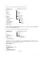
Example 2: A typical list file for a nonbootable floppy disk is shown below:
PROMDISK List File
[BOOT SOURCE]
c:
[\]
autoexec.bat
c:\project\myfile1.ext
d:\myfile2.ext
[\apps]
c:\doug\program1.exe
c:\daenah\program2.com
PROMDISK Directory Structure
C:\
autoexec.bat
myfile1.ext
myfile2.ext
\APPS
program1.exe
program2.com
If you do not have access to a text editor, you can use the standard DOS copy command to create the
PROMDISK list file. To create a PROMDISK list file named MYLIST.LST using the list of files from
example two above, at the DOS prompt you would type:
copy con mylist.lst
[boot source]
c:
[\]
autoexec.bat
c:\myproject\myfile1.ext
d:\myfile2.ext
[\apps]
c:\doug\program1.exe
c:\daenah\program2.com
^Z
(control Z)
11
Once you have created your PROMDISK list file, you can proceed to Section 4.2.2 to determine the size
and number of memory chips that will be required to emulate your specified drive.
If you choose to use the work disk method to specify your PROMDISK drive, you must first format a
floppy diskette using the version of DOS that your files require for operation. Be sure that the Format
Utility you use completely erases the diskette. If you are using DOS 5.0 FORMAT.EXE, be sure to use the
/U option. Also, if you are making a bootable PROMDISK drive A, be sure to transfer the system files
using the FORMAT /S option. You then copy the files you wish to emulate onto the newly formatted
work diskette. You can then proceed to Section 4.2.2 to determine the size and number of memory chips
that will be required to emulate your specified drive.
Note: The work disk method cannot be used to create a PROMDISK fixed disk drive.
4.2.2 Sizing the PROMDISK
Use the size option of the PROMDISK utility PDCREATE.EXE to determine the size and number of chips
required for emulation.
Example 1: To determine the number of chips required to emulate the files specified by your PROMDISK
list file named MYFILES.LST located on your drive B, type:
PDCREATE B:MYFILES SIZE
Notes:
1. DO NOT add an extension to the list file filename. PDCREATE assumes the extension .LST.
2. Because PROMDISK optimizes the file allocation table to match the size of memory chips are
used, you should specify the number and size of the chips you plan to use for an exact sizing.
Example 2: To determine the number of chips required to emulate the files specified by your PROMDISK
work disk located on your drive B, type:
PDCREATE B SIZE
Note: DO NOT add a colon after the drive letter when sizing a work disk.
The PROMDISK sizer will report the type, size, and number of chips required for drive emulation.
4.2.3 Programming the FLASH EPROMs
Use the PROMDISK Programming Utility PDCREATE.EXE to program the FLASH EPROMs. Be sure to
set DIP switch SW1-9 and SW1-10 to the ON position to enable the programming feature. These
switches may be left ON for normal operation including programming, or may be switched to the OFF
position after programming to prevent accidental programming of the chips.
Using the size information from Section 4.2.2 above, program the FLASH EPROMs by typing:
PDCREATE source numChips kSize destfile [pddrive]
Where:
source is the location and name of the list file (no extension) or the location of the work diskette.
numChips is the number of chips from Section 4.2.2.
kSize is size of the chip(s) in K-bytes, i.e. 64, 128, 256, or 512.
12
destFile enter Flash for Intel/AMD 28F010/020 Flash EPROMs, AMD for AMD 29F040 Flash
EPROMS, SST for SST Flash EPROMS, or output filename without extension to create the binary images.
pddrive PROMDISK drive to program, i.e. A, B, C, etc.
options:
/dN = Use DOS to read floppy (0 = no, <1 >= yes)
/hN = Fixed disk partition (0 = no, <1 >= yes)
/pN = Pause before reading disk (0 = no, <1> = yes)
/sN = Presize before writing (0 = no, <1 >= yes)
/vN = Verbose setting (0, <1>, or 2)
Note: DO NOT add an extension to the destFile filename. PDCREATE adds the extension .PD1, .PD2,
etc.
The PDCREATE program will check to see if the FLASH EPROMs are erased, erase them if necessary,
and program them accordingly. After the chips are programmed, PDCREATE will prompt you to reboot
the computer to initialize the PROMDISK drive.
Example 1: To build a 512K PROMDISK fixed disk drive C using four FLASH 128Kx8 chips from your
list file named MYFILES.LST located in drive A, type:
PDCREATE A:MYFILES 4 128 FLASH C
Example 2: To build a 512K PROMDISK drive B using two FLASH 256Kx8 chips from your work disk
located in drive A, type:
PDCREATE A 2 256 FLASH B
4.2.4 Programming 5V-Only FLASH EPROMs
There are two types of 5V-only Flash EPROMs currently on the market today; AMD and SST. The
program operation is the same as the standard Intel/AMD 28F010/020 Flash.
Example: To build a 2M-byte PROMDISK fixed disk drive C using four AMD 5V-only FLASH 512Kx8
chips from your list file BIGPD.LST located in drive A, you type:
PDCREATE A:BIGPD 4 512 AMD C
4.2.5 Programming Standard EPROMs
Standard EPROMs must be programmed from an external EPROM programmer using the binary image
file(s) created with the PROMDISK PDCREATE.EXE Programming Utility before installing them on the
PROMDISK board. The procedure for creating binary image file(s) is the same as the procedure for
programming FLASH EPROMs (Section 4.2.3 above) except that an output filename is specified instead
of the word "FLASH". After programming the EPROMs with an external EPROM programmer, they
must be installed on the board in accordance with Sections 3 and 5 of this manual before installing the
board in your target system.
Example 1: To create the binary image file(s) named MYIMAGE.PDx for a 512K PROMDISK drive B
using 4 128Kx8 EPROMs from your PROMDISK list file named MYFILES.LST located in drive A, type:
13
PDCREATE A:MYFILES 4 128 MYIMAGE B
Example 2: To create the binary image file for a 128K PROMDISK drive B using one 128Kx8 EPROM from
your PROMDISK work disk located in drive A, type:
PDCREATE A 1 128 MYIMAGE B
Example 3: To create the binary image file(s) named MYIMAGE.PDx for a 512K PROMDISK fixed disk
drive C using 4 128Kx8 EPROMs from your PROMDISK list file named MYFILES.LST located in drive A,
type:
PDCREATE A:MYFILES 4 128 MYIMAGE C
The build program will create the binary images for the files specified in your file list and write the
images to the selected filename. The selected filename extension .PDx will be incremented for each chip
in the set.
4.2.6 Programming the EPROM Drive A
When PROMDISK is configured as drive A, your system will automatically try to boot from PROMDISK.
If the PROMDISK drive A is corrupted or erased your system will hang-up. If you are using standard
EPROMs you must remove the EPROMs and reprogram them. If you are using FLASH EPROMs, you
can reprogram them on-board by first configuring PROMDISK for another valid drive, typically drive B,
and rebooting the system using a physical drive. Once the system is rebooted, you can program the
FLASH EPROMs. After the FLASH EPROMs are reprogrammed, reconfigure PROMDISK as drive A, and
then reboot the system.
If this procedure presents a problem in your particular application, you might consider emulating a
fixed drive C which will always allow you to boot from a physical floppy disk if installed. Otherwise
consider the following:
1. Configure PROMDISK as drives A & B.
2. Use standard EPROMs for drive A, and FLASH EPROMs for B.
3. Place DOS, your start-up files, and PDCREATE.EXE in drive A.
4. Place your application and files subject to change in drive B.
This approach insures that you will always be able to boot your system since the operating system and
start-up files are in standard EPROM.
4.3 EMULATING FLOPPY DRIVES C THROUGH Z
Some applications may require emulating a floppy disk drive C or above. When emulating floppy disk
drives C through Z in systems that do not allow floppy disks to be configured for these drives or in
systems with hard disks, you must specify the DOS device driver DRIVER.SYS in your CONFIG.SYS file.
The CONFIG.SYS and DRIVER.SYS files must be contained in the root directory of your boot drive.
Example 1: To configure your system with physical disks for drives A and B and a PROMDISK drive C,
you must first set the configuration of your system CMOS or DIP switch to define floppy disks installed
14
for drives A and B, and NONE installed for drives C and D. Next, you make a CONFIG.SYS file
containing the following:
DEVICE = DRIVER.SYS
/d:2
Example 2: To configure your system with a physical disk for drive A and PROMDISK drives B, C, D, you
must first set the configuration of your system CMOS or DIP switch to define a physical floppy disk
installed for drive A and NONE installed for drives B through D. Next, you make a CONFIG.SYS file
containing the following:
DEVICE = DRIVER.SYS
DEVICE = DRIVER.SYS
/d:2
/d:3
Notes: The above device drivers are only used when emulating floppy disks "C" and above.
4.4 DYNAMIC DRIVE ASSIGNMENT
The PROMDISK board supports dynamic drive assignments for its three drives. This feature is
extremely useful during the development stages when the PROMDISK board is installed in a
development system with a different drive configuration than the final target system. The
PDASSIGN.COM software utility allows the user to reassign or even hide the PROMDISK drives. The
format for PDASSIGN is shown below:
PDASSIGN {oldDrive}={newDrive}
Where:
{oldDrive} is the PROMDISK drive you wish to reassign.
{newDrive} is the letter A through Z for the new PROMDISK drive. Entering a dash (-) will hide the
drive until the system is rebooted.
Notes:
1. PROMDISK fixed disk drives cannot be reassigned.
2. The reassign feature is disabled when the system is rebooted.
Example 1: To reassign PROMDISK drive A to B, type:
PDASSIGN A=B
Example 2: To reassign PROMDISK drive B to A, type:
PDASSIGN B=A
Example 3: To hide PROMDISK drive A, type:
PDASSIGN A=-
15
The following is a typical application example:
The PROMDISK board is configured as ABC. Drive A contains DOS, Drive B the application program,
and Drive C the data files. To protect the application program on Drive B, you would execute
PDASSIGN B=- from within the application program or from the DOS prompt. This would cause the
PROMDISK Drive B to be inaccessible, and the physical Drive B, if installed, to be accessible.
4.5 PROMDISK CUSTOM FEATURES
The PROMDISK control firmware can be customized to include custom drive configurations and/or
small setup or user defined control programs which can be executed as part of the start-up procedure
just prior to the boot process. Contact the factory for more information concerning these custom features.
16
SECTION 5 - FLASHCOM
FlashCom is a firmware package designed to work with MCSI's PROMDISK Disk Emulator Board. The
package can be used for two basic functions:
• Remote downloading/programming of PROMDISK Flash Memory
• Remote download and execution of special software out of the remote embedded PC's DRAM without
modifying PROMDISK (this feature is for future expansion by MCSI or the OEM)
For both of these tasks, FlashCom utilizes a special program on the embedded PC which resides in
MCSI's PROMDISK firmware EPROM at location U9 on the board. If you choose this feature, the
PROMDISK firmware EPROM must be reprogrammed from the applicable file located in the FlashCom
subdirectory on the PROMDISK distribution diskette. The FlashCom files for COM1 and COM2
operation are shown below:
EPROM Location
PROMDISK IV U9
COM1 File
FC1-PD4.BIN
COM2 File
FC2-PD4.BIN
When FlashCom is installed, it is automatically each time the embedded PC system is booted during
ROMSCAN. FlashCom first checks the Data Set Ready (DSR) Modem Status Line for the selected COM
port, if it is active, then is monitors the port for a preset length of time at BAUD rates from 9600 to 115000.
If a valid startup message is received, the software sets itself up for performing one of the above remote
tasks, if a valid start-up message is not received it passes control back to the BIOS.
5.1 HOW DOES FLASHCOM OPERATE?
What FlashCom does is determined by the commands it receives over the serial port. Commands include
the ability to copy RS-232 received data to the PC's conventional memory and to transfer control to the
received data. This protocol is used by the MCSI supplied Flash update software run on an external
DOS compatible PC, which would typically be a notebook or laptop computer. As of the writing of this
manual, the Flash update software is the only utility that uses this protocol, but future utilities are
planned. The technical specifications of the protocol are available from MCSI for OEMs wanting to write
their own downloadable programs. Please contact MCSI for more information.
FlashCom also includes two utility programs, PUTFILE and GETFILE, that allow transferring files
between two computers. These are generic programs which you may also find useful in other embedded
situations.
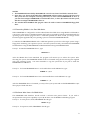
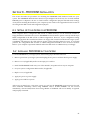
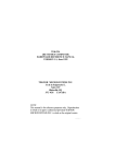
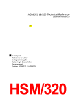
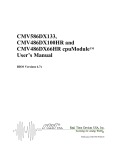
5.2 FLASHCOM COMPONENTS
The core FlashCom package consists of four components -- RS-232 uploading firmware, a Flash
programming module, a remote communications module, and a control program for the host portable
computer. For maximum flexibility, only the FlashCom firmware is kept on the embedded PC. The other
three programs are kept on the host PC. The diagram on the following page shows the relationship
between these four files.
17
HOST COMPUTER
REMOTE COMPUTER
FlashCom firmware
on PROMDISK/SBC.
UPLOAD.EXE
<-RS-232
PACKETS->
Secondary host
file transfer program
used by UPLOAD.
Secondary remote
Flash programming
utility downloaded
by the host PC.
The actual file names are listed below.
File
SENDEXE.EXE
UPLOAD.EXE
GPUPLOAD.EXE
PD4AMD.BIN
PD4INT.BIN
PD4SST.BIN
PUTFILE.EXE
GETFILE.EXE
PDCREATE.EXE
Purpose
Primary control program to send .exe file to execute in remote PC.
Primary control program
Secondary program used by UPLOAD that reads .PD* files and sends them to
the remote PC.
Flash programming program for AMD 29F040 Flash EPROMs
Flash programming program for Intel/AMD 28F010/020 Flash EPROMs
Flash programming program for SST 28F040 Flash EPROMs
File transfer software (sending side)
File transfer software (receiving side)
PROMDISK Programming Utility
The two primary programs, UPLOAD.EXE and the PROMDISK/FlashCom firmware, establish
communication via the serial port and then transfer control to secondary programs using a pre-defined
protocol.
PUTFILE and GETFILE are simple general purpose file transfer programs for the COM ports. These files
are not required for FlashCom, and are supplied as convenient utilities.
5.2.1 UPLOAD
The host computer control program is a DOS based command-line driven program. It is designed much
like the small FlashCom driver in that once it downloads the remote program, it leaves the rest of the
work to a separate .EXE program which it runs using a DOS shell. A sample command line to program
Intel/AMD 28F020 Flash EPROMS is shown below:
UPLOAD 1 115000 PD4INT.BIN GPUPLOAD APNAME.PD1 2 256 1
The first two parameters list the COM port number followed by the BAUD rate which can be any
standard DOS BAUD rate from 9600 to 115000. Unless you are experiencing problems, we recommend
115000 BAUD. The second two parameters list the names of the "real" programs that take care of
transferring the PROMDISK data and programming the 28F010/020 Flash parts -- in this case
PD4INT.BIN and GPUPLOAD.EXE (.EXE extension assumed).
For programming AMD 29F040 Flash parts, the following command would be used:
UPLOAD 1 115000 PD4AMD.BIN GPUPLOAD APNAME.PD1 2 512 1
18
The *.PDx files will be programmed into the remote Flash parts and each sector will be sent with a
checksum to detect anomalies in the transmission process. The embedded PC will also report back any
problem programming the Flash parts which will cause the sending program to stop and display an
error message. You can tell by looking at the line above the error message which chip did not program.
5.2.2 UPLOAD PROGRAMMING AND VERIFICATION OPTIONS
To insure that all of the binary images were successfully programmed, you may want to perform a final
read back step. To do this, add "/PV" at the end of the command line when you run UPLOAD.EXE. A
complete byte-for-byte verification will be performed after all of the chips have been programmed.
To verify only, add "/V" instead of "/PV." This will not erase or program the Flash parts, but will rather
compare their contents with a set of *.PDx files stopping when an anomaly is found. This is a quick
method of determining if an embedded PC has the latest set of PROMDISK images.
5.3 GENERAL PURPOSE RS-232 FILE TRANSFER PROGRAMS
Beyond transferring complete PROMDISK images with FlashCom, it may be necessary or "convenient" to
copy individual files -- either to an SRAM PROMDISK drive, an MS-DOS RAM drive, or to the Flash File
System. Two MCSI utility programs GETFILE and PUTFILE are supplied to support this requirement.
One is run on the sending side and one is sent to the receiving side.
5.3.1 USING PUTFILE
PUTFILE.EXE reads files on the host computer and sends them using a "FlashCom-like" protocol out
either COM1 or COM2. It is invoked by specifying the COM port, the BAUD rate, and a filename which
can contain wild cards (* or ?). Enter PUTFILE with no arguments at the DOS prompt for more detailed
explanations. An example command is shown below.
PUTFILE 1 115000 APREVX1.EXE
Since it is impossible to know the speed of the remote disk the data is eventually being copied to, the
PUTFILE program does not time-out. It will exit after copying the last file. You can also exit early by
pressing the <Esc> key.
5.3.2 USING GETFILE
GETFILE.EXE responds to messages from PUTFILE.EXE and creates new files as specified. The date and
time of the file will not be as originally sent, but will match the remote computer's date and time at the
instant the file was transferred.
To invoke GETFILE, specify the COM port number and BAUD rate -- optionally followed by a time-out
from 5 to 30 seconds. If no time-out is specified, the time-out will default to 15 seconds. An example
command is shown below:
GETFILE 1 115000 30
GETFILE will exit on its own if (A) a command from the host is received telling it there are no more files,
(B) if no message is received from the host in the specified time-out, or (C) if a message is received out of
synchronization. As with the PUTFILE program, you can also abort early by pressing the <Esc> key.
19
5.4 OTHER USES FOR FLASHCOM
The basic portion of FlashCom embedded in the PROMDISK firmware essentially does only four things - synchronize on a BAUD rate, copy blocks of data from the serial port to memory, copy blocks of data
from memory to the serial port, and jump to an address in memory. This allows the architecture to be
used for much more than updating Flash EPROMs. The SENDEXE.EXE program is used to download a
“.exe” program and run it out of memory without modifying the code in PROMDISK.
The following files are provided as examples:
TEST.ASM
TEXT.BIN
T.BAT
Sample of user assembly source code
Sample executable test program
File to convert .exe to .bin
The above sample test program can be sent and executed in the target FlashCom system by entering the
following on the host system and rebooting the target system:
SENDEXE 1 115000 TEST.BIN
20
SECTION 6 - PROMDISK INSTALLATION
This section describes the procedures for installing the PROMDISK Disk Emulator board into your
system. The PROMDISK Disk Emulator board was preconfigured at the factory for use with standard
EPROMs prior to shipment. Be sure to check both the configuration jumpers and DIP switch settings
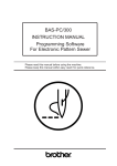
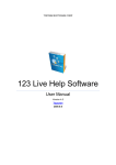
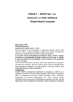
closely before installing the board into your computer system. Refer to the Appendix B for the location of
the configuration DIP switch and configuration jumpers.
6.1 SETTING UP YOUR SYSTEM FOR PROMDISK
Some computers have a configuration DIP switch or CMOS memory to set the maximum number of
floppy disk drives attached to the system. PROMDISK has been found to operate correctly with all major
BIOSs, independent of the DIP switch or CMOS configuration. However, if your configuration setting
defines a floppy disk drive installed and there is no floppy disk controller installed in the target system,
some BIOSs will attempt to do a disk seek test causing a rather long delay during boot-up. To avoid this
problem, the configuration DIP switches or CMOS configuration should be set to No Drives Installed.
Refer to your computer's Operations Manual and set the DIP switch or CMOS memory accordingly.
6.2 INSTALLING PROMDISK IN YOUR SYSTEM
To install PROMDISK in your target system, the following steps should be followed:
1. Remove power from your target system and unplug the AC power cord from the DC power supply.
2. Remove cover (if applicable) and locate an empty I/O card slot.
3. Install the PROMDISK board in any one of the unused I/O expansion slots in your computer.
4. Set your system's configuration DIP switches, if applicable.
5. Replace cover, if applicable.
6. Apply AC power to power supply.
7. Apply power and boot system.
After power is turned on to your target system, you will see the PROMDISK sign-on message for each
drive emulated. Read-Only drives using EPROMs and/or FLASH EPROMs can be accessed
immediately, whereas Read/Write drives using SRAMs or NVRAMs will not be initially recognized
until properly formatted.
21
APPENDIX A - SPECIFICATIONS
This appendix lists the specifications for the PROMDISK Disk Emulator board.
Memory:
Disk Emulator:
BIOS:
I/O Bus:
DMA:
Timers:
Interrupts:
I/O Ports:
Battery:
Size:
Power:
22
PROMDISK DISK EMULATOR SPECIFICATIONS
4M-bytes total (Memory Chips Not Included). Eight 28/32 pin JEDEC Standard Sockets.
Access Time: 150 nanoseconds maximum
Chip Types: EPROMs, FLASH EPROMs, SRAMs, or NVRAMs.
Emulates up to three floppy or fixed disk drives
On-board BIOS extension firmware.
IBM PC/XT/AT Compatible 62-pin Edge Connector
Not Used
Not Used
Not Used
Not Used
Lithium for CMOS SRAM (five years operation under typical conditions)
Half size XT board 6.8"L X 4.2"H
+5VDC @ 0.080A, +12VDC @ 0.040A
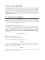
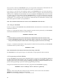
E1
1
U9
U1
MCSI PROMDISK
Firmware
U1-U4 Jumpers
E7
U5-U7Power
Select
U6
U8 Jumpers
E3
Address/Drive/Write
DIP Switch
U5-U7 Jumpers
1
1
1
1
E6
U5
2
U4
2
E5
U3
2
U2
E4
(External
Battery Jumper)
U7
U8
Lithium
Battery
U1-U4 Power
Select
1
E2
U8 Power
Select
APPENDIX B - PROMDISK IV JUMPER LOCATIONS
23
APPENDIX C - ROMSCAN ADDRESS SETTINGS
24
APPENDIX D - PROMDISK DRIVE CONFIGURATIONS
25
APPENDIX E - PROMDISK MEMORY SELECTION JUMPERS
26