1
Chapter 4. Firmware Development
48
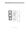
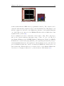
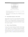
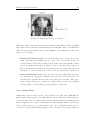
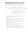
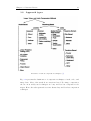
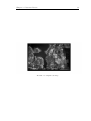
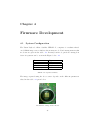
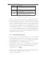
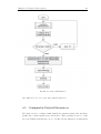
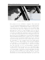
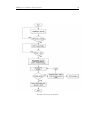
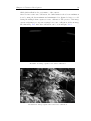
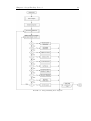
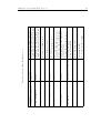
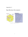
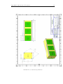
Figure 4.9: GUI for Vision Payload
These parameters are sent to the FPGA for configuration. These variables will
be processed in various sub functions in the program, before sending the updated
configuration parameters to the FPGA The image acquisition operation can be performed anytime after the successful configuration of the sensor & FPGA. Taking
reference from the these values, sensor configuration is set and the corresponding
image with respect to the mode of operation and number of slot to store the captured image is processed. Next, the data for the Fixed Pattern Noise (FPN) is
loaded and stored in an FPN buffer myByteBuffer2, details on how the FPN values
are obtained will be discussed in the later section. The digitized raw data of the
image is then read from the SDRAM and stored in another buffer myByteBuffer
using the ReadFromBlockPipeOut() function explained earlier. Noise cancellation
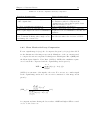
of the data is performed by subtracting the FPN values from the obtained raw
data and the new image without noise is obtained. As these values are in 12 bits,
the operations have to be done on a high byte and a low byte, which requires 2
elements for both arrays. Thus bit shifting operations and address assignments
to the values have to be performed during the noise cancellation. In addition,
the obtained values after noise cancellation cannot be outside the 12 bit (0-4095)
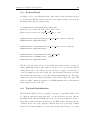
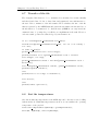
range. These values will be set to the corresponding minimum or maximum values. The algorithm is shown below, where by a for loop is called with the number
of pixels set as a loop count (c0) limit . The retrieved values from the FPGA,
stored in myByteBuffer, is being subtracted with the myByteBuffer2. The higher
bytes of the 2 arrays are multiplied by 256, which is equivalent to an 8 bit left
shift, while the lower bytes are kept at their original value. After the computation,
the final value is stored in the variable myInt, which will be processed to set all