1
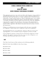
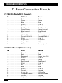
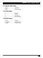
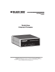
NOVEMBER 2003
AC098A
Video Scan Converter Plus
lus
verter P
an Con
c
Video S
ZOOM
INPUT
ANTIR
FLICKE
FREEZE
TEST
POWER
CUSTOMER
SUPPORT
INFORMATION
Order toll-free in the U.S.: Call 877-877-BBOX (outside U.S. call 724-746-5500)
FREE technical support 24 hours a day, 7 days a week: Call 724-746-5500 or fax 724-746-0746
Mailing address: Black Box Corporation, 1000 Park Drive, Lawrence, PA 15055-1018
Web site: www.blackbox.com • E-mail: [email protected]
FCC AND IC RFI STATEMENTS
FEDERAL COMMUNICATIONS COMMISSION
AND
INDUSTRY CANADA
RADIO FREQUENCY INTERFERENCE STATEMENTS
This equipment generates, uses, and can radiate radio frequency energy and if not
installed and used properly, that is, in strict accordance with the manufacturer’s
instructions, may cause interference to radio communication. It has been tested
and found to comply with the limits for a Class A computing device in accordance
with the specifications in Subpart B of Part 15 of FCC rules, which are designed
to provide reasonable protection against such interference when the equipment
is operated in a commercial environment. Operation of this equipment in a
residential area is likely to cause interference, in which case the user at his own
expense will be required to take whatever measures may be necessary to correct
the interference.
Changes or modifications not expressly approved by the party responsible
for compliance could void the user’s authority to operate the equipment.
This digital apparatus does not exceed the Class A limits for radio noise emission from
digital apparatus set out in the Radio Interference Regulation of Industry Canada.
Le présent appareil numérique n’émet pas de bruits radioélectriques dépassant les limites
applicables aux appareils numériques de la classe A prescrites dans le Règlement sur le
brouillage radioélectrique publié par Industrie Canada.
The Video Scan Converter Plus conforms to the following standards:
EMC EN 55022: 1994, CISPR 22: 1993, Class A Limit;
EN50082-1:1992;
IEC 801-2:1991;
IEC 801-3:1984;
IEC 801-4: 1988
1
VIDEO SCAN CONVERTER PLUS
NORMAS OFICIALES MEXICANAS (NOM)
ELECTRICAL SAFETY STATEMENT
INSTRUCCIONES DE SEGURIDAD
1. Todas las instrucciones de seguridad y operación deberán ser leídas antes de
que el aparato eléctrico sea operado.
2. Las instrucciones de seguridad y operación deberán ser guardadas para
referencia futura.
3. Todas las advertencias en el aparato eléctrico y en sus instrucciones de
operación deben ser respetadas.
4. Todas las instrucciones de operación y uso deben ser seguidas.
5. El aparato eléctrico no deberá ser usado cerca del agua—por ejemplo, cerca
de la tina de baño, lavabo, sótano mojado o cerca de una alberca, etc..
6. El aparato eléctrico debe ser usado únicamente con carritos o pedestales que
sean recomendados por el fabricante.
7. El aparato eléctrico debe ser montado a la pared o al techo sólo como sea
recomendado por el fabricante.
8. Servicio—El usuario no debe intentar dar servicio al equipo eléctrico más allá
a lo descrito en las instrucciones de operación. Todo otro servicio deberá ser
referido a personal de servicio calificado.
9. El aparato eléctrico debe ser situado de tal manera que su posición no
interfiera su uso. La colocación del aparato eléctrico sobre una cama, sofá,
alfombra o superficie similar puede bloquea la ventilación, no se debe colocar
en libreros o gabinetes que impidan el flujo de aire por los orificios de
ventilación.
10. El equipo eléctrico deber ser situado fuera del alcance de fuentes de calor
como radiadores, registros de calor, estufas u otros aparatos (incluyendo
amplificadores) que producen calor.
11. El aparato eléctrico deberá ser connectado a una fuente de poder sólo del
tipo descrito en el instructivo de operación, o como se indique en el aparato.
2
NOM STATEMENT
12. Precaución debe ser tomada de tal manera que la tierra fisica y la polarización
del equipo no sea eliminada.
13. Los cables de la fuente de poder deben ser guiados de tal manera que no
sean pisados ni pellizcados por objetos colocados sobre o contra ellos,
poniendo particular atención a los contactos y receptáculos donde salen
del aparato.
14. El equipo eléctrico debe ser limpiado únicamente de acuerdo a las
recomendaciones del fabricante.
15. En caso de existir, una antena externa deberá ser localizada lejos
de las lineas de energia.
16. El cable de corriente deberá ser desconectado del cuando el equipo
no sea usado por un largo periodo de tiempo.
17. Cuidado debe ser tomado de tal manera que objectos liquidos
no sean derramados sobre la cubierta u orificios de ventilación.
18. Servicio por personal calificado deberá ser provisto cuando:
A: El cable de poder o el contacto ha sido dañado; u
B: Objectos han caído o líquido ha sido derramado dentro del aparato; o
C: El aparato ha sido expuesto a la lluvia; o
D: El aparato parece no operar normalmente o muestra un cambio
en su desempeño; o
E: El aparato ha sido tirado o su cubierta ha sido dañada.
3
VIDEO SCAN CONVERTER PLUS
TRADEMARKS
IBM is a registered trademark of International Business Machines Corporation.
Mac and Macintosh are registered trademarks of Apple Computer, Inc.
Any other trademarks mentioned in this manual are acknowledged to be the property of the
trademark owners.
4
CONTENTS
Contents
Chapter
Page
1. Specifications. . . . . . . . . . . . . . . . . . . . . . . . . . . . . . . . . . . . . . . . . . . . . . . . 7
2. Introduction . . . . . . . . . . . . . . . . . . . . . . . . . . . . . . . . . . . . . . . . . . . . . . . . 8
2.1 Description . . . . . . . . . . . . . . . . . . . . . . . . . . . . . . . . . . . . . . . . . . . . . 8
2.2 What the Package Includes . . . . . . . . . . . . . . . . . . . . . . . . . . . . . . . . 8
2.3 Additional Items You May Need . . . . . . . . . . . . . . . . . . . . . . . . . . . . 8
3. Installation. . . . . . . . . . . . . . . . . . . . . . . . . . . . . . . . . . . . . . . . . . . . . . . . . . 9
3.1 Installation Steps . . . . . . . . . . . . . . . . . . . . . . . . . . . . . . . . . . . . . . . . 9
3.2 Available Outputs . . . . . . . . . . . . . . . . . . . . . . . . . . . . . . . . . . . . . . . . 9
3.3 Sync Types Supported . . . . . . . . . . . . . . . . . . . . . . . . . . . . . . . . . . . 10
3.4 Video Standard Selection . . . . . . . . . . . . . . . . . . . . . . . . . . . . . . . . 10
3.5 Remote Control . . . . . . . . . . . . . . . . . . . . . . . . . . . . . . . . . . . . . . . . 10
4. Operation . . . . . . . . . . . . . . . . . . . . . . . . . . . . . . . . . . . . . . . . . . . . . . . . . 11
4.1 Diagnostic LEDs . . . . . . . . . . . . . . . . . . . . . . . . . . . . . . . . . . . . . . . . 11
4.2 VGA and Mac Resolutions Supported . . . . . . . . . . . . . . . . . . . . . . 11
4.3 How to Activate Test Signals . . . . . . . . . . . . . . . . . . . . . . . . . . . . . . 11
4.4 Color Bars When Test is Not Activated. . . . . . . . . . . . . . . . . . . . . . 11
4.5 Sizing the Image . . . . . . . . . . . . . . . . . . . . . . . . . . . . . . . . . . . . . . . . 12
4.6 Reducing Flicker in the Image . . . . . . . . . . . . . . . . . . . . . . . . . . . . 12
4.7 Freezing the Image on Your Video Screen. . . . . . . . . . . . . . . . . . . 13
4.8 Positioning the Image on the Screen . . . . . . . . . . . . . . . . . . . . . . . 13
4.9 Returning to Factory-Default Settings. . . . . . . . . . . . . . . . . . . . . . . 14
4.10 Locking the Key Panel . . . . . . . . . . . . . . . . . . . . . . . . . . . . . . . . . . . 14
5. Tips for Improving Your Converted Computer Images. . . . . . . . . . . . . 15
5.1 Know What Your Converted Image Will Look Like . . . . . . . . . . . 15
5.2 Use Black and White . . . . . . . . . . . . . . . . . . . . . . . . . . . . . . . . . . . . 15
5.3 Avoid Intense Colors . . . . . . . . . . . . . . . . . . . . . . . . . . . . . . . . . . . . 16
5.4 Use High-Grade Video Tape . . . . . . . . . . . . . . . . . . . . . . . . . . . . . . 16
5.5 Pay Attention to Your Borders. . . . . . . . . . . . . . . . . . . . . . . . . . . . . 16
5.6 Eliminate Flicker . . . . . . . . . . . . . . . . . . . . . . . . . . . . . . . . . . . . . . . 16
5.7 Use S-Video . . . . . . . . . . . . . . . . . . . . . . . . . . . . . . . . . . . . . . . . . . . . 17
5
VIDEO SCAN CONVERTER PLUS
Contents (continued)
Chapter
Page
6. Troubleshooting . . . . . . . . . . . . . . . . . . . . . . . . . . . . . . . . . . . . . . . . . . . . 18
6.1 Problems/Solutions . . . . . . . . . . . . . . . . . . . . . . . . . . . . . . . . . . . . . 18
6.2 Calling Black Box . . . . . . . . . . . . . . . . . . . . . . . . . . . . . . . . . . . . . . . 19
6.3 Shipping and Packaging . . . . . . . . . . . . . . . . . . . . . . . . . . . . . . . . . 19
7. Rear Connector Pinouts . . . . . . . . . . . . . . . . . . . . . . . . . . . . . . . . . . . . . . 20
7.1 VGA Out/Mac In (HD15 Connector) . . . . . . . . . . . . . . . . . . . . . . 20
7.2 VGA In/Mac Out (DB15 Connector). . . . . . . . . . . . . . . . . . . . . . . 20
7.3 Composite Video Output. . . . . . . . . . . . . . . . . . . . . . . . . . . . . . . . . 21
7.4 S-Video Output . . . . . . . . . . . . . . . . . . . . . . . . . . . . . . . . . . . . . . . . . 21
7.5 RS-232 Remote . . . . . . . . . . . . . . . . . . . . . . . . . . . . . . . . . . . . . . . . . 21
6
CHAPTER 1: Specifications
1. Specifications
Input Sampling: 24-bit (8 bits per RGB) support for 16.8 million colors
Input Sync Types Supported: Separate H & V, composite sync (with or without
separation), sync-on-green
Resolution: Up to 1280 x 1024 @ 60 Hz
System Requirements: IBM® PC compatible or Macintosh® computer;
NTSC or PAL monitor
Video Memory: 720 x 740 x 16 bits
Video Output: NTSC or PAL (switch-selectable); composite and S-Video
Zoom/Shrink Ratios: 5
CE Approval: Yes
Connectors: Inputs: VGA: DB15 female; Mac®: HD15 female;
Outputs: VGA: HD15 female; Mac: DB15 female;
S-Video: 4-pin mini-DIN female; Composite: BNC female
Power: 100–250 VAC, 47–63 Hz
Size: 1.5"H x 7.3"W x 11"D (3.8 x 18.5 x 27.9 cm)
7
VIDEO SCAN CONVERTER PLUS
2. Introduction
2.1 Description
The Video Scan Converter Plus lets you convert your high-resolution computer
video into a form suitable for recording on a VCR, displaying on a conventional
TV or video monitor, or integrating into a multimedia production system. The
Video Scan Converter Plus does not require any special software and operates
completely externally from your computer.
We recommend that you read Chapter 5. It provides some useful suggestions for
obtaining the best possible image from your Video Scan Converter Plus. It also
explains what you should expect, in terms of image quality, when your computer
images are recorded on a VCR or displayed on a conventional video monitor or
TV.
2.2 What the Package Includes
• (1) Video Scan Converter Plus
• (1) 12-ft. (3.7-m) composite video output cable (BNC male to BNC male)
• (1) BNC female to RCA male adapter
• (1) 12-ft. (3.7-m) S-Video output cable (4-pin DIN male to 4-pin DIN male)
• (1) 6-ft. (1.8-m) computer-to-converter input cable (HD15 male to DB15 male)
• (2) Fuses
• (1) Term block connector
• (1) AC power cord
• This user’s manual
If anything is missing or damaged, please contact Black Box at 724-746-5500.
2.3 Additional Items You May Need
You might also need:
• RF modulator for North America channels 3 and 4
• AC line cords for North America, Japan, UK, Europe, or Australia
• Rackmounting kits
8
CHAPTER 3: Installation
3. Installation
3.1 Installation Steps
Follow these steps to install the converter:
1. Disconnect your monitor from the monitor port on your PC.
2. Using the reversible 6-ft. (1.8-m) input cable provided with the converter,
connect one end to the monitor port on your computer and the other end
to the connector on the rear panel of the converter marked either VGA In
or Mac In.
3. Connect your monitor, if you have one, to the converter’s connector labeled
VGA Out or Mac Out. Use the cable that is attached to your monitor.
4. Connect the AC line cord provided with the converter to the connector
labeled Power. Plug the AC line cord into the wall outlet to provide power.
5. Connect the converter’s video or S-video output to your video equipment.
If desired, you may use both outputs simultaneously.
6. Complete the installation by turning your computer on, if it is not on already.
The front-panel green LED labeled Input should light, indicating that the
unit is receiving a valid signal from the computer.
3.2 Available Outputs
• Composite: This is a single composite video signal and is compatible with the
“video” input on consumer TVs, monitors, and VCRs, as well as on all
professional video equipment. It cannot be connected to the antenna input.
• S-Video: This is an advanced form of video in which the brightness and color
parts of the image are actually on two separate signals. This signal is sometimes
called S-VHS, S-Video, or Y/C. It is also compatible with the Hi-8 and Beta-ED
standards. Using this output will result in a better-quality picture than using
the video output.
NOTE
Both outputs are available for use at the same time. Unused outputs
do not have to be terminated if they are not being used.
9
VIDEO SCAN CONVERTER PLUS
3.3 Sync Types Supported
The Video Scan Converter Plus will automatically lock to any one of three different
sync types: separate H&V, composite sync, and sync-on-green.
3.4 Video Standard Selection
• NTSC/PAL: This switch selects the video timing standard to be used for the
video and S-video outputs. NTSC is the standard for the USA, Canada, Mexico,
Japan, and parts of South America. PAL is used throughout most of Europe,
the Middle East, Southern Asia, and the Pacific Rim.
3.5 Remote Control
The converter provides for a hard-wired RS-232 remote-control connection using
a 3-pin Phoenix-type connector on the rear panel. The baud rate is 9600 baud,
no parity, 1 start bit, and 1 stop bit. The pinout is as follows:
1-Ground
2-Receive Data
3-Transmit Data
Contact Black Box Technical Support at 724-746-5500 for detailed specifications
on the command structure for this remote control port.
10
CHAPTER 4: Operation
4. Operation
The Video Scan Converter Plus not only offers high performance and reliability,
but also provides an extremely easy, intuitive user interface. However, in order to
fully understand how the converter operates and to take advantage of all of its
features, we suggest that you read this entire section. If, after becoming familiar
with the unit’s operation and features, you still have questions, call Black Box
Technical Support at 724-746-5500.
4.1 Diagnostic LEDs
• Power: This indicator tells when power is present and the converter is ON.
If this light is glowing dim or not at all, it indicates that something might be
wrong with the internal power supply.
• Input: This indicator tells when a valid computer signal is present at the VGA
In or Mac In connector on the rear panel.
4.2 VGA and Mac Resolutions Supported
The converter will support any resolution having a horizontal sync frequency
within the range of 31 to 71 kHz. Generally, this will include PCs up to 1280 x 1024
at 60 Hz. Interlaced resolutions are not supported.
4.3 How to Activate Test Signals
The Test button will force the converter to generate a test signal on its composite
and S-Video outputs. Press the button once and the unit will generate color bars.
Press it again to turn off the test generator. The green LED on the Test button
indicates when the test-pattern generator is in operation.
4.4 Color Bars When the Test Is Not Activated
From time to time, your converter may output color bars even though you have not
pushed the Test key on the front panel. If your unit is generating color bars but
the LED on the Test key is not lit, either there is no input signal from the
computer or the input signal from the computer is not in a resolution or mode
supported by the converter.
11
VIDEO SCAN CONVERTER PLUS
4.5 Sizing the Image
• Zoom: The zoom feature performs two important functions. First of all, it
provides an “underscan” function, which shrinks the image display both
horizontally and vertically by 15%. This ensures that no edges of your image
are lost beyond the borders of your screen when converted to a TV video
format. (TV pictures are designed to “bleed” off the screen, while images on
computer monitors typically have visible borders.)
Secondly, the zoom feature provides three settings that enlarge your image
display while also enhancing its resolution. By repeatedly pressing the zoom
button, you can cycle through the following different image sizes:
Zoom Ratio
Indicator LED
85%
100%
130%
160%
200%*
ON
OFF
ON
ON
ON
*The 200% zoom ratio may not be available at the highest input frequency.
• Zoom Shortcut Keys: In addition to cycling through the various zoom ratios,
the converter also provides the option to go directly to three of the zoom
settings using the following key combinations. You must push both keys
simultaneously to access this feature.
Zoom Ratio
Key Combination
85% (lowest zoom; “underscan mode”) ZOOM & ↓
100% (standard “overscan mode”)
ZOOM & →
200% (highest zoom mode)
ZOOM & ↑
4.6 Reducing Flicker in the Image
The Anti-Flicker button will activate one of four levels of flicker reduction. To turn
on the flicker filter, push the Anti-Flicker button once. This activates level one of
the filter. The green LED should light, indicating that this feature is now active.
Press the button repeatedly to cycle through levels two, three, and four of the
flicker filter. The green light will remain lit for all four stages. Pushing the button a
fifth time will turn off the flicker filter and extinguish the green LED.
12
CHAPTER 4: Operation
Try the different settings for this button to see which gives the best results for the
application you are viewing. You’ll discover that depending on the type of image,
different settings provide maximum benefit.
4.7 Freezing the Image on Your Video Screen
The converter gives you the ability to freeze or stop the image on your video screen
without halting your computer application. When you push the Freeze button, the
video and S-video images output by the converter will freeze and the green LED
will light. (The loop-through support to your local computer monitor will remain
active.) Press the button again to deactivate the freeze feature; the LED will go out.
While in the freeze mode, all keypad functions are still active. However, you will
not see the effects from using any other features, such as Zoom, until the Freeze
mode is turned off.
4.8 Positioning the Image on the Screen
• Cursor keys (Arrows): Since TV monitors and video projectors may not always
display the image in the center of the screen, you may use the four “arrow”
buttons on the front of the converter to position the image up, down, left, and
right. The image will move one increment each time you push the button. If
you continue to push down any of the arrow buttons, the image will begin to
move continuously, first slowly and then more quickly.
• Positioning Shortcut keys: Pushing the following key combinations
simultaneously will immediately position your image as follows:
Image Position
Key Combination
Center image vertically
Center image horizontally
Upper left corner
Upper right corner
Lower left corner
Lower right corner
↑ and ↓
← and →
↑ and ←
↑ and →
↓ and ←
↓ and →
These key combinations will work with all zoom settings.
13
VIDEO SCAN CONVERTER PLUS
4.9 Returning to Factory-Default Settings
Reset: You may quickly return all converter functions to their factory-default
settings by simultaneously pressing the Test and ← keys.
4.10 Locking the Key Panel
Lock/Unlock: The key panel may be locked or unlocked by simultaneously
pressing the following key combinations:
LOCK:
TEST AND ↑
UNLOCK: TEST AND ↓
14
CHAPTER 5: Tips for Improving Your Converted Computer Images
5. Tips for Improving Your
Converted Computer Images
Computer images converted to video do not look as sharp and vivid as the original
computer image does. Unfortunately, this result is inevitable regardless of the scan
converter you use, for the technology behind TV video is far inferior to that
behind newer computer video standards. This does not mean that the quality of
scan converter you use doesn’t matter, but even the very best scan converter will
not provide output that matches the quality of your original computer picture.
Scan converters, like the Video Scan Converter Plus, were created to bridge the
differences between the relatively new standards of computer video and the
40-year-old standards of conventional TV video. When using a scan converter,
there are several things you can do to get the best possible results from the
conversion process. You must understand the limitations of standard TV video and
create images that “work around” these shortcomings. The following tips apply
whether you are displaying your scan converter output directly on a monitor or
recording it onto videotape. Even though you should have realistic expectations
regarding the type of image you will be able to obtain, taking the following steps
will definitely improve your results.
5.1 Know What Your Converted Image Will Look Like
First of all, when creating any computer presentation that you ultimately plan to
display in video format, it is always a good idea to hook up a converter and view the
output on a TV monitor during the creation process. Even though this may require
a little bit of extra setup time, it has the potential to save you far more time and
aggravation later on by avoiding the need to correct any unwanted “surprises” in
your finished work.
5.2 Use Black and White
In the world of standard TV video, shades of gray are processed differently than
colors. In fact, TVs and VCRs process black, white, and all grays in between with a
minimum of distortion. Use this to your advantage in the design process by
substituting gray in place of color whenever appropriate.
15
VIDEO SCAN CONVERTER PLUS
5.3 Avoid Intense Colors
Along the same lines, fully saturated colors (like bright red and green) look
terrible on a TV monitor. And recording these colors to videotape makes them
look even worse. Whenever possible, try to use slightly muted colors instead.
5.4 Use High-Grade Video Tape
When making a VCR recording, use a name-brand videotape with a “Pro” or
“Broadcast” grade. An S-VHS tape can also be used, even if you’re only making a
standard VHS recording. Also, record using the fastest possible speed (shortest
time mode). You will have less noise and tape jitter in your recording.
5.5 Pay Attention to Your Borders
TV and video signals are designed to bleed off the edges of the screen. This means
that when a computer picture is converted to a TV standard, the borders of your
picture will be lost. In order to avoid this cropping effect, you can use the Zoom
feature on the converter to display your image at 85%. If you would prefer to use
the bleeding effect in your final display, be sure to design your presentation with
ample borders surrounding the “live area” of your image. That way, when the
cropping does occur, no critical part of your picture will be lost.
5.6 Eliminate Flicker
By far, the most annoying effect that occurs when a computer image is converted
to video is “flicker.” This rapid flashing may appear throughout the screen or
localized in one particular area, because TV monitors, unlike computer monitors,
draw the even and odd lines within the picture in alternating passes. This effect is
most noticeable on thin horizontal lines—particularly, bright lines against a dark
background.
The four-step anti-flicker filter in a converter employs an advanced design
technique to overcome this annoying problem with only a very slight loss in vertical
detail. When using this feature, experiment with different settings, since you’ll
receive the maximum benefit from different levels depending on the type of visual
you are displaying. Keep in mind when designing your presentation that the fewer
thin, horizontal lines you use in your image, the less likely that any flicker will be
visible.
16
CHAPTER 5: Tips for Improving Your Converted Computer Images
5.7 Use S-Video
Almost all new, larger-screen commercial TVs have an S-video jack. S-video is a
superior form of the standard TV video signal. The brightness and color
components of the image are separated into two separate signals. This results in far
fewer distortions and noticeably superior image quality. So, if your TV or VCR is
equipped with S-video, definitely use the S-video output from the converter.
You’ll see a difference.
17
VIDEO SCAN CONVERTER PLUS
6. Troubleshooting
6.1 Problems/Solutions
Problem: Nothing works or there is no video output.
Solution:
• Is the green Power LED lit? If it is not, check to make sure that the AC power
cord is connected and plugged into the AC wall outlet.
• Check to make sure that the computer is properly sending out a VGA or Mac
signal by plugging the monitor directly into the computer’s video output.
Problem: No video on outputs (just a color-bar test pattern).
Solution:
• Is the green Input LED lit? If it is not, check that your computer is correctly
connected to the Input connector on the converter. If it is connected properly,
then your computer may not be producing a resolution within the valid range
or may not be producing any signal at all.
• Press the Test button to see if you get color bars on the composite and S-Video
outputs. If you do get color bars, then the problem is related to your input
signal. Check the items mentioned in the above bullet. If you do not get color
bars, the problem is related to your output. Is the VCR or video monitor in the
proper mode to accept direct video input? Is the output cable connected
properly?
• When using a laptop, try turning off the laptop’s LCD screen and having the
VGA signal output through the external port only.
Problem: Some of the image is being lost off the sides, top or bottom.
Solution:
• This is normal unless you are in the 85% Zoom mode. See Section 4.5 for
instructions on how to use the Zoom key. Then use the cursor keys to center
your image on the screen.
18
CHAPTER 6: Troubleshooting
Problem: The color on the TV monitor is different than the color on the computer
monitor.
Solution:
• The colors on your TV monitor will never exactly match the colors on your
computer monitor, because each of these devices reproduces color differently.
However, try adjusting the color, tint, contrast, and brightness controls on your
TV to help match the colors as best you can. The color-bar test pattern built
into the converter may help you in this process.
6.2 Calling Black Box
If you determine that your Video Scan Converter Plus is malfunctioning, do not
attempt to alter or repair the unit. It contains no user-serviceable parts. Contact
Black Box at 724-746-5500.
Before you do, make a record of the history of the problem. We will be able to
provide more efficient and accurate assistance if you have a complete description,
including:
• the nature and duration of the problem.
• when the problem occurs.
• the components involved in the problem.
• any particular application that, when used, appears to create the problem or
make it worse.
6.3 Shipping and Packaging
If you need to transport or ship your Video Scan Converter Plus:
• Package it carefully. We recommend that you use the original container.
• If you are shipping the converter for repair, make sure you include everything
that came in the original package. Before you ship, contact Black Box to get a
Return Authorization (RA) number.
19
VIDEO SCAN CONVERTER PLUS
7. Rear Connector Pinouts
7.1 VGA Out/Mac In (HD15 Connector)
Pin
VGA Out
Mac In
1 . . . . . . . . . . . . . . . . Red . . . . . . . . . . . . . . . . . . Red
2 . . . . . . . . . . . . . . . . Green . . . . . . . . . . . . . . . . Green
3 . . . . . . . . . . . . . . . . Blue . . . . . . . . . . . . . . . . . Blue
4 . . . . . . . . . . . . . . . . ID bit 2 . . . . . . . . . . . . . . . ID bit 2
5 . . . . . . . . . . . . . . . . Ground . . . . . . . . . . . . . . . Ground
6 . . . . . . . . . . . . . . . . Red Ground . . . . . . . . . . . Red Ground
7 . . . . . . . . . . . . . . . . Green Ground. . . . . . . . . . Green Ground
8 . . . . . . . . . . . . . . . . Blue Ground . . . . . . . . . . . Blue Ground
9 . . . . . . . . . . . . . . . . N/C . . . . . . . . . . . . . . . . . . N/C
10 . . . . . . . . . . . . . . . . Monitor Present . . . . . . . . Computer Present
11 . . . . . . . . . . . . . . . . Ground (ID bit 0) . . . . . . . . Ground (ID bit 0)
12 . . . . . . . . . . . . . . . . ID bit 1 . . . . . . . . . . . . . . . ID bit 1
13 . . . . . . . . . . . . . . . . H-Sync Out . . . . . . . . . . . . H-Sync In
14 . . . . . . . . . . . . . . . . V-Sync Out . . . . . . . . . . . . V-Sync In
15 . . . . . . . . . . . . . . . . ID bit 3 . . . . . . . . . . . . . . . Comp. Sync In
7.2 VGA In/Mac Out (DB15 Connector)
Pin
VGA In
Mac Out
1 . . . . . . . . . . . . . . . . Ground . . . . . . . . . . . . . . . Ground
2 . . . . . . . . . . . . . . . . Red . . . . . . . . . . . . . . . . . . Red
3 . . . . . . . . . . . . . . . . Reserved . . . . . . . . . . . . . Comp. Sync Out
4 . . . . . . . . . . . . . . . . ID bit 0 . . . . . . . . . . . . . . . ID bit 0
5 . . . . . . . . . . . . . . . . Green . . . . . . . . . . . . . . . . Green
6 . . . . . . . . . . . . . . . . Red Ground . . . . . . . . . . . Red Ground
7 . . . . . . . . . . . . . . . . ID bit 1 . . . . . . . . . . . . . . . ID bit 1
8 . . . . . . . . . . . . . . . . N/C . . . . . . . . . . . . . . . . . . N/C
9 . . . . . . . . . . . . . . . . Blue . . . . . . . . . . . . . . . . . Blue
10 . . . . . . . . . . . . . . . . ID bit 2 . . . . . . . . . . . . . . . ID bit 2
11 . . . . . . . . . . . . . . . . Ground . . . . . . . . . . . . . . . Ground
12 . . . . . . . . . . . . . . . . V-Sync In . . . . . . . . . . . . . V-Sync Out
13 . . . . . . . . . . . . . . . . Computer Present . . . . . . Monitor Present
14 . . . . . . . . . . . . . . . . Ground . . . . . . . . . . . . . . . Ground
15 . . . . . . . . . . . . . . . . H-Sync In . . . . . . . . . . . . . H-Sync Out
20
CHAPTER 7: Rear Connector Pinouts
7.3 Composite Video Output
Center . . . . . . . . . . . . Video Out
Outer . . . . . . . . . . . . . Video Ground
7.4 S-Video Output
1
2
3
4
. . . . . . . . . . . . . . . . Ground
. . . . . . . . . . . . . . . . Ground
. . . . . . . . . . . . . . . . Luminance
. . . . . . . . . . . . . . . . Chrominance
7.5 RS-232 Remote
1 (left) . . . . . . . . . . . . Ground
2 (middle) . . . . . . . . . Receive Data
3 (right) . . . . . . . . . . . Transmit Data
21
© Copyright 2003. Black Box Corporation. All rights reserved.
1000 Park Drive • Lawrence, PA 15055-1018 • 724-746-5500 • Fax 724-746-0746