1
DIGITAL RECEIVER FOR SALSA
Umair Naeem
Nabeel Ahmed Durrani
Group of Advanced Receiver Development (GARD)
Radio and Space Science with Onsala Space Observatory
CHALMERS UNIVERSITY OF TECHNOLOGY
Göteborg, Sweden 2010
ABSTRACT
The SALSA receiver uses a 2.3m parabolic antenna steerable in azimuth and elevation by motor driven mount.
A horn with a probe integrated with a Low Noise Amplifier (LNA) is mounted in the focus of the parabola. The
horn and the antenna are optimized for 1420 MHz, which is the frequency at which atomic hydrogen in the
Milky Way is emitting.
This Master thesis, entitled "Digital Receiver for SALSA", describes the upgrade of the existing receiver and
antenna control. We designed the new digital receiver system that use a reconfigurable I/O (RIO) FPGA in
conjunction with antenna control software and a software receiver (Software-Defined-Radio or SDR).
The purpose of upgrading the system was to include some enhancements in the antenna controller as well as
in the receiver. In the previous system a C program just worked as a GUI for the user, taking data and sending
it to a microcontroller based hardware system, which decodes this data signal and sends appropriate signal to
the antenna mount and then reads feedback encoder. In this project, a flexible and scalable software is
realized to replace this complicated hardware. In the upgraded receiver, a Antenna Motion Controller
software completely controls antenna. The software is designed in such a way that it does not miss even a
single feedback pulse (there are 4 feedback pulses in one degree). The accuracy factor of software is 0.25
degrees.
The old receiver was hardware-based, thus every new configuration required new hardware. However, in our
case, the software receiver is highly flexible in which a wide range of configuration is possible without
changing or upgrading existing hardware. The new receiver also works in real-time mode (real-time signal
processing) while the old one used to do store-and-process. This upgrade reduces the user interaction to
continuously obtain signal spectra, and also minimizes the hardware needs.
i
ii
ACKNOWLEDGEMENTS
First of all we would like to thank Almighty ALLAH, the most merciful and beneficent, who always shows us
path of success and helps us in every moment of life and to whom we have to return one day. We would also
like to honor our parents who always pray for us and give us courage to work hard in every step of studies.
Special thanks to our supervisor Miroslav Pantaleev and our examiner Vincent Desmaris for supervising us in
every single stage of work and managing their time from their tight schedule. Many Thanks to Lars Peterson
and Michael Olberg (in OSO) for providing a great software support and to Magne (in OSO) who not only
helped us in initial antenna controller design but also gave us time to troubleshoot during the final testing
stages. Thanks to Cathy Horellou (in OSO), Rune Bystrom (in OSO) and Per Bjorklund (in OSO) for providing
help regarding antenna pointing towards source, regarding existing receiver, providing feedback on final
results and regarding amplifier design. Thanks to all of the OSO people for their moral support and for
providing a good working environment.
iii
iv
TABLE OF CONTENTS
CHAPTER 1 __________________________________________________________________ 1
INTRODUCTION TO RADIO ASTRONOMY RECEIVERS _____________________________ 1
1.1
TRANSMISSION AND RECEPTION ................................................................................................. 1
1.2
RADIO ASTRONOMY RECEIVERS................................................................................................... 1
1.3
OBSERVING TECHNIQUES ............................................................................................................ 3
1.4
THESIS MOTIVATION ................................................................................................................... 3
1.5
THESIS ORGANISATION ................................................................................................................ 3
CHAPTER 2 ____________________________________________________________ 5
OVERVIEW OF EXISTING SYSTEM AND SOME OF THE SOFTWARE-DEFINED-RADIO (SDR)
ARCHITECTURES _________________________________________________________ 5
2.1
2.1.1
2.1.2
OVERVIEW OF THE EXISTING SYSTEM........................................................................................... 5
Feed Horn ..........................................................................................................................................................7
Parabolic Reflector Antenna ..............................................................................................................................8
2.2
SOFTWARE-DEFINED-RADIO (SDR) ............................................................................................... 9
2.3
REVIEW OF AVAILABLE SDR PLATFORMS ...................................................................................... 9
2.3.1
2.3.2
2.3.3
2.3.4
2.3.5
2.4
NI PXIe-5641R [7] ...............................................................................................................................................9
WinRadio [1] ......................................................................................................................................................9
Vanu [8]............................................................................................................................................................10
Pentek Model 7142-428 [9] .............................................................................................................................10
USRP and GnuRadio .........................................................................................................................................10
CHOICE OF SDR PLATFORM ........................................................................................................ 11
CHAPTER 3 ___________________________________________________________ 13
DESIGN FOR THE SOFTWARE RECEIVER USING GNURADIO_______________________ 13
3.1
INTRODUCTION ......................................................................................................................... 13
3.2
DESIGN ANALYSIS ...................................................................................................................... 13
3.3
IMPLEMENTATION IN GNURADIO AND USRP2 ........................................................................... 13
3.3.1
3.3.2
3.3.3
3.3.4
3.3.5
3.3.6
USRP2 Source ...................................................................................................................................................15
FFT Filters .........................................................................................................................................................15
Power Spectrum and Averaging.......................................................................................................................15
(Signal-Reference)/Reference ..........................................................................................................................15
Conversion to Time Domain and FFT Scope ....................................................................................................16
File Save ...........................................................................................................................................................16
3.4
LAB VERIFICATION ..................................................................................................................... 17
3.5
TESTING IN REAL ENVIRONMENT ............................................................................................... 20
v
CHAPTER 4 ___________________________________________________________ 23
ANTENNA MOTION CONTROLLER HARDWARE CONFIGURATION ___________________ 23
4.1
4.1.1
4.1.2
4.1.3
4.1.4
REVIEW OF THE AVAILABLE HARDWARE .................................................................................... 23
Rabbit op 7210 eDisplay ..................................................................................................................................23
Trio Motion CAN 16-I/O ...................................................................................................................................23
NI compactRIO Series.......................................................................................................................................23
Galil’s DMC family ............................................................................................................................................23
4.2
Choice of hardware for Antenna Motion Controller .................................................................... 24
4.3
SYSTEM BLOCK DIAGRAM .......................................................................................................... 24
4.3.1
4.3.2
4.3.3
4.4
Rio 47200 .........................................................................................................................................................24
Amplifier Box....................................................................................................................................................25
Antenna Motor ................................................................................................................................................26
CONFIGURATION OF RIO ........................................................................................................... 27
CHAPTER 5 ___________________________________________________________ 29
ANTENNA MOTION CONTROLLER SOFTWARE _________________________________ 29
5.1
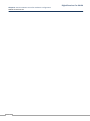
OVERVIEW ................................................................................................................................ 29
5.2
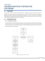
PROGRAM FLOW ....................................................................................................................... 29
5.2.1
5.2.2
5.2.3
5.2.4
5.2.5
5.2.6
5.3
5.3.1
5.3.2
5.4
Steering of Antenna .........................................................................................................................................29
Initialization of Antenna Position .....................................................................................................................30
Noise Diode ......................................................................................................................................................30
Saving Coordinates in a File .............................................................................................................................31
Loading coordinates From File .........................................................................................................................31
Graphical User Interface ..................................................................................................................................31
PROGRAM’S MAIN PARTS .......................................................................................................... 33
Interfacing With RIO ........................................................................................................................................33
Detecting feedback Pulses ...............................................................................................................................33
Outdoor Testing ........................................................................................................................ 34
CHAPTER 6 ___________________________________________________________ 35
CONCLUSION AND FUTURE WORK __________________________________________ 35
REFERENCES _________________________________________________________ 37
APPENDIX A __________________________________________________________ 39
ANTENNA MOTION CONTROLLER C++ CODE___________________________________ 39
APPENDIX B __________________________________________________________ 47
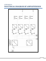
ELECTRICAL DIAGRAM OF AMPLIFIER BOX ___________________________________ 47
APPENDIX C __________________________________________________________ 49
INSTALLATION OF SOFTWARES ____________________________________________ 49
vi
LIST OF FIGURES AND TABLES
Figure 1-1: A typical block diagram of a hardware-based Radio-Astronomy-Receiver with Analog or Digital Correlator __ 2
Figure 1-2: A typical block diagram of a hardware-based Radio-Astronomy-Receiver with digital processing to calculate
Power Spectrum_____________________________________________________________________________________ 2
Figure 2-1: Block Diagram of the Existing System __________________________________________________________ 5
Figure 2-2: Existing SALSA Receiver (Q-Radio) Block Diagram ________________________________________________ 6
Table 2-1: Specification of the Existing System For Use in the Poject ___________________________________________ 7
Figure 2-3: Feed Horn Used Mounted Over the Antenna_____________________________________________________ 7
Figure 2-4: Top and Side View of the Feed Horn ___________________________________________________________ 8
Figure 2-5: Parabolic Reflector Antenna__________________________________________________________________ 8
Figure 2-6: Parabola Arc of the Reflector Antenna _________________________________________________________ 8
Table 2-2: Comparison Between Different SDR Platforms ___________________________________________________ 11
Figure 3-1: Functional Block Diagram of Software Receiver _________________________________________________ 14
Figure 3-2: Power Spectrum And Averaging Block _________________________________________________________ 15
Figure 3-3: Observation Block _________________________________________________________________________ 15
Figure 3-4: Conversion to Time-Domain Block ____________________________________________________________ 16
Figure 3-5: Software Receiver Snapshot _________________________________________________________________ 17
Figure 3-6: Block Diagram of Simulation ________________________________________________________________ 18
Figure 3-7: Test Setup _______________________________________________________________________________ 18
Figure 3-8: SIGNAL and REFERENCE Spectra Observed in Testing _____________________________________________ 19
Figure 3-9: Observation of Signal within Noise using (SIG-REF)/REF Technique __________________________________ 19
Figure 3-10: Testing in Outdoor Environment ____________________________________________________________ 21
Figure 3-11: Spectra of Hydrogen Line Taken From Existing System (in Units of Temperature) _____________________ 21
Figure 3-12: Spectra When Antenna is Misaligned FromThe Hydrogen Source __________________________________ 22
Figure 3-13: Spectra When Antenna is Aligned Towards Hydrogen Source _____________________________________ 22
Figure 4-1: Block diagram for antenna motion controller ___________________________________________________ 24
Figure 4-2: Rio 47200 _______________________________________________________________________________ 25
Figure 4-3: Amplifier Box (inside view) __________________________________________________________________ 25
Figure 4-4: Amplifier box (front view) ___________________________________________________________________ 26
Figure 4-5: Opto-couplers and the Wheel Providing Feedback of Antenna Position ______________________________ 26
Table 4-1: Physical Interfaces Connected to RIO __________________________________________________________ 27
Figure 5-1: Flow Graph of Antenna Steering _____________________________________________________________ 29
Figure 5-2: Flow Graph of Resetting Antenna ____________________________________________________________ 30
Figure 5-3: Flow Graph of Noise Diode __________________________________________________________________ 31
Figure 5-4: Flow Graph of Saving File ___________________________________________________________________ 31
Figure 5-5: Flow Graph of Loading File __________________________________________________________________ 31
Figure 5-6: The Main GUI of Antenna Motion Controller Software ____________________________________________ 32
Figure 5-7: GUI When Saving Coordinates to a .txt File _____________________________________________________ 32
Figure 5-8: GUI When Loading Coordinates From a .txt File _________________________________________________ 33
Figure 5-9: Figure Elaborating Detection of Feedback Pulses ________________________________________________ 34
Figure 5-10: Antenna Motion Controller software testing in real environment __________________________________ 34
vii
viii
CHAPTER 1
INTRODUCTION TO RADIO ASTRONOMY
RECEIVERS
1.1
TRANSMISSION AND RECEPTION
In typical scenario, Radio Frequency or RF signals are used to communicate information (Audio, Voice, Video,
Data etc) from one place to another. The Information signal is modulated on a RF carrier wave and
transmitted using antennas (wireless case) which convert electrical signals into electromagnetic waves that
can travel though a wireless medium. On the receiver side, the same frequency signal is received using the
antenna and fed to the receiver consisting of filters, amplifiers, down converters and demodulated to retrieve
the transmitted information. In radio astronomy, since there are no man-made transmissions, it is usually
required only to amplify very weak signals from sky and introduce some techniques to remove noise to get
some sort of profile (frequency, shape, bandwidth etc) of the incoming signal.
1.2
RADIO ASTRONOMY RECEIVERS
Radio astronomy is a subfield of astronomy that studies celestial objects at radio frequencies. The initial
detection of radio waves from an astronomical object was made in the 1930s, when Karl Jansky observed
radiation coming from the Milky Way. Subsequent observations have identified a number of different sources
of radio emission. These include stars and galaxies, as well as entirely new classes of objects, such as radio
galaxies, quasars, pulsars, and masers. The discovery of the cosmic microwave background radiation, which
provided compelling evidence for the Big Bang, was made through radio astronomy [1].
Radio astronomy is conducted using large radio antennae referred to as radio telescopes [1] that detect weak
signals from the sky. There are two types of receivers: direct detectors and heterodyne detectors. In
heterodyne detectors one or more mixer stages are involved to down-convert the incoming RF signal to
reduce processing overheads. After detecting a signal, its power spectrum is calculated using correlators or
FPGA based Fourier Transform receivers and is used to further process the signal in order to read and get
information about source of emission. These types of receivers are usually termed as spectrometers.
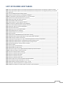
Figure 1-1 and 1-2 show typical and simplified low frequency (lower than 100 GHz) Radio-Astronomy-Receiver
(RAR) or Spectrometer. For higher frequencies and for more sensitive receivers with ultimate performance
the first stage of LNA is not present [2]. As shown on figure 1-1, a correlator calculates the power spectrum
based on Wiener-Khinchin-Theorem which states that the power spectrum of a signal is the Fourier transform
of its autocorrelation function (ACF). The correlator might be analog or digital. For a digital correlator, the
signal is first digitized using analog-digital converter (ADC). Figure 1-2, shows a digital receiver, which
incorporates an A/D down-conversion. This type of receiver is built using modern high speed ADCs and
powerful FPGAs. This works on the principle that the magnitude square of the Fourier transform is the power
spectrum.
1
Digital Receiver For SALSA
Chapter 1: Introduction to Radio Astronomy Receivers
Umair Naeem
Figure 1-1: A typical block diagram of a hardware-based Radio-Astronomy-Receiver with analog or digital Correlator
Figure 1-2: A typical block diagram of a hardware-based Radio-Astronomy-Receiver with digital processing to calculate Power
Spectrum
The existing SALSA receiver is based on what is shown in figure 1-1. Figure 1-2 shows the system that is
implemented in software and will be discussed in detail.
After being received from antenna (typically parabolic reflector), the incoming signal is amplified by a high
gain Low Noise Amplifier (LNA) which is down converted to Intermediate Frequency (IF) using mixers in order
to facilitate further processing. Then, the Analog-to-Digital conversion takes place so that the signal can be
digitally processed in modern receivers. A Digital-Down-converter down converts the IF signals into baseband
for processing by dedicated or general purpose (PC) processors. The output can be in the form of display
showing some spectra and/or data files.
2
1.3
OBSERVING TECHNIQUES
There are different observation techniques to observe weak signals from the sky. These are defined below.
Frequency-Switching, in which the spectrum at exactly the frequency of interest is
observed/calculated first for a certain period of time and stored. Then the local oscillator frequency of
the mixer is changed to a few MHz away from frequency of interest and then the spectrum is
calculated at that frequency. The spectrum at exact frequency of interest is termed Signal and the
spectrum at some offset frequency is termed Reference.
Position-Switching, in which first for a few moments the spectrum at exactly the frequency of interest
and exactly at the right position on the sky is observed/calculated and stored. Then the direction of
the antenna is changed only to some other position from where there is no emission at the frequency
of interest and then the spectrum is calculated at the same frequency of interest. The spectrum at
exact frequency of interest observed from the exact position of interest is termed Signal and the
spectrum observed from offset position is termed Reference.
A signal processing technique is employed to make the weak signal at frequency of interest further
detectable within the noise which in mathematical form is
1.4
THESIS MOTIVATION
The usual approach (hardware-based) to detect signals has some limitations like to adapt to new services and
standards. Each element in the receiver usually works for a particular specification and needs to be changed
or re-designed or re-purchased if there is some change in the receivers’ pecifications (Frequency, Gain,
Bandwidth, Weight etc). This increases the hardware cost and is time-consuming (design, purchase and
installation). Software-Defined-Radio (SDR), as described later, can do almost all of the said processing using
software running on PCs with a general-purpose single-piece device. Re-designing the software is time and
cost effective. Considering figure 1-2, the section in dotted lines (a digital acquisition device) is usually
integrated into a single device (USRP2 in our case) with configurable parameters and all the remaining signal
processing is done in software which gives more flexibility over the entire-hardware-based approach.
The second part of the project deals with steering of the antenna, saving and loading antenna position in
some file (Antenna Motion Controller Software). In the existing system, the control of antenna is divided into
two parts; the C program and Q-radio (microcontroller based hardware). With the upgrade, the antenna is
completely controlled by a single C program. This program is flexible enough to easily change the number of
pulses per degree, position of the closed switches both in azimuth and elevation directions, initial position of
antenna etc. Also if one wants to reconfigure the interface between antenna and the C program for future
extensions, one would just need to change some parameters in the program (clearly commented). The
antenna motion controller software is flexible enough to be used with different antenna mounts due to the
use fast sampling to read feedback pulses from antenna.
1.5
THESIS ORGANISATION
3
Digital Receiver For SALSA
Chapter 1: Introduction to Radio Astronomy Receivers
Umair Naeem
The report comprises of two parts, Antenna Steering and Control Software and a Software-based Digital
Receiver. These two tasks were completed by Nabeel Ahmed Durrani and Umair Naeem respectively and
their reporting is organized as follows,
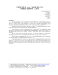
Chapter 2 gives an overview of the existing system and currently available Software-Defined-Radio (SDR)
architectures. Chapter 3 covers the design analysis done for the receiver using GNU Radio and future
possibilities and extension in the system. Chapter 4 covers hardware configuration, physical interfaces
connected to different hardware and characteristics of hardware components used in this project. Chapter 5
deals with different aspects of the antenna motion controller software. Chapter 6 includes conclusions and
suggests future work of this thesis.
4
CHAPTER 2
OVERVIEW OF EXISTING SYSTEM AND SOME
OF THE SOFTWARE-DEFINED-RADIO (SDR)
ARCHITECTURES
2.1
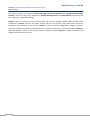
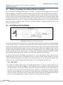
OVERVIEW OF THE EXISTING SYSTEM
Figure 2-1: Block Diagram of the Existing System
Figure 2-1 shows the existing system used for the observation of the hydrogen line. After the amplification in
the LNA the signal is carried by coaxial cable to a preamplifier box where it is further amplified and filtered in
a narrow bandwidth filter to remove interference signals around the 1420MHz line. The receiver box (named
Q-Radio) accommodates the down-conversion circuitry, the driving IC's for the antenna motors, the
correlator and a micro-controller which controls all functions and communicates with a PC.
In the receiver box, the signal from the preamplifier box is further amplified and then down-converted to an
Intermediate Frequency (IF) and a total bandwidth of 2,4 MHz using Side Band Separation technique. The
microcontroller performs auto-correlation of the signal with a resolution of 12,5 kHz and also gives the
possibility to integrate over a certain period of time. This pattern is sent to the PC via serial port. A Linux
based software calculates the frequency spectrum and logs the data. The user enters the azimuth and
elevation coordinates for the observation in the software and then the computer communicates with the
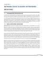
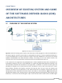
microprocessor which commands the mount motors and reads its current position. Figure 2-2 shows the
detailed block diagram of the existing receiver in Onsala Space Observatory developed by Rune Byström (Åre
Elektronik). It can be seen that the RF signal is split in two branches and are mixed with a sinusoidal signal
5
Digital Receiver For SALSA
Chapter 2: Overview Of Existing System And Some of the SDR Architectures
Umair Naeem
from a local oscillator with a frequency of about 1418 MHz which are phase shifted with 90 degrees. After
mixing, both signals are digitized and then added together after introducing additional 90 degrees phase shift
in the corresponding channel to cancel the unwanted side band.
Figure 2-2: Existing SALSA Receiver (Q-Radio) Block Diagram [3]
6
Digital Receiver For SALSA
Chapter 2: Overview Of Existing System And Some of the SDR Architectures
Umair Naeem
One of the main objectives for this thesis is to replace the correlator with a general purpose digital front-end
device named USRP2 from Ettus Research and implement a new software for data analysis based on GNU
radio. The hardware specifications of the existing system available for the project, are summarize in the table
below.
Table 2-1: Specification of the existing system for use in the project
Components
Specification
2.3m Antenna
LNA
Amplifier/Filter
Feed Horn
F/D : 0.4
Gain: 28 dB, NF: 0.34 dB, 1420 MHz
Range: 1000-2000 MHz, Gain: 24 dB
Inner Dia: 15.5 cm/0.733 , 1420 MHz
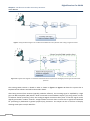
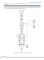
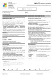
2.1.1 Feed horn
Figure 2-3: Feed horn used mounted over the antenna
The feed horn is a corrugated aperture-controlled horn in which the phase variation over the aperture is
small. By referring the design graph in [4, page 339], the directivity was calculated to be about 6 dB.
7
Digital Receiver For SALSA
Chapter 2: Overview Of Existing System And Some of the SDR Architectures
Umair Naeem
Figure 2-4: Top and Side View of the Feed Horn
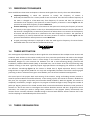
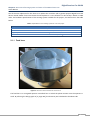
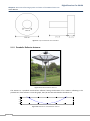
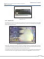
2.1.2 Parabolic Reflector Antenna
Figure 2-5: Parabolic Reflector Antenna
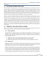
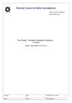
The Antenna is a parabolic mesh-surface reflector having the diameter of 2.3 meters. Following is the
parabola arc of the reflector. From this graph, the F/D ratio was calculated to be about 0.4.
0
-100
-200
-300
-400
-1500
-1000
-500
0
500
Figure 2-6: Parabola Arc of the Reflector Antenna
8
1000
1500
Digital Receiver For SALSA
Chapter 2: Overview Of Existing System And Some of the SDR Architectures
Umair Naeem
2.2
SOFTWARE-DEFINED-RADIO (SDR)
A software-defined radio (SDR) system is a hardware-cum-software-based radio communication system
which can tune to any frequency band and decode different modulations/encoding schemes across a large
frequency spectrum by means of a programmable hardware, which is controlled by software. An SDR
performs significant amounts of digital signal processing in a general purpose computer (PC), or a
reconfigurable piece of digital electronics [5]. SDR has evolved with advancement in computing machines and
high-speed analog-digital (A/D) and digital-analog (D/A) converters. Thus SDR allows a single device to
support a wide range of capabilities previously available only through multiple products.
Usually it is required that signals received by an antenna should be digitized so that SDR may use these
digitized samples at RF frequencies (around GHz frequencies) to perform further signal processing steps (IF
conversion, filtering, baseband conversion etc). But due to certain limitations like unavailability of A/D
converters at very high frequencies (starting from a few GHz) and very high speed general purpose
computers, digitization takes place after the IF or baseband demodulator stage. That typically means that
hardware is still required to convert the signals of interest into and out of the “baseband” frequencies in the
digital domain, but all of the complex processing performed at baseband is handled in the digital software
domain [6]. Yet, such hardware is usually fairly simple comprising of a local oscillator and mixer, and a pair of
low-pass filters.
2.3
REVIEW OF AVAILABLE SDR PLATFORMS
There are many platforms or architectures available to perform signal processing together with software
domain. A brief introduction to some of the devices that use SDR is given below:
2.3.1 NI PXIe-5641R [7]
The NI PXIe-5641R uses LABView software to develop signal processing algorithms and applications. The NI
PXIe-5641R is an intermediate frequency (IF) transceiver for applications such as radio-frequency
identification (RFID) tests, spectral monitoring, real-time spectrum analysis, RF dynamic test, and softwaredefined radio (SDR). It features:
100 MS/s A/D converters with 20 MHz bandwidth digital down-converters (DDCs).
200 MS/s D/A converters with 20 MHz bandwidth digital up-converters (DUCs).
Radio frequency (RF) applications at frequencies up to 2.7 GHz with bandwidths up to 20 MHz.
2.3.2 WinRadio [1]
WiNRADiO is the name of a manufacturer of radio communication equipment as well as a brand name of
applied software radio receivers, antennas and accessories. Applications of WiNRADiO receivers include
general purpose radio, radio astronomy, or SETI (Search for Extraterrestrial Intelligence).
WinRadio has developed its own receivers (G303 etc) with software to digitize the signal coming from
antenna and process it in software domain. This includes tuning the receiver, controlling the attenuator
and gain, as well as reading the signal strength. To complete a third-party software-defined receiver based
on hardware platform, all that is needed is DSP software (running on the PC), to filter and demodulate the
low IF (12 kHz) signal made available by the receiver. This 12 kHz IF signal is available at the output of the
9
Digital Receiver For SALSA
Chapter 2: Overview Of Existing System And Some of the SDR Architectures
Umair Naeem
receiver, and is usually externally connected to the line input of the sound card. For standard USBconnected G303e receivers, the IF signal is available via the USB interface.
2.3.3 Vanu [8]
Vanu is a software radio that is primarily used for mobile communication. It utilizes a software radio base
station to form software RAN (Radio Access Network) solutions. Vanu also developed MultiRAN to
support multiple virtual base stations (vBTS) running on a single BTS hardware platform. Different
resources like antennas, BTS electronics, and backhaul can all be shared. MultiRAN allows multiple
operators to virtually share a single physical network. This allows operators to experience the cost benefit
of shared infrastructure without the cost, complexity and risk associated with traditional network sharing
arrangements.
2.3.4 Pentek Model 7142-428 [9]
Digital transceiver with digital down converter and interpolation filter is a complete software radio system
in a PMC/XMC module with a decimation range from 2 to 65,536 and interpolation range from 2 to 32,768.
It includes four A/D and one D/A converters with bandwidths up to 40 MHz and above for connection to
HF or IF ports of a communications or radar system.
2.3.5 USRP and GnuRadio
GnuRadio (http://www.gnu.org/software/gnuradio) provides a comprehensive toolkit for the
experimentalist in SDR to produce applications in a variety of disciplines. The work originated at MIT,
with Eric Blossom shepherding its emergence as a GPL-licensed toolkit that is seeing significant usage by
RF experimenters and engineering students worldwide [6].
The GnuRadio project resulted in the Universal Software Radio Peripheral (USRP) which is a digital
acquisition (DAQ) system containing four 64 MS/s, 12-bit A/D converters (ADCs), four 128 MS/s, 14-bit
D/A converters (DACs), and supports USB 2.0 interface. The USRP is capable of processing signals with 16
MHz of bandwidth.
The USRP takes daughter-cards to map the frequency ranges of interest into the “baseband” that is visible
by the A/D hardware. Several different daughter-cards are available, but the cards of most interest to
amateur radio astronomy enthusiasts would be [6]:
●
DBS_RX - RX only, covers 850-2250 MHz
● TV_RX – RX only, covers 50-800Mhz
The DBS_RX converts the incoming RF into complex signals in a direct-conversion approach (with the
signals extending from DC up to the low-pass cut-off of the receive converter) [6].
The TV_RX converts the incoming signal into a 5.75MHz IF. The desired frequency and bandwidth are
settable using the GnuRadio toolkit and GUI [6].
The USRP was developed by Matt Ettus [1]. Later on the USRP2 was built on the success of the original
USRP, and added new features [10] like Gigabit Ethernet, 25 MHz bandwidth etc.
10
Digital Receiver For SALSA
Chapter 2: Overview Of Existing System And Some of the SDR Architectures
Umair Naeem
GnuRadio is an open-source SDR toolkit which contains a library of signal processing blocks (like in
Simulink/Matlab) which are interconnected like a flow graph. Each signal processing block is written in
C++. The processing blocks in GnuRadio are arranged or organised with a Python-based applications
framework. The Python code manages interconnection of processing blocks, and also provides userinterface functions. Table 2-2 shows the comparison between different SDR platforms.
Table 2-2: Comparison between different SDR platforms
NI PXIe-5641R
2 IF inputs and
2 IF outputs
20 MHz realtime IF
bandwidth
Xilinx Virtex-5
SX95T FPGA
optimized for
DSP
100 MS/s 14-bit
ADC
200 MS/s 14-bit
DAC
Built-in digital
upconverters
and
downconverter
s
>76 dB input
SNR
250 kHz to 80
MHz IF center
frequency
-143 dBm/Hz
input noise
density
2.4
WinRadio
IF of 12 kHz
USB interface
Extraordinary
sensitivity
Real-time
spectrum
analyzer
Spot-on tuning
in 1Hz steps
Accurate signal
strength
indicator
Very low phase
noise
DRM decoder
option
Continuously
variable IF
bandwidth 1Hz
- 15kHz
User adjustable
filter selectivity
Built-in test and
measurement
instrumentatio
n
Interactive
block diagrams
Vanu
Frequency: 850 MHz,
1800 MHz, 1900 MHz
Output Power: 20W per
carrier
Backhaul: IP over
Ethernet or E1/T1
Interfaces: Antenna ports
(50 ohm N female), GSM
– BTS to BSC (GSM A-bis
over IP),
CDMA – BTS to BSC
(CDMA A-bis over IP)
Supported Standards:
GSM/GPRS/Edge/CDMA2
000 1xRTT
Sensitivity: GSM (-112
dBm), CDMA (-126 dBm)
Capacity: GSM (upto 48
carriers), CDMA (upto 24
carriers)
Pentek Model
7142-428
Full scale input:
10 dBm into 50
ohms
3 dB passband:
250 kHz to 300
MHz
ADC: Sampling
rate (1 MHz to
125 MHz)
Resolution: 14
bits
Decimation: 1
to 4096
Input B/W: 40
MHz
Upconverte
Sample Rate:
500 MHz max.
and resolution
16 bits
Interface: PCI
Bus (64-bit, 66
MHz), DMA: 9
channel
demand-mode
and chaining
controller
USRP2 and
GNURadio
Gigabit
Ethernet
interface
25 MHz of RF
bandwidth
Xilinx Spartan 32000 FPGA
Dual 100 MHz
14-bit ADCs
Dual 400 MHz
16-bit DACs
1 MByte of
high-speed
SRAM
Locking to an
external 10
MHz reference
1 PPS input
Configuration
stored on
standard SD
cards
The ability to
lock multiple
systems
together for
MIMO
CHOICE OF SDR PLATFORM
Comparing the different SDR platforms available, GnuRadio with USRP2 was chosen in this thesis to develop
SDR for the astronomical spectrometer for the detection of Hydrogen line at 1420 MHz. For this purpose,
DBS_RX daughterboard is used to get RF and convert it to IF and baseband for further processing. USRP2 and
Gnuradio were chosen for the following reasons,
Input signal frequency from 800 MHz to 2.4 GHz
Largest Single Sided bandwidth of 25 MHz
Open-Source (Cost-effective and expandable) solution
11
Digital Receiver For SALSA
Chapter 2: Overview Of Existing System And Some of the SDR Architectures
Umair Naeem
12
CHAPTER 3
DESIGN FOR THE SOFTWARE RECEIVER
USING GNURADIO
3.1
INTRODUCTION
Keeping in mind the main goals of the project, the whole existing correlator receiver was converted into
software receiver using the GnuRadio software platform. The USRP2 serves as an RF front end to get the
digital signals for GnuRadio.
3.2
DESIGN ANALYSIS
The signal flow in the existing receiving system was as follows,
The RF signal coming from the antenna, amplified through the LNA (and pre-amplified as necessary),
is fed into an IF stage which converts RF into IF.
This IF is used to calculate the frequency content of the signal hence the power spectrum is calculated
in the correlator and fed into an accumulator to integrate several spectra for averaging purpose. This
averaging ensures the removal of as much random noise as possible.
The observations were done using frequency-switching. The spectrum at exactly the Hydrogen line
(1420MHz) is calculated and stored for a certain period of time. Then the local oscillator frequency of
the mixer (IF stage) is changed to a few MHz away from Hydrogen line and then spectrum is
calculated at that frequency. The Spectrum at exact the Hydrogen line is termed Signal and spectrum
at some offset frequency from Hydrogen line is termed Reference.
A signal processing technique is employed to make the weak Hydrogen line signal further detectable
within the noise which in mathematical form is
3.3
IMPLEMENTATION IN GNURADIO AND USRP2
According to the above methodology for the receiver, the digital software receiver was implemented in the
chosen SDR architecture as follows,
The RF signal coming from Antenna, amplified through LNA (and pre-amplified as necessary), is fed
into USRP2 which has a DBS_RX daughter board that contains an IF stage for converting RF into IF and
then baseband with a maximum bandwidth of 50 MHz. This baseband signal is available through
Ethernet interface to GnuRadio running on a PC for further processing. GnuRadio makes use of
software filters and FFT to calculate and display the power spectrum.
There is some limitation in GnuRadio. It works well in real-time, not in store-and-process method. In
order to have two slightly different frequency signals (Signal and Reference), frequency switching is
not used. Instead, the whole band consisting of the signal as well as the reference was obtained for
processing. In our case this was as follows
Signal at 1420.4 MHz with 2.5 MHz bandwidth (1419.15 – 1421.65) MHz.
13
Digital Receiver For SALSA
Chapter 3: Design For The Software Receiver Using GnuRadio
Umair Naeem
Reference at 1417.9 MHz with 2.5 MHz bandwidth (1416.65 – 1419.15) MHz.
Total bandwidth comprising of Signal and Reference thus became 5 MHz.
The signal and reference signals are then filtered through separate filters, their FFT is calculated,
averaged and finally the above mathematical equation is applied to detect the required signal.
Figure 3-1 Functional block diagram of the developed software receiver.
Figure 3-1: Functional Block Diagram of Software Receiver
14
Digital Receiver For SALSA
Chapter 3: Design For The Software Receiver Using GnuRadio
Umair Naeem
3.3.1 USRP2 Source
This source block defines the parameters to get signals from USRP2. “Source” refers to the signal flow
starting from USRP2 as seen from the GnuRadio point of view. Parameters are defined below,
Frequency: This is the frequency which will be down-converted to 0 Hz (baseband). It was set to the center
of Reference frequency band i.e. 1417.9 MHz.
Decimation: This parameter sets the decimation that USRP2 should perform. Normally since the USRP2
provides a bandwidth of 50 MHz it means that the sample rate of the output signal from USRP2 is at 100
Msamples/sec (twice of bandwidth according to Nyquist Theorem). We require 5 MHz of bandwidth so we
need 10 Msamples/sec of sample rate. Therefore decimation should be 100/10 = 10.
3.3.2 FFT Filters
There are two FFT filters to filter out Reference and Signal. The FT filter performs filtering in frequency
domain which is faster than time domain filtering.
3.3.3 Power Spectrum and Averaging
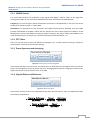
Figure 3-2: Power Spectrum and Averaging Block
These blocks calculate the Fast-Fourier-Transforms (FFT) of both Reference and Signal and then take the
square of the magnitude to get the power spectrum. Averaging filters perform averaging to smoothen the
signals and remove as much random noise as possible.
3.3.4 (Signal-Reference)/Reference
Figure 3-3: Observation Block
These blocks actually perform the mathematical operation described above. They are implemented with
the following simplification,
15
Digital Receiver For SALSA
Chapter 3: Design For The Software Receiver Using GnuRadio
Umair Naeem
3.3.5 Conversion to Time Domain and FFT Scope
Figure 3-4: Conversion to Time-Domain Block
This block converts the frequency domain signal back into time domain. For this, it takes the inverse FFT,
since we need to display the power spectrum of (Sig - Ref)/Ref and the FFT scope does this on time domain
signal. The FFT Scope also provides with additional averaging options to smoothen the signal as much as
required.
The complex conjugate block takes the complex conjugate of the incoming time domain signal. This is to
invert (flip) the spectra. The previous blocks actually process the signals and the resultant signals’ spectra
is flipped to negative side of the frequency scale. In order to re-flip it to positive side of the frequency
scale, this block is added here.
3.3.6 File Save
This sink block is used to store the time domain signal in binary file format. This file can be read by a File
Source block.
Following figure shows the software receiver made in a tool (named GnuRadio Companion or GRC) of
GnuRadio which provides graphical user interface to design systems.
16
Digital Receiver For SALSA
Chapter 3: Design For The Software Receiver Using GnuRadio
Umair Naeem
Figure 3-5: Software Receiver Snapshot
3.4
LAB VERIFICATION
Before testing the receiver in real environment, a setup was made to test the software receiver for eventually
debugging the software, checking each of the receiver blocks and investigating the sensitivity issues since it
would be a cumbersome job to setup the PC with all the wiring connections in real outdoor environment
directly. The purpose of this setup was to test the USRP2 for its sensitivity to weak signals and to check
whether a weak signal hidden in the noise is detectable by the software receiver or not. The USRP2 was seen
to have a sensitivity of around -60 dBm which means it cannot detect signals below this level. For detecting
lower level signals (that would be the case for astronomical objects) we need pre-amplifiers and set some gain
of USRP2 device as well to amplify the incoming signal as much as it can be seen by the receiver (to have the
signal greater than -60 dBm).
17
Digital Receiver For SALSA
Chapter 3: Design For The Software Receiver Using GnuRadio
Umair Naeem
Figure 3-6: Block Diagram of Simulation
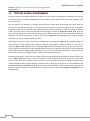
Figures 3-6 and 3-7 show the block diagram and the photograph respectively, of the setup in which a noise
diode (10,000o K). In addition a test signal at 1420.4 MHz was injected through pre-amplifier(s) to have a total
gain of around 70 dB including the USRP2 gain. The noise floor showed up above the -60 dBm which means
that the incoming signal has been provided sufficient with gain to cross the -60 dBm sensitivity limit and is
detectable. The weak test signal (around -125dBm) was not detectable from within the noise diode’s noise as
it has very low level (see figure 3-8). To detect this test signal the (sig-ref)/ref method (see figure 3-9) was
performed and the test signal appeared, verifying that the new system is now ready to test for Astronomical
sources.
Figure 3-7: Test Setup
18
Digital Receiver For SALSA
Chapter 3: Design For The Software Receiver Using GnuRadio
Umair Naeem
Figure 3-8: SIGNAL and REFERENCE Spectra Observed in Testing
Figure 3-9: Observation of Signal within Noise using (SIG-REF)/REF Technique
19
Digital Receiver For SALSA
Chapter 3: Design For The Software Receiver Using GnuRadio
Umair Naeem
3.5
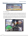
TESTING IN REAL ENVIRONMENT
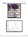
The whole setup was assembled outdoor in order to test the system for Hydrogen line detection. This testing
in real environment would be validating that all the components are placed in the right order. (antenna, LNA,
power supply etc).
First the antenna was pointed in a random direction and the power level of the signal was noted. Then the
antenna was pointed towards the sun and power spectrum lifted a little showing that all the connections
were fine and that the pre-amplifier and software receiver is working properly in accordance with the lab test
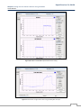
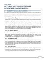
results. Then the antenna was pointed towards the hydrogen line source. Figures 3-10, 3-12, 3-13 show the
setup and the difference in the spectrum of (sig-ref/ref) without and with the antenna pointed towards the
Hydrogen line source respectively. It can be seen from the figures 3-12 and 3-13 that the receiver worked
properly as the signal is differentiable from noise.
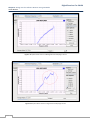
Comparing the spectrum taken with the old configuration of SALSA ([11], figure 3-11) pointed toward the
same direction of the galactic plane (Galactic longitude l=120 degrees, Galactic latitude b = 0) and the
spectrum (figure 3-13), obtained with the upgraded digital software receiver pointing in the same direction,
clearly shows the functionality of the upgraded digital receiver. The difference is spectrum can be explained
by the approximate pointing during our experiment, but it certainly looks like a detection! It would also have
been useful to observe in a slightly larger or shifted (towards right) band [11].
The observed spectrum range seems far wider than the actual spectrum band needed to observe (within red
circle in figure 3-13). This is due to the FFT Scope block of the GnuRadio, where no zooming on a particular
section of the spectrum is possible; hence we have to see the whole band which is being translated from
analog to digital domain through sampling. To observe only a small part of spectrum, one could decimate the
(SIGNAL-REFERENCE)/REFERENCE signal to a point where the bandwidth is half the decimated sampling rate
(Nyquist Theorem). Actually, a small decimation is performed here if we compare figures 3-13 and 3-9 to see
the difference.
20
Digital Receiver For SALSA
Chapter 3: Design For The Software Receiver Using GnuRadio
Umair Naeem
Figure 3-10: Testing in Outdoor Environment
Figure 3-11: Spectra of Hydrogen Line Taken From Existing System (in Units of Temperature)
21
Digital Receiver For SALSA
Chapter 3: Design For The Software Receiver Using GnuRadio
Umair Naeem
Figure 3-12: Spectra When Antenna is Misaligned towards Hydrogen Source
Figure 3-13: Spectra When Antenna is aligned from the Hydrogen Source
22
CHAPTER 4
ANTENNA MOTION CONTROLLER
HARDWARE CONFIGURATION
4.1
REVIEW OF THE AVAILABLE HARDWARE
In our application, there were many options for choosing hardware for controlling the motors and reading the
feedback encoders. Different vendors provide such hardware with different features. This section describes
some of the available hardware and motivates our choice of Galil RIO 47200 because of its advantages over
other available hardware.
4.1.1 Rabbit op 7210 eDisplay
Rabbit provides op 7210 eDisplay Ethernet/intelligent operator interface. It provides 16 digital inputs and 8
digital outputs. Digital outputs are individually configurable in software for different current and voltage
outputs. Current and voltage can be set up to 350mA and 36VDC respectively. It provides Ethernet as well
as two RS-232 or one RS-232 (with CTS/RTS) interfaces. Programs are developed for the op 7210 using
Rabbit’s industry-proven Dynamic C software development system. This development system offers almost
all the capabilities like pop-up menus, onscreen keypads, data transmission/reception over TCP/IP and
serial connections, analog volt meter display, and many more [12]. The main disadvantage of op 7210 is its
number of digital outputs; it has only 8 digital outputs. This project utilizes 5 digital outputs, but such a
short number of digital outputs will limit the possibility of future expandability.
4.1.2 Trio Motion CAN 16-I/O
The CAN 16-I/O module from Trio Motion Technologies allows the 24volt digital inputs and outputs of the
Motion Coordinator to be extended in blocks of 16 bi-directional channels. It provides its own made
Motion Perfect software for programming and analyzing I/O status. However, this module does not
provide the flexibility to be used with most widely used languages like MATLAB, C++ etc. It supports G
code, which is one of the standard languages that is widely used in CNC machines [13].
4.1.3 NI compactRIO Series
National Instruments provide a series of compactRIO components. These series provide the control to a
variety of hardware types with the integration of the very popular LabView software. The main drawback
in NI compactRIO series is that it only supports single axis devices while the antenna mount used in this
project utilizes two axes motion. Using these compactRIO just increases un-necessary components and so
the cost will also increase [14].
4.1.4 Galil’s DMC family
Galil’s DMC family is also a strong candidate for our application. The DMCs are specialized motion
controlling boards. They have 32 bit processor and provide standard PCI and ISA slots for communication.
They also provide different modes of motion like point to point positioning, jogging etc [15].
23
Digital Receiver For SALSA
Chapter 4: Antenna Motion Controller Hardware Configuration
Nabeel Ahmed Durrani
4.2
Choice of hardware for Antenna Motion Controller
The main reason for choosing the RIO family is its simplicity. It provides number of digital outputs which are
perfectly matching our application in which we have to give commands to the azimuth and elevation motors.
It also has digital inputs which makes easy to read feedback encoders to get azimuth and elevation pulses
from the motor. It also provides standard 100Base-T Ethernet and RS-232 options to interface with PC. Galil
provides its own made C++ communication library which makes it really easy to communicate with RIO and
interrogating about its I/O status. It provides on board programming which can be a very important feature
when using RIO as standalone motion controller. It provides flexibility to add more RIO units with it via
Ethernet or RS232 port [16].
4.3
SYSTEM BLOCK DIAGRAM
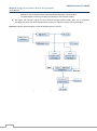
Figure 4-1: Block diagram for antenna motion controller
One of the main goals of this master thesis is to minimize the hardware used in the previous system (Q-radio).
In the previous system, a C program just provides GUI to the controller (Q-radio). The C program, which
controls Q-radio, sends commands in string format to the Q-radio, in which a microcontroller decodes these
commands and send appropriate signal to antenna motors. Then Q-radio reads feedback pulses from the
antenna feedback mechanism and sends the number of feedback pulses to the C program (again in string
format). The main idea of this master thesis is to replace this complicated hardware by simplified software
and to minimize the hardware needs; therefore the system block diagram is very simplified.
The mount of the antenna is provided by Alfa Radio Ltd. It’s a heavy duty antenna rotator. Each axis uses a
double worm gear drive system. Two windshield motors are used as drivers. Motors operate on ±12-24V,
2,5A, with peak starting current of 4A. Motors have two limit switches in each axis. One limit switch is at a
complete rotation in azimuth (360 degree) and the other is on 95-100 degrees in elevation [17].
4.3.1 Rio 47200
Rio 47200 has multiple digital inputs and multiple digital outputs. As shown in block diagram, Rio is
connected to the PC via Ethernet 100Base-T, which takes care of the communication part between the PC
and the Rio board. Two wires for azimuth control and two wires of elevation control of the motor are
connected to the digital outputs of the RIO and these outputs are controlled by the Antenna Motion
Controller software (defined in next chapter). To control the rotation of the antenna, there are feedback
pulses for azimuth and elevation from the motors which rotate the antenna. These feedback pulses wires
are connected to the digital input of the Rio, as these are TTL pulses of 8-12Hz frequency.
24
Digital Receiver For SALSA
Chapter 4: Antenna Motion Controller Hardware Configuration
Nabeel Ahmed Durrani
Figure 4-2: Rio 47200
4.3.2 Amplifier Box
The output from the Rio are TTL levels, but the motors which rotate the antenna requires at least ±18V
with a continuous current of ±2.5A and a ±4A peak current, so there is an considerable need of amplifier
between Rio and antenna motor.
Figure 4-3: Amplifier Box (inside view)
Furthermore, the direction of steering is changed by changing the polarity of the power supply, and this is
accomplished by creating a control signal with the power supply, which when enabled, delivers power with
positive polarity and when disabled, delivers power with negative polarity.
The amplifier front panel contains discrete input connection from Rio to the amplifier and amplified output
azimuth and elevation control signals (marked by solid black boxes in figure 4-4) to the antenna motors.
25
Digital Receiver For SALSA
Chapter 4: Antenna Motion Controller Hardware Configuration
Nabeel Ahmed Durrani
Figure 4-4: Amplifier box (front view)
4.3.3 Antenna Motor
The antenna motors which rotate the antenna have a feedback mechanism, which is fairly simple. A 12 leg
wheel (as shown in figure 4-5) is mounted on a shaft in one of the gearboxes of antenna motor, so
whenever the antenna moves, it also rotates this wheel. There is an opto-couple behind this wheel, so that
TTL pulses are created when light from the opto-couple falls on it. These are TTL pulses and have
frequency ranges from 8 to 12Hz. One degree rotation in azimuth or elevation generates 4 feedback
pulses, which gives an angular accuracy of 0.25 degree (the full moon has an angular diameter of about
half a degree [18]). The angular resolution of the 2.3m SALSA antenna is about 7◦ at the frequency of the
HI line, 1420 MHz [18]. These pulses directly go to the digital input of the Rio which is then read by the
antenna motion controller software.
Figure 4-5: Opto-couplers and the Wheel Providing Feedback of Antenna Position
26
Digital Receiver For SALSA
Chapter 4: Antenna Motion Controller Hardware Configuration
Nabeel Ahmed Durrani
4.4
CONFIGURATION OF RIO
The following table contains physical interfaces which are connected to Rio. A small description of every
interface is also given in the table below.
Table 4-1: Physical Interfaces Connected to RIO
Wire
colour/number
Red
Black
Blue
Pink
Brown
Yellow
Gray
White
Wire # 1
Wire # 2
Wire # 3
Wire # 4
Noise diode
Connected to
RET
AGND
Op0A
Op0B
DO5
DO6
DO7
DO8
INC1B
DI9
INC1A
DI8
D02
Description
+18-36V Power Supply
Ground for Power Supply
+12-24V Output Power Supply for DO[0-7]
Output Power GROUND for DO[0-7]
Direction signal for azimuth
Motion signal for azimuth
Direction signal for elevation
Motion signal for elevation
To enable IN jumpers
Elevation feedback
Input common DI[8-15]
Azimuth feedback
Noise diode control
Rio has two power options; external power supply and PoE (Power over Ethernet). When external power
supply is used then four jumpers are placed at pins labelled as AUX on Rio (default setting) and when
power over Ethernet is required then instead of placing 4 jumpers on AUX, 4 jumpers are placed at pins
labelled as PoE on Rio.
The INC jumpers can be used when an external power supply is not desired for digital inputs 0-15. These
inputs can use the internal +5V from the RIO instead. To do this, place a jumper on the pins labelled INC
[16].
27
Digital Receiver For SALSA
Chapter 4: Antenna Motion Controller Hardware Configuration
Nabeel Ahmed Durrani
28
CHAPTER 5
ANTENNA MOTION CONTROLLER
SOFTWARE
5.1
OVERVIEW
Antenna motion controller software is developed using C++ language and used for steering of the antenna in
azimuth and elevation directions, resetting the antenna to the north and zenith positions, enabling and
disabling noise diode, saving azimuth and elevation coordinates in a .txt file. The User can also load the
coordinates from a saved file. The GUI (Graphical User Interface) is built mainly by means of the C++ Qt library
which is specially developed for graphics in C++ language.
5.2
PROGRAM FLOW
5.2.1 Steering of Antenna
The antenna motion controller software enables the user to steer antenna in both azimuth and elevation
directions from GUI. The user can give azimuth values form 0-360 degrees and elevation values from 0-90
degree in double spin box created using Qt library. The flow graph of the program to steer the antenna in
desired directions is presented below.
Figure 5-1: Flow Graph of Antenna Steering
29
Digital Receiver For SALSA
Chapter 5: Antenna Motion Controller Software
Nabeel Ahmed Durrani
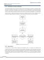
5.2.2 Initialization of Antenna Position
The software enables the user to the reset antenna to the north direction in azimuth (i-e 0 degree) and to
the zenith in elevation (i-e 90 degree). The antenna has its close switches both in horizontal and vertical
directions. The antenna is mounted so that it has its horizontal close switch at North and vertical close
switch at zenith direction. Indeed the vertical close switch is not exactly at 90 degree, it is around at 95
degree elevation, so when performing the reset function, software moves the antenna 5 degrees from its
close switch to get the actual zenith position. The flow graph of reset function, is presented below.
Figure 5-2: Flow Graph of Resetting Antenna
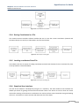
5.2.3 Noise Diode
A noise diode is a device used to simulate the atmospheric noise. It is turned on for calibration and
simulation purposes. The control signal of the noise diode is connected to one of the outputs of the Rio
board, and it can be turned on or off just by sending 0 or 1 at this output. A Boolean variable is declared for
the noise diode, whenever the GUI sends this Boolean variable as true, a 1 is sent to the output of the RIO
and the noise diode is turned on, and when it is false, a 0 is sent to the output of RIO and noise diode is
turned off.
30
Digital Receiver For SALSA
Chapter 5: Antenna Motion Controller Software
Nabeel Ahmed Durrani
Figure 5-3: Flow Graph of Noise Diode
5.2.4 Saving Coordinates in a File
The antenna motion controller software enables the user to save the current coordinates (azimuth and
elevation values) to a text file, as illustrated in the flow chart below.
Figure 5-4: Flow Graph of Saving File
5.2.5 Loading coordinates From File
The software also has an option of loading coordinates (azimuth and elevation) from a saved text file; Flow
of the procedure is illustrated below.
Figure 5-5: Flow Graph of Loading File
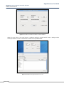
5.2.6 Graphical User Interface
The GUI of the software is developed by using the C++ Qt library. The main window of the software has
double spin boxes for getting the azimuth and elevation values. Text boxes are used to show the actual
values after steering of the antenna. Push buttons are used to perform several tasks like saving and loading
of file etc. A check box is used to activate and deactivate the noise diode.
31
Digital Receiver For SALSA
Chapter 5: Antenna Motion Controller Software
Nabeel Ahmed Durrani
Figure 5-6: The Main GUI of Antenna Motion Controller Software
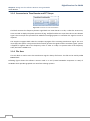
When the user clicks on the save button, a windows method is invoked which shows a dialog window
whose parameters are set so that the file is saved to the specified folder.
Figure 5-7: GUI When Saving Coordinates to a .txt File
32
Digital Receiver For SALSA
Chapter 5: Antenna Motion Controller Software
Nabeel Ahmed Durrani
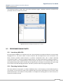
The following window is shown when user clicks load button. Again a windows method is invoked whose
parameters are set to show only .txt files.
Figure 5-8: GUI When Loading Coordinates From a .txt File
5.3
PROGRAM’S MAIN PARTS
5.3.1 Interfacing With RIO
Rio uses Ethernet 100Base-T to interface with a PC. The manufacturer provides the libraries to use Rio with
languages like C++, C#, VB etc. Galil.h is used to interface and interrogate RIO in Linux environment. This
library function provides simple functions to perform complicated tasks. Like a simple command
“g.command (“SB4”)” is used to set high the digital output 4. A simple command like “Galil g(“ip address”)”
is used to perform a very complicated part of connecting the PC with Rio. This command takes care of all
the overhead information used to connect the PC Ethernet port to the RIO. The user does not have to take
care of these overhead and flag information. This library function eases the programming of RIO.
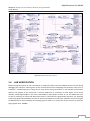
5.3.2 Detecting feedback Pulses
The main problem in the project is to detect feedback pulses, as the frequency of the feedback pulses is
not constant. It varies from 8 to 12Hz, and it depends upon the motor speed which can vary due to wind
speed and direction. The solution to this problem is to sample the incoming pulses as fast so that not a
single pulse would be missed.
33
Digital Receiver For SALSA
Chapter 5: Antenna Motion Controller Software
Nabeel Ahmed Durrani
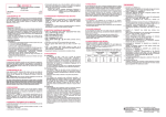
Figure 5-9: Figure Elaborating Detection of Feedback Pulses
In the program the incoming pulses are sampled so fast that there would be a stream of around 70 ones or
zeroes under normal conditions. Then the program looks for the consecutive 1 and 0 or in order words
going down pulses (as marked by a bold square in figure 5-9). The sampling is so fast that we are confident
that not even a single feedback pulse is missed; therefore the program and pointing are so accurate.
5.4
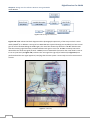
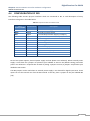
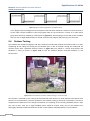
Outdoor Testing
The software was tested thoroughly in lab with real antenna mount but without the antenna load on it. After
completing all the coding and testing all the software parts in lab, an outdoor testing was conducted. An
antenna mount with a parabolic antenna (shown in Figure 2-7) was placed in a windy environment and
hardware is setup (as shown in Figure 5-10) to test the Antenna Motion Controller Software in real
environment.
Figure 5- 10: Antenna Motion Controller software testing in real environment
The antenna is mounted in such a way that the horizontal close switch is in north direction and vertical close
switch is in zenith direction. The main problem in the outdoor testing is the windy environment. In order to
compensate the behaviour of the windy environment, the sampling of the incoming feedback pulses is kept
very fast so that, even not a single feedback pulse would be missed. Every part of the software was
thoroughly checked, tested and verified in the lab, so the software worked perfectly in real conditions.
34
CHAPTER 6
CONCLUSION AND FUTURE WORK
A software receiver for SALSA and a new antenna motion controller we designed, realised and successfully
tested under real operation condition. The antenna motion controller is fully functional and flexible, the
software receiver is performing far better than the existing one with real-time signal processing, less
hardware resources and with the advantage of re-configurability. All the parts of the project/thesis are now to
be integrated to have a fully functional operating system with Software Receiver and Antenna Control
Software running on a PC and to have a single piece of enclosure for all the necessary hardware. This will
ensure maximum integrity and minimum parts in the surroundings of the antenna.
The software receiver shows real time signals (Signal and Reference) which can also be set by the user.
Observations can be made using the (Signal-Reference)/Reference technique which is shown in separate tab
in the software. The software receiver is highly flexible in terms of changing frequency, gain, bandwidth
without changing hardware components. It is not required to switch the frequency from Signal to Reference
because both are shown simultaneously in real time.
In the antenna motion control software, the user enters azimuth and elevation to direct the antenna in the
proper direction (towards Hydrogen line source). The software controls completely the steering of the
antenna, initializing the antenna position, controlling of noise diode and saving and loading antenna position
in some file. In the previous system, the control of antenna is divided in two parts; the C program and Q-radio
(a microcontroller based hardware). But now the antenna is completely controlled by a single C program. This
program is flexible enough that most of the things like number of pulses per degree, position of the closed
switches both in azimuth and elevation directions, initial position of antenna etc can be easily changed.
Further, if one wants to reconfigure RIO for future extensions, one would just need to change some numbers
in program (clearly commented). Antenna motion controller software is also sufficiently flexible to be used
with different antenna mounts because sampling which is used to read feedback pulses is fast enough to
accommodate high frequency feedback pulses as well.
The current receiver system has an option to save the spectrum in a binary format. There are a few extensions
that could also be made to make it a little more versatile. Currently the GnuRadio itself is in development
stage and the save data procedure could be optimized, keeping smooth running of the program when saving
data. The software could also be upgraded for supporting different file formats, save the spectrum that is
currently shown etc, by the use of Python or C++ programming.
The current receiver is designed for the detection of the Hydrogen line and may be slightly modified to detect
some other lines. A new receiver can be built to detect Pulsars based on either filter-bank or employing a
reverse channel filter. A filter-bank consists of a number of narrow-band filters or channels, the output of
each of which is delayed separately by different amount and then are added. This is to remove dispersion
effects that are caused to pulsar signals during their journey through dispersive medium. The other way to
remove dispersion is to employ and anti-dispersive or reverse channel filter that has the characteristics just
opposite of the dispersive medium or channel and will reshape the Pulsar signals. Finally, since Pulsar signals
arrive in the form of pulses with highly accurate timing, one has to take each pulse and add them together to
have enough energy to be detectable.
35
Digital Receiver For SALSA
Chapter 6: Conclusion And Future Work
The following consideration could be taken into account for the extension of the antenna motion controller
software.
First, in the current software files can be saved in standard .fits format, but because of the time limitation of
the project, reading the antenna positions from this standard .fits format is not implemented yet. Second, the
interface between the software receiver developed in GNU radio and the antenna motion controller software,
could be improved even though it is functional as it is. Third, a tracking part could be included in the software
which can lock an object and then track it automatically. Last, there is a possibility of creating interferometer
with two antennas.
36
REFERENCES
[1] http://en.wikipedia.org/wiki/
*2+ Bhushan Billade, “Design of Dual Polarization Sideband Separation Mixer for ALMA Band 5”,
Department of Radio and Space Science, Chalmers University of Technology, Sweden, 2009
[3] Courtesy of Onsala Space Observatory
[4] Per-Simon Kildal, “Foundations of Antennas”, Spring 2009
*5+ Naveen Manicka, “GNU RADIO TESTBED”, University of Delaware
[6] Marcus Leech, VE3MDL, “GnuRadio and USRP: Solderless Breadboarding for the 21st Century”
[7] http://sine.ni.com/nips/cds/view/p/lang/en/nid/207050
[8] http://www.vanu.com/technology/sdr.html
[9] www.pentek.com
[10] www.gnuradio.org
[11] Private Communication with Cathy Horellou, Onsala Space Observatory
[12] http://www.rabbit.com/products/op7200/
[13] www.triomotion.com
[14] http://sine.ni.com/np/app/main/p/ap/motion/lang/en/pg/1/sn/n17:motion,n24:cRIO/
[15] http://www.galilmc.com/products/dmc-17x0.php
[16] User manual for 74xxx series.
[17] http://www.alfaradio.ca/
[18] http://www.oso.chalmers.se/~horellou/OUTREACH/SALSA/radiosweden.pdf
37
Digital Receiver For SALSA
Chapter 6: Conclusion And Future Work
38
APPENDIX A
ANTENNA MOTION CONTROLLER C++ CODE
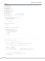
A.1: mainwindow.h
#ifndef MAINWINDOW_H
#define MAINWINDOW_H
#include <QMainWindow>
namespace Ui {
class MainWindow;
}
class MainWindow : public QMainWindow {
Q_OBJECT
public:
MainWindow(QWidget *parent = 0);
~MainWindow();
protected:
void changeEvent(QEvent *e);
private:
Ui::MainWindow *ui;
private slots:
void on_load_clicked();
void on_azimuth_valueChanged(double );
void on_save_2_clicked();
void on_track_clicked();
void on_noise_clicked(bool checked);
void on_OK_clicked();
};
#endif // MAINWINDOW_H
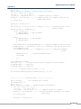
A.2: main.cpp
#include <QtGui/QApplication>
#include "mainwindow.h"
#include "Galil.h"
int main(int argc, char *argv[])
{
QApplication a(argc, argv);
MainWindow w;
w.show();
return a.exec();
}
A.3: mainwindow.cpp
#include "mainwindow.h"
#include "ui_mainwindow.h"
#include<stdio.h>
#include<stdlib.h>
#include <math.h>
#include <ctype.h>
#include <unistd.h>
#include <string.h>
#include <fcntl.h>
#include<iostream>
#include<sstream>
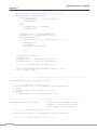
39
Digital Receiver For SALSA
Appendix A
#include<cstring>
#include<cstdlib>
#include<fstream>
#include<qfile.h>
#include<qtextstream.h>
#include<qdir.h>
#include<qapplication.h>
#include<QFileDialog>
#include<fstream>
#include "Galil.h"
float actual_az = 0;
// CLOSE SWITCH AZIMUTH
float actual_el = 95; // CLOSE SWITCH ELEVATION
using namespace std;
MainWindow::MainWindow(QWidget *parent) :
QMainWindow(parent),
ui(new Ui::MainWindow)
{
ui->setupUi(this);
}
MainWindow::~MainWindow()
{
delete ui;
}
void MainWindow::changeEvent(QEvent *e)
{
QMainWindow::changeEvent(e);
switch (e->type()) {
case QEvent::LanguageChange:
ui->retranslateUi(this);
break;
default:
break;
}
}
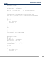
/*------------------------------- Steering Part-------------------------------------*/
void MainWindow::on_OK_clicked()
{
/*------------connection with Rio-------*/
Galil g("192.168.0.24"); // check whether works with global dec
/*-----------getting values from form (.ui)--------- */
float az;
//Azimuth
float el;
//Elevation
az = ui->azimuth->value();
el = ui->elevation->value();
// picking azimuth value from form
// picking elevation value from form
/*---------------- Azimuth Tracking-------------*/
float totalP_az;
//for checking with 3 pulses
int feedbackP_az = 0;
40
Digital Receiver For SALSA
Appendix A
int i = 0;
double feedback_az [99999]; //feedback pulses for azimuth
//if (az > 360.0) az -= 360.0;
//if (az <
0.0) az += 360.0;
//totalP_az = (az-actual_az) * 4; // 4 feedback pulses in 1 degree
totalP_az = (az-actual_az) * 3; // 3 feedback pulses in 1 degree (change to any
number when known)
if (totalP_az<0)
{
totalP_az = totalP_az*(-1);
}
int totalP_az1 = static_cast <int> (totalP_az + 0.5); // converting float to the
nearest integer
while(totalP_az1 != feedbackP_az){
if (az < actual_az){
g.command("SB4"); // Right movement
g.command("SB5");
}
else{
g.command("SB4"); // Left movement
g.command("CB5");
}
std::string num = g.command("MG@IN[8]");// acquiring feedback pulses from RIO
feedback_az[i] = ::strtod(num.c_str(),0);// converting std::string into float
cout<<feedback_az[i];
if ((feedback_az[i-1] == 1) & (feedback_az [i] == 0))//detecting feedback
pulses
{
feedbackP_az++;
// counting feedback pulses
cout<<endl;
}
i++;
}
cout<<feedbackP_az<<endl;
actual_az = az;
// storing current value of azimuth in actual azimuth
g.command("CB4"); // resets Rio
g.command("CB5"); // resets Rio
/*------------putting values in form---------*/
ui->actualaz->setText(QString::number(actual_az, 'f',2));
/*-------------------elevation Part---------------------*/
float totalP_el;
//for checking with 3 pulses
int feedbackP_el = 0;
int j = 0;
double feedback_el [99999]; // feedback pulses for elevation
//if (el > 90.0) az -= 90.0;
//if (el <
0.0) az += 90.0;
//totalP_el = (el-actual_el) * 4; // 4 feedback pulses in 1 degree
totalP_el = (el-actual_el) * 3; // 3 pulses per degree (change to any number
when known)
if (totalP_el<0)
{
totalP_el = totalP_el*(-1);
41
Digital Receiver For SALSA
Appendix A
}
int totalP_el1 = static_cast <int> (totalP_el + 0.5);
while(totalP_el1 != feedbackP_el){
if (el > actual_el){
g.command("SB6"); // counter clock wise
g.command("SB7");
}
else{
g.command("SB6"); //clockwise
g.command("CB7");
}
std::string num2 = g.command("MG@IN[9]");
feedback_el[j] = ::strtod(num2.c_str(),0);
cout<<feedback_el[j];
if ((feedback_el[j-1] == 1) & (feedback_el [j] == 0))
{
feedbackP_el++;
cout<<endl;
cout<<feedbackP_el<<endl;
}
j++;
}
cout<<feedbackP_el<<endl;
actual_el = el;
g.command("CB6"); // resets Rio for elevation
g.command("CB7"); // resets Rio for elevation
/*------------putting values in form---------*/
ui->actualel->setText(QString::number(actual_el, 'f',2));
cout << "end" << endl;
}
/*------------------------------- Noise diode Part----------------------------------*/
void MainWindow::on_noise_clicked(bool noise)
{
/*------------connection with Rio-------*/
Galil g("192.168.0.24"); // check whether works with global dec
if (noise)
g.command("SB2"); //noise diode is on on DO2
if (!noise)
g.command ("CB2"); // noise diode is off on DO2
}
/*-----------------------------------Reset Part-------------------------------------*/
void MainWindow::on_track_clicked()
// when reset button clicked (It resets
antenna to 0 degree azimuth (North)
and 90 degree elevation (zenith))
{
/*-------------connection with Rio--------*/
Galil g("192.168.0.24"); // check whether works with global dec
/*---------------azimuth reset ----------------*/
42
Digital Receiver For SALSA
Appendix A
double reset_az[99999];
int k = 0;
int sum = 1;
// making do-while in this way
g.command("SB4"); // right movement
g.command("SB5"); // right movement
while((sum != 0) & (sum != 48))
// if a contineous stream of 0s or
contineous stream of 1s occurs,
it comes out of loop
{
std::string num3 = g.command("MG@IN[8]");//acquiring azimuth pulses
reset_az[k] = ::strtod(num3.c_str(),0);// converting std::string into double
cout<<reset_az[k];
if (k>50)
// counting number of zeros or ones at close switch
{
sum = 0;
for (int l=50; l>1; l--)
{
sum += reset_az[k-l];
cout<<sum<<"
";
}
}
g.command ("WT5");
k++;
}
g.command("CB4"); // resets Rio for elevation
g.command("CB5");
cout<<"azimuth is reset to 0 degree"<<endl;
/*-------------- Elevation reset --------------*/
double reset_el[99999];
int m = 0;
int sum2 = 1;
g.command("SB6"); // right movement
g.command("SB7"); // right movement
while((sum2 != 0) & (sum2 !=48))
{
std::string num4 = g.command("MG@IN[9]");
reset_el[m] = ::strtod(num4.c_str(),0);
cout<<reset_el[m];
if (m>50)
{
sum2 = 0;
for (int n=50; n>1; n--)
{
sum2 += reset_el[m-n];
cout<<sum<<"
";
}
}
43
Digital Receiver For SALSA
Appendix A
g.command ("WT5");
m++;
}
g.command("CB6"); // resets Rio for elevation
g.command("CB7");
cout<<endl<<"elvation is reset to 100 degree"<<endl;
/*-----------Moving 5 degrees more--------*/
float totalP_el;
int feedbackP_el = 0;
int j = 0;
double feedback_el [99999]; //can be array of bool
float el = 90;
float actual_el = 95;
totalP_el = (el-actual_el) * 3; // 3 feedback pulses in 1 degree (change to
any number when known)
//totalP_el = (el-actual_el) * 4; // 4 feedback pulses in 1 degree
totalP_el = totalP_el*(-1);
int totalP_el1 = static_cast <int> (totalP_el + 0.5);
while(totalP_el1 != feedbackP_el){
g.command("SB6"); //clockwise
g.command("CB7");
std::string num2 = g.command("MG@IN[9]");
feedback_el[j] = ::strtod(num2.c_str(),0);
cout<<feedback_el[j];
if ((feedback_el[j-1] == 1) & (feedback_el [j] == 0))
{
feedbackP_el++;
cout<<endl;
}
j++;
}
cout<<feedbackP_el<<endl;
actual_el = el;
g.command("CB6"); // resets Rio for elevation
g.command("CB7"); // resets Rio for elevation
cout <<endl<<"the actual elevation is 90 now"<<endl;
}
/*-------------------------------Save file Part-------------------------------------*/
void MainWindow::on_save_2_clicked()
{
//opening file dialog to save file
QString fileName = QFileDialog::getSaveFileName(this,tr("Save File"),
"/home/salsa/banade/files",
tr ("Text Files (*.txt)"));
// creating file with the name given by user
QFile file(fileName);
file.open(QIODevice::WriteOnly | QIODevice::Text);
QTextStream out(&file);
44
Digital Receiver For SALSA
Appendix A
// putting data in file
double d1=(ui->azimuth->value());
double d2 = (ui->elevation->value());
QString s1;
QString s2;
s1.sprintf("%.5f", d1);
s2.sprintf("%.5f",d2);
out<<s1<<endl<<s2;
//close file to save
file.close();
}
/*-------------------------------load file Part-------------------------------------*/
void MainWindow::on_load_clicked()
{
// opening file dialog to load file
QString fileName;
fileName = QFileDialog::getOpenFileName(this,
tr("Open File"), "/home/salsa/banade/files", tr("Text Files (*.txt)"));
FILE *in = fopen(fileName.toAscii(), "rt"); //converting Qstring into c string
// read the first line from the file
char buffer[100];
char buffer2[100];
fgets(buffer, 50, in);
fgets(buffer2, 50, in);
// display what we've just read
printf("first line of \"fred.txt\": %s\n", buffer);
printf("first line of \"fred.txt\": %s\n", buffer2);
double f = atof(buffer);
double f2 = atof(buffer2);
cout<<f<<endl;
cout<<f2<<endl;
//putting values in form
ui->azimuth->setValue(f);
ui->elevation->setValue(f2);
// close the stream
fclose(in);
}
45
Digital Receiver For SALSA
Appendix A
46
APPENDIX B
ELECTRICAL DIAGRAM OF AMPLIFIER BOX
47
48
APPENDIX C
INSTALLATION OF SOFTWARES
GnuRadio was installed on Linux-Fedora Core operating system. Following links were used to install and
configure GnuRadio and GRC.
http://gnuradio.org/redmine/wiki/gnuradio
ftp://ftp.gnu.org/gnu/gnuradio/gnuradio-3.2.2.tar.gz
http://gnuradio.org/redmine/wiki/1/GNURadioCompanion
Once everything is installed, the file receiver.grc can be open in GRC and can be run from there. Alternatively,
the python code that is also generated, can be run directly from terminal by typing (in the directory
“RA_Receiver”)
python top_block.py
Following are the instructions to install Antenna Motion Controller software on computer.
Pre-requisite is a personal computer on which Linux (any version) is already installed.
Copy and paste antenna motion controller software along with all of its files in to home folder (copy
folder “banade”).
To download Qt SDK, go to http://qt.nokia.com/downloads. Choose LGPL open source license. Click
the version which suits your machine type (32 or 64 bit) and start download.
After downloading, install QT SDK on your machine. Installation instructions are given on download
page.
This will install Qt library 4.6 and also an editor Qt creator 1.3.1 on your computer. This Qt creator
have already added all the paths and libraries, you don’t have to worry about it anymore.
Now install Galil Tools. Go to http://www.galilmc.com/support/software-downloads.php and click on
link install files under Linux tab. It will lead you to the registration page. Register yourself, its free.
After registration, download and install the latest version of GalilTools. Installation instructions are
available on the same page.
After installation search for “Galil.so”, copy it and paste it in to /usr/lib. This is the easiest way to
locate Galil communication library, otherwise you have to give complete path of “Galil.so” in
banade.pro
Now Antenna Motion controller software is ready to run on this computer. You can directly run
executable file “banade” in the folder “banade” which you have pasted in home folder in step 2 OR
you can load file “banade.pro” in Qt creator and then press Ctrl+R to run the project.
Now you are ready with Antenna Motion Controller Software.
49