1
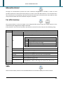
3590EGT TECHNICAL GUIDE
TOUCH SCREEN WEIGHT INDICATOR
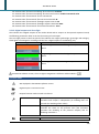
Revision
Last update
Available versions
1.04
01/02/2013
AF01
AF02
AF03
AF04
AF05
AF08
BATCH1
TOTALIZATIONS AND SIMPLE
DOSAGES SYSTEMS
QUANTITY (PIECES, LITRES, ETC.) COUNTING SYSTEMS
VEHICLE WEIGHING SYSTEMS WITH INPUT/OUTPUT
FUNCTION
STATISTICAL CHECK OF PREPACKAGED GOODS
INDUSTRIAL PRICE COMPUTING
WHEEL WEIGHING SYSTEMS WITH VARIOUS
PLATFORMS
SINGLE PRODUCT DOSAGE SYSTEMS, IN LOADING OR
UNLOADING
Page intentionally left blank.
3590EGT TECHNICAL GUIDE
Table of contents
REVISION HISTORY OF DOCUMENTATION ...................................................................................................... 13
1
INSTALLATION.......................................................................................................................................... 15
1.1
Electrical precautionary measures .............................................................................................. 15
1.2
Earthing system ........................................................................................................................... 16
1.2.1
Indicator................................................................................................................................... 16
1.2.2
Load cells and junction box ..................................................................................................... 16
1.2.3
Weighing structure .................................................................................................................. 16
1.2.4
General Notes .......................................................................................................................... 16
1.3
Connection to the load receiver .................................................................................................. 17
1.3.1
Analog load cells ...................................................................................................................... 17
1.3.2
Digital load cells ....................................................................................................................... 18
1.4
2
Serial line connection .................................................................................................................. 21
1.4.1
RS485 connection .................................................................................................................... 21
1.4.2
PC connection .......................................................................................................................... 23
1.4.3
Printer connection ................................................................................................................... 23
TECHNICAL SETUP.................................................................................................................................... 25
2.1
Menu navigation.......................................................................................................................... 27
2.1.1
Numeric input .......................................................................................................................... 28
2.1.2
Alphanumeric input ................................................................................................................. 28
2.1.3
Only one choice selection ........................................................................................................ 29
2.1.4
Multiple selections .................................................................................................................. 29
2.2
Description of the steps............................................................................................................... 29
2.2.1
Calibration ............................................................................................................................... 29
Number of scales/channels ................................................................................................................. 29
Converter channels mode ................................................................................................................... 30
Load cells type ..................................................................................................................................... 30
Load cell DGX mode............................................................................................................................. 31
Number of cells (Scale x) ..................................................................................................................... 31
Number of DGX.................................................................................................................................... 31
Number of cells (DGXx) ....................................................................................................................... 32
WWS communication mode ................................................................................................................ 32
Radio channel configuration................................................................................................................ 32
WWS remote configuration................................................................................................................. 33
Get WWS configuration ....................................................................................................................... 33
Number of decimals ............................................................................................................................ 33
Unit of measure ................................................................................................................................... 34
Number of range ................................................................................................................................. 34
3590EGT TECHNICAL GUIDE
Multi range type .................................................................................................................................. 34
Division of range x ............................................................................................................................... 35
Capacity/Range x ................................................................................................................................. 35
Filtering type........................................................................................................................................ 35
Division for test of stability .................................................................................................................. 36
Zero tracking division .......................................................................................................................... 37
Gravity value setting ............................................................................................................................ 37
Zeroing percentage with ZERO key ..................................................................................................... 37
Automatic zeroing at start up .............................................................................................................. 38
Zeroing percentage at start up ............................................................................................................ 38
Equalisation procedure........................................................................................................................ 38
Calibration procedure.......................................................................................................................... 40
Zero calibration.................................................................................................................................... 42
Calibration points ................................................................................................................................ 43
Example: Calibration of 2 scales (independent channels mode) ......................................................... 43
Example: Calibration of 1 scale with 2 dependent analog channels ................................................... 44
Example: Calibration of 1 scale with 4 RCD digital cells ...................................................................... 44
Example: Calibration of 1 scale with 2 DGX digital cells (4 channels for each DGX) ........................... 45
Example: Calibration of 4 scales with 1 radio WWS digital cell each .................................................. 46
2.2.2
First programming ................................................................................................................... 46
Language.............................................................................................................................................. 46
Access password to setup enabling ..................................................................................................... 47
Access password to setup.................................................................................................................... 47
Message to show at the start up ......................................................................................................... 47
Touch screen calibration ..................................................................................................................... 48
2.2.3
AF0x functions ......................................................................................................................... 48
AF01 and AF05 functions ..................................................................................................................... 48
Totalisation type .......................................................................................................................... 48
Totalisation mode ........................................................................................................................ 48
Totalisation delay ........................................................................................................................ 49
Condition of totalisation .............................................................................................................. 49
Restore tare at the start up ......................................................................................................... 49
Tare before the totalisation......................................................................................................... 49
Tare after the totalisation ........................................................................................................... 50
Add the database tare to the actual tare .................................................................................... 50
Full weighs list warning................................................................................................................ 50
AF02 functions ..................................................................................................................................... 51
Minimum percentage for sampling ............................................................................................. 51
Type of the average piece weight update ................................................................................... 51
Unit of measure of the average piece weight ............................................................................. 51
Number of decimals of the average piece weight....................................................................... 52
3590EGT TECHNICAL GUIDE
Quantity description .................................................................................................................... 52
Number of decimals of the quantity ........................................................................................... 52
Output function quantity/weight ................................................................................................ 53
Automatic zeroing before sampling ............................................................................................ 53
Scale of sampling ......................................................................................................................... 53
AF03 functions ..................................................................................................................................... 54
Weighing mode............................................................................................................................ 54
Enabling A+B function mode ....................................................................................................... 54
Memorisation type of input weigh .............................................................................................. 54
ID code generation ...................................................................................................................... 55
Scale management in input/output ............................................................................................ 55
AF04 functions ..................................................................................................................................... 55
Check type ................................................................................................................................... 55
Production lines number ............................................................................................................. 56
Automatic print of the sampling report ...................................................................................... 56
Ask lot description before the sampling...................................................................................... 56
Lot judgement at each sample .................................................................................................... 57
Tare acquisition before the sampling .......................................................................................... 57
Totalisation only in tolerance ...................................................................................................... 57
Tolerance range and weigh intervals........................................................................................... 58
AF08 functions ..................................................................................................................................... 59
Printout text for WHEEL .............................................................................................................. 59
Printout text for AXLE .................................................................................................................. 59
Automatic zeroing of weighs list ................................................................................................. 60
Number of decimals of the coordinates ...................................................................................... 60
Unit of measure of the coordinates ............................................................................................ 60
BATCH1 functions ................................................................................................................................ 61
Dosage type selection.................................................................................................................. 61
Configured scale .......................................................................................................................... 61
Maximum dosable weight ........................................................................................................... 61
Flight waiting time ....................................................................................................................... 62
Zero tolerance weight ................................................................................................................. 62
Start threshold for silo filling ....................................................................................................... 63
End threshold for silo filling ......................................................................................................... 63
Filling duration time .................................................................................................................... 63
5
3590EGT TECHNICAL GUIDE
Filling start-up .............................................................................................................................. 64
Total unloading end threshold .................................................................................................... 64
Wait for discharge end ................................................................................................................ 64
Wait time for manual dosage end ............................................................................................... 65
Maximum dosage duration ......................................................................................................... 65
Maximum weight variation in time ............................................................................................. 66
Batching peak elimination time ................................................................................................... 66
Peaks filter ................................................................................................................................... 66
Wait stability time ....................................................................................................................... 67
Data reading wait ........................................................................................................................ 67
Filtering time................................................................................................................................ 67
Weight display on unloading ....................................................................................................... 68
Manual dosage display screen..................................................................................................... 68
Slow execution mode .................................................................................................................. 68
Relay tapping on of slow mode ................................................................................................... 69
Relay tapping off of slow mode ................................................................................................... 69
Flight correction percentage ....................................................................................................... 69
Flight correction range ................................................................................................................ 70
Production programme enabling ................................................................................................ 70
Formula weight setting mode ..................................................................................................... 71
Print formula on total weight ...................................................................................................... 71
Formula selection mode .............................................................................................................. 72
Enabling tolerance test ................................................................................................................ 72
On time of tolerance relay........................................................................................................... 72
Pulses per litre ............................................................................................................................. 73
Flight wait time ............................................................................................................................ 73
Target volume.............................................................................................................................. 73
Slow volume ................................................................................................................................ 74
Flight volume ............................................................................................................................... 74
Minimum flow rate ...................................................................................................................... 74
Alarm time ................................................................................................................................... 75
Speed relay on time ..................................................................................................................... 75
Speed relay off time .................................................................................................................... 75
2.2.4
Generic functions..................................................................................................................... 76
Totalisation mode ................................................................................................................................ 76
3590EGT TECHNICAL GUIDE
Ask before reset the total .................................................................................................................... 76
Tare type .............................................................................................................................................. 77
Additional tare before output weigh................................................................................................... 77
Tare limitations for direct sale............................................................................................................. 77
Enabling of automatic tare .................................................................................................................. 78
Weighing mode reactivation ............................................................................................................... 78
Automatic calibration warning (months) ............................................................................................ 78
Automatic calibration warning (weighs) ............................................................................................. 79
Motherboard warming time ................................................................................................................ 79
Weight window zoom enabling ........................................................................................................... 79
Weight window zoom activation time ................................................................................................ 80
2.2.5
Shortcuts.................................................................................................................................. 80
Keyboard customisation (Function keys: F1, ..., F10) .......................................................................... 80
Keyboard customisation (Other keys: TARE/ESC, ...) .......................................................................... 80
Toolbar customization (Button title) ................................................................................................... 81
Toolbar customization (Button function) ............................................................................................ 81
Functions sequence ............................................................................................................................. 82
Example: Sequence 1 linked to the F1 key ........................................................................................... 83
2.2.6
Databases ................................................................................................................................ 86
Enabling database................................................................................................................................ 86
Number of decimals ............................................................................................................................ 86
Unit of measure ................................................................................................................................... 86
Safety password enabling .................................................................................................................... 87
Safety password................................................................................................................................... 87
AF01 Databases customisation............................................................................................................ 87
Article dtb customization ............................................................................................................ 87
Customer dtb customization ....................................................................................................... 88
AF02 Databases customisation............................................................................................................ 88
Article dtb customization ............................................................................................................ 88
Customer dtb customization ....................................................................................................... 89
AF03 Databases customisation............................................................................................................ 89
Customer dtb customization ....................................................................................................... 89
Material dtb customization ......................................................................................................... 89
Vehicle dtb customization ........................................................................................................... 90
AF04 Databases customisation............................................................................................................ 90
Article dtb customization ............................................................................................................ 90
AF05 Databases customisation............................................................................................................ 91
Products dtb customization......................................................................................................... 91
Customer dtb customization ....................................................................................................... 91
AF08 Databases customisation............................................................................................................ 92
Vehicle dtb customization ........................................................................................................... 92
7
3590EGT TECHNICAL GUIDE
BATCH1 Databases customisation ....................................................................................................... 93
Formula dtb customization.......................................................................................................... 93
2.2.7
Input texts................................................................................................................................ 94
2.2.8
Serial ports ............................................................................................................................... 95
Serial ports function mode .................................................................................................................. 95
Printer port configuration ................................................................................................................... 95
Baud rate ..................................................................................................................................... 95
Parity type.................................................................................................................................... 96
Word length ................................................................................................................................. 96
Stop bit ........................................................................................................................................ 97
CTS status .................................................................................................................................... 97
CTS Emulation Chars Number...................................................................................................... 97
CTS Emulation Interval ................................................................................................................ 98
XON Character ............................................................................................................................. 98
XOFF Character ............................................................................................................................ 98
1st Reset command byte .............................................................................................................. 98
2nd Reset command byte ............................................................................................................. 99
3rd Reset command byte .............................................................................................................. 99
4th Reset command byte .............................................................................................................. 99
Second CTS status ........................................................................................................................ 99
Show the CTS error .................................................................................................................... 100
Printer power supply ................................................................................................................. 100
Protocol ..................................................................................................................................... 100
Pc port configuration ......................................................................................................................... 101
Baud rate ................................................................................................................................... 101
Parity type.................................................................................................................................. 101
Word length ............................................................................................................................... 102
Stop bit ...................................................................................................................................... 102
CTS status .................................................................................................................................. 102
CTS Emulation Chars Number.................................................................................................... 103
CTS Emulation Interval .............................................................................................................. 103
Protocol ..................................................................................................................................... 103
Communication mode ............................................................................................................... 104
485 address................................................................................................................................ 104
Auxiliary port configuration............................................................................................................... 105
Baud rate ................................................................................................................................... 105
3590EGT TECHNICAL GUIDE
Parity type.................................................................................................................................. 105
Word length ............................................................................................................................... 105
Stop bit ...................................................................................................................................... 106
CTS status .................................................................................................................................. 106
CTS Emulation Chars Number.................................................................................................... 106
CTS Emulation Interval .............................................................................................................. 107
Protocol ..................................................................................................................................... 107
Send data for Repeater DC ........................................................................................................ 107
Network configuration ...................................................................................................................... 108
Node group ................................................................................................................................ 108
Node ID ...................................................................................................................................... 108
IP mode ...................................................................................................................................... 108
IP address................................................................................................................................... 109
Subnet mask .............................................................................................................................. 109
Automatic db alignment ............................................................................................................ 109
Network name ........................................................................................................................... 110
Send network configuration ...................................................................................................... 110
2.2.9
Printout .................................................................................................................................. 110
Printout headings .............................................................................................................................. 110
2.2.10 External keyboard – Barcode reader ..................................................................................... 110
Keyboard port use ............................................................................................................................. 110
External pc keyboard type ................................................................................................................. 111
Barcode reader serial port................................................................................................................. 111
2.2.11 Remote scale ......................................................................................................................... 111
Management enabling ...................................................................................................................... 112
Network remote scales...................................................................................................................... 112
Example: 2 instruments with one weighing system only ................................................................... 112
String terminator ............................................................................................................................... 113
Weight start position ......................................................................................................................... 114
Weight length .................................................................................................................................... 114
Type of the weight ............................................................................................................................. 114
Tare start position ............................................................................................................................. 115
Tare length......................................................................................................................................... 115
Tare type start position ..................................................................................................................... 115
Total length of the string ................................................................................................................... 115
Stability readings ............................................................................................................................... 116
Stability weight difference................................................................................................................. 116
Stability type ...................................................................................................................................... 116
Stability start position........................................................................................................................ 117
9
3590EGT TECHNICAL GUIDE
Stability/Instability string................................................................................................................... 117
Rounding function on the weight ...................................................................................................... 117
Number of decimals .......................................................................................................................... 118
Unit of measure ................................................................................................................................. 118
Division .............................................................................................................................................. 118
Capacity ............................................................................................................................................. 119
Zero function ..................................................................................................................................... 119
Tare function ..................................................................................................................................... 119
Preset tare function ........................................................................................................................... 120
Tare command ................................................................................................................................... 120
Preset tare command ........................................................................................................................ 120
Weight request interval ..................................................................................................................... 121
Weight request command ................................................................................................................. 121
Command terminator ........................................................................................................................ 121
Example: Configuration with a DFW06 as remote scale set with extended string ............................ 121
2.2.12 Digital outputs and Cross light............................................................................................... 123
Function mode................................................................................................................................... 123
Function ............................................................................................................................................. 124
Contact status .................................................................................................................................... 126
Condition for activation ..................................................................................................................... 126
Hysteresis .......................................................................................................................................... 127
Associated scale................................................................................................................................. 127
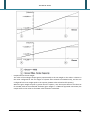
Example: Activation on the gross weight and functioning with hysteresis ....................................... 128
Example: Activation on the negative net weight and functioning with hysteresis............................ 128
2.2.13 Digital inputs .......................................................................................................................... 129
Function ............................................................................................................................................. 129
Example: Input on “OUT1 and OUT2 for dosage” function ............................................................... 130
2.2.14 Remote control ...................................................................................................................... 131
Type ................................................................................................................................................... 131
Function ............................................................................................................................................. 132
2.2.15 Analog output ........................................................................................................................ 132
Expansion board slot ......................................................................................................................... 134
Function ............................................................................................................................................. 135
Value related to full capacity ............................................................................................................. 135
Value related to unloaded scale ........................................................................................................ 135
Value related to underload ............................................................................................................... 135
2.2.16 Backup & Restore .................................................................................................................. 136
Backup of the configuration .............................................................................................................. 136
Clearing of automatic calibration warning ........................................................................................ 136
Restore keys ...................................................................................................................................... 136
Databases initialization...................................................................................................................... 136
Restore printouts ............................................................................................................................... 137
Alibi memory initialization................................................................................................................. 137
Cancellation of the buffered RAM ..................................................................................................... 137
3590EGT TECHNICAL GUIDE
Restore functioning settings .............................................................................................................. 137
Restore all settings ............................................................................................................................ 137
2.2.17 Diagnostic .............................................................................................................................. 138
2.3
Functions list .............................................................................................................................. 138
2.3.1
Available functions for all software versions......................................................................... 138
2.3.2
Available functions for AF0x software version only .............................................................. 141
3
AF01 functions list ............................................................................................................................. 141
AF02 functions list ............................................................................................................................. 141
AF03 functions list ............................................................................................................................. 142
AF04 functions list ............................................................................................................................. 143
AF05 functions list ............................................................................................................................. 144
AF08 functions list ............................................................................................................................. 146
BATCH1 functions list ........................................................................................................................ 147
FIRST USE ............................................................................................................................................... 149
4
LOGO CUSTOMISATION ......................................................................................................................... 153
5
MAIN SCREEN CUSTOMIZATION............................................................................................................ 155
5.1
Customizable area ..................................................................................................................... 155
5.2
Screen commands ..................................................................................................................... 155
5.3
Variable data parameters .......................................................................................................... 158
5.4
Format errors............................................................................................................................. 159
5.5
Display customization example ................................................................................................. 160
6
SERIAL COMMUNICATION ..................................................................................................................... 161
6.1
Transmission protocols .............................................................................................................. 161
6.2
Communication modes.............................................................................................................. 164
7
PRINTOUT FORMATTING ....................................................................................................................... 167
8
ALIBI MEMORY ...................................................................................................................................... 169
9
AVAILABLE EXPANSION BOARDS ........................................................................................................... 171
10
AVAILABLE OPTIONS .......................................................................................................................... 173
11
AVAILABLE PC TOOLS ......................................................................................................................... 175
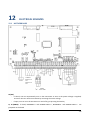
12
ELECTRICAL SCHEMES........................................................................................................................ 177
12.1
MOTHERBOARD ......................................................................................................................... 177
12.2
I/O EXPANSION BOARD ............................................................................................................. 180
12.3
DISPLAY BOARD ......................................................................................................................... 181
11
3590EGT TECHNICAL GUIDE
Page intentionally left blank.
REVISION HISTORY OF DOCUMENTATION
Revision
01.00
01.01
01.02
01.03
01.04
Software versions
EGT-AF01
EGT-AF03
Description
Supported version: AF01
Supported version: AF03
EGT-AF01
EGT-AF03
EGT-AF05
Supported version: AF05
Preamble description for the functions that accept it
Network remote scale description (with example) for the
AF03 software version
EGT-AF01
EGT-AF02
EGT-AF03
EGT-AF04
EGT-AF05
EGT-AF01
EGT-AF02
EGT-AF03
EGT-AF04
EGT-AF05
Supported version: AF02
Supported version: AF04
German language available for the AF01 software version
EGT-AF01
EGT-AF02
EGT-AF03
EGT-AF04
EGT-AF05
EGT-AF08
EGT-BTC1
German language available for the AF03, AF04, AF05
software versions
Modified activation delay time of the zoom function from
minutes to seconds
Modified the number of objects per screen from 20 to 30 in
the main screen customization
Supported version: AF08
Supported version: BATCH1
German language available for the AF02 software version
Modified the number of objects per screen from 30 to 50 in
the main screen customization (30 touchable objects only)
New commands for the main screen customization (Progress
bar and Skip commands)
New function for digital inputs and remote control keys:
Show “-------” on the display and disable the keyboard
1
INSTALLATION
To obtain the best results it is recommended to install the indicator and the platform (or transducer) in a
place with the following conditions:
- a flat, level surface on which to rest;
- stable and vibration free;
- no dust or strong vapours;
- no draughts;
- make sure the platform is level or that the loading cells are resting evenly;
- moderate temperature and humidity (15-30°C and 40-70%);
- do not install anywhere where there is the risk of explosion;
- all the indicator connections have to be made respecting the rules applicable in the zone and in the
installing environment. Respect the recommended electrical precautionary measures described in
section 1.1;
- make sure that the grounding is made correctly, see section 1.2;
- everything not expressly described in this manual has to be considered as improper use of the
equipment;
- avoid welding with load cells installed;
- use waterproof sheaths and couplings in order to protect the load cell cables;
- use a waterproof junction box to connect the cells.
1.1
Electrical precautionary measures
Please follow the listed precautions:
- mains power supply is restricted to within ± 10% of the rated voltage;
- electric protections (fuses etc.) are provided by the technician installing the instrument;
- respect the recommended minimal distances that are mentioned for the various cable categories;
- the extension leads of the load cells or signal amplifiers, used for the connection of the serial ports
and analogue output must be within the allowed maximum lengths, see section 1.2;
- the extension leads of the load cells or signal amplifiers must be screened. In addition they must be
laid on their own in a raceway or metal pipe as far away as possible from the power supply cables;
- install “RC” filters on the contactor coils, on the solenoid valves and on all devices producing
electric disturbances;
- if it is possible that condensation could form inside the weight transmitter it is advisable to leave
the instrument powered at all times;
- every shielded cable or not (for instance PC cable, cell cable, power supply cable) connected to the
indicator should be as shorter as possible, then you have to come out of the shield the minimum
length of cable, then connect to the terminal box;
- if the indicator is situated inside an electric panel, the power supply cable should be a shielded
cable as shorter as possible, distant from every coil supply cable, inverter, electromotive force, etc.
and in addition dedicate an uncoupler transformer in order to feed the indicator only.
15
INSTALLATION
1.2
Earthing system
For the right earthing and the optimal functioning of the system, it is necessary to connect the indicator,
the load cells, the possible junction box and the weighing structure to the earth.
All earthing cables must have the shortest possible length in order to minimize their resistance.
1.2.1 Indicator
Connect the external earthing of the indicator to the earth through copper cables having at least a 16 mm2
cross-section.
1.2.2 Load cells and junction box
The earthing must be done by connecting the earthing cables to a ground bar with cables having a crosssection of at least 16 mm2 and by connecting the ground bar to a ground pole with a cable having a crosssection of at least 50 mm2.
-
-
-
In the case the load cells are connected to the indicator through a junction box, it is necessary to
connect the sheathing both of cells cables and of indicator cable to the earthing of the junction box
(refer to the junction box manual) and connect this to the earth through copper cables having at
least a 16 mm2 cross-section.
If the load cells are connected directly to the indicator (without the use of the junction box), one
should connect the shielding of the load cell cables to the grounding point (or earthing bar) inside
the container.
If the weighing system concerns large and/or outdoor structures, like weighbridges, and the
junction box is connected to the indicator in a distance that is greater than 10 m, or in the presence
of noise, the cable shield must be earthed both in the junction box and in the indicator, and the
two ground leads must be connected with an earth cable having a cross-section of at least 16 mm2 .
1.2.3 Weighing structure
Connect the weighing structure and the possible connected structures (for example silos that release
material on the weighing structure) to the earth through copper cables having at least a 16 mm2 crosssection.
Furthermore it is necessary that for each cell, one connects the upper part with the lower part of the load
cell through a copper braid section not less than 16 mm2; the upper part must be short-circuited with the
surface of the weighing structure and the lower part must be grounded through a copper braid section not
less than 16 mm2.
1.2.4 General Notes
16
All the grounding cables must have an adequate length, in order to obtain an overall resistance of
grounding system less than 1Ω.
In the case the weighing system regards great and/or outdoor structures, like weighbridges:
the grounding connection is to be made by connecting the grounding cables to a grounding
bar and the grounding bar to the grounding pole with a cable section not less than 50 mm2;
the cable cross-section must be greater (for example 50 mm2 instead of 16 mm2 and 100
mm2 instead of 50 mm2), because the voltage into play is greater (for example
thunderbolts);
INSTALLATION
1.3
the ground pole must be positioned at a distance of at least 10 meters from the
weighbridge structure;
one needs to open the SENSE inside the indicator in order to offset the drifts due to the
increase in temperature.
One should check and remove, if necessary, the connection between the earth and the neutral wire
of the electrical installation.
Connection to the load receiver
1.3.1 Analog load cells
After having followed the instructions regarding the platform or the load receiver, the screened cable
leading from the load cell(s) must be connected to the instrument through the CELL1 terminal board and
the CELL1, CELL2, CELL3, CELL4 connectors; see section 12.1.
The CELL1 terminal board of the indicator may be connected to the 6-wire load receiver (with use of SENSE),
or simply 4-wire; for this, through jumper J7 and J8 it is possible to choose whether to short-circuit the
SENSE with the POWER SUPPLY (jumpers closed) or not (jumpers open). The sense allows compensating for
any drops in voltage in the part of the cable that connects the instrument to the transducer. It is useful
when the distance between the indicator and the transducer is greater than 10 m.
The 4-pin connectors instead allow just the 4-wire connection.
To make the connection qualified personnel must open the instrument (see terminal board connections
section 12.1).
TAKE NOTE: if there is just one LOAD RECEIVER, it is possible to make a 6-wire connection (use of sense)
directly with the terminal board, removing the J7 and J8 jumpers.
If there are two or more LOAD RECEIVERS, one should close the J7 and J8 jumpers (sense and power supply
are short-circuited) and make the 4-wire connection.
Normally the indicator comes already connected to the platform and is ready to use. If this is a LEGAL FOR
TRADE instrument, access to the connection will be subject to a legal SEAL.
Follow the instructions for preparing the platform for use.
17
INSTALLATION
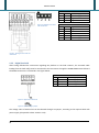
Figure 2. Analog 4 wires load
cell connection
1
2
3
4
AMP4 CONNECTOR
EXC+ Power supply +
EXC- Power supply SIG+
Signal +
SIGSignal -
25
26
27
28
29
30
SIG+
SIGSEN+
SENEXC+
EXC-
TERMINAL
Signal +
Signal Reference +
Reference Power supply +
Power supply -
Figure 1. Analog 6 wires load cell
connection
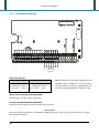
1.3.2 Digital load cells
After having followed the instructions regarding the platform or the load receivers, the screened cable
leading from the load cell(s) must be connected to the instrument through the COM3 RS485 terminal board.
The RS485 connection is illustrated in the figure below.
20
21
22
23
TERMINAL
GND
Power supply +Vdc
Power supply +
TX+/RX+ Line 485 A(+)
TX-/RX- Line 485 B(-)
Figure 3. Digital cell connection
Figure 4. Power voltage jumper
The voltage value of terminal 21 can be selected through J13 jumper, according to the required load cells
power supply (the possible values are 6V or 12V).
18
INSTALLATION
TAKE NOTE: In the case of digital load cells connected to a digital junction board, connect the COM3 RS485
terminal board of the indicator to the RS485 port of the junction board, by following the relative manual
and the 1.4.1 section.
In the case of ring connection of more digital junction boards or DGX load cell, connect the COM3 RS485
terminal board of the indicator to the RS485 port of the first junction board/DGX, by following the relative
manual the 1.4.1 section.
The indicator (AF03 and AF08 software versions only) manages the following digital cell types:
- DGX
- RCD
- CCI AD
- RCD3D
- C16i
In most cases in order to avoid to make a jumper connection between the cells one uses a junction box
which is connected to the indicator on the terminals dedicated to the 485 port. In between the terminals
one needs to apply 2 Pull Up resistances and a termination one in order to have a minimum 0,2 V voltage
between A(+) and B(-) (terminals 22 and 23), how it’s illustrated in the figure:
Figure 5. Digital cell connection to junction box
19
INSTALLATION
In the Figure 6 it’s illustrated the connection of the C16i load cells to the indicator. In this case it’s necessary
a SC232/422B converter to connect it directly to the pc serial port pins (the Serial ports function mode
must be set equal to “1=Aux 2=Printer 3=Pc”).
The connection of the cells to the converter must be made through the junction box or in parallel mode (as
described in the scheme).
Figure 6. C16i Digital cell connection
For these cells it is necessary to programme a few parameters of the configuration programme of the C16i
cell, which may be accessed by connecting the converter to the PC.
By entering in Parameters Basic settings one sets the type of filter one wants to use and the check sum
is enabled:
By entering in Parameters Communication it is necessary to insert the COF format and the ASCII
delimitation as shown in figure:
20
INSTALLATION
1.4
Serial line connection
The connection of the serial ports must be made by technical personnel who knows the procedures on the
basis of the user’s needs. The data transmission cable must be kept away from the AC power supply lines.
!! REMOVE VOLTAGE BEFORE OPENING THE INSTRUMENT !!
1.4.1 RS485 connection
Below is the RS485 connection of the indicator in the COM3:
22 (A+)
23 (B-)
TERMINAL
TX+/RX+ Signal +
TX-/RX- Signal -
On the same RS485 line it’s possible to connect up to 32 devices, among indicators, digital load cells, DGX
conversion cards or 485/232 signal converter.
Figure 7. Electrical diagram of RS485 connection
-
-
Use a STP (Shielded Twisted Pair) cable in order to make the connection (twisted and shielded
pair/s with single shielding for each pair through aluminum band and total shielding through
external sheathing).
The maximum reachable length from the line with the use of the appropriate cable for RS 485
connections, the twisted 2x24 AWG duplex cable, shielded with external sheathing + aluminium
band, is of about 1200 meters.
21
INSTALLATION
-
-
-
-
-
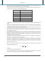
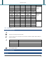
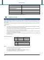
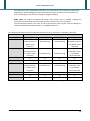
With very long cables, the cable capacity (normally near 50pF/m) starts being a dominant factor in
the power consumption and increases with the increase of speed.
This implies that the maximum distance cannot be covered with the maximum possible speed. For
an approximate value, one can consult the following table:
Baud rate
Total capacity of the cable (pF)
1200
2400
4800
9600
19200
38400
57600
115200
400000
200000
100000
50000
25000
12000
8000
4000
As a general rule, if one has any doubts, it is always preferable to choose the cable with a greater
section.
Verify that the grounding satisfies the requirements of section 1.2. Especially, all the digital masses,
as well as the analogue masses, and the power circuits, must be connected to the grounding bar
and this last one must be connected to the grounding pole.
The shielding can be connected into a single point of the entire network (as shown in Figure 1) or
both its ends, however it’s important that all the masses have the same potential, in order to avoid
the forming of current rings.
On the RS485 network normally one connects 2 termination resistances equal to the characteristic
impedance of the cable (typically 120 Ω, see Figure 7), ONLY on the 2 devices which are at the 2
ends of the ring connection (for example indicator and last device). The terminal resistance is not
supplied with the ports of the indicator.
The difference of potential between the A(+) and B(-) terminals in rest conditions (for example with
instrument in set-up phase), must be of at least 0,2 V.
To create a resistive divider which maintains this difference of potential also when all the
transmitters are disabled, inert in the RS485 port of the indicator where there are the termination
resistances, the polarisation or fail-safe resistances (RFS in Figure 7). The value of these resistances
is between 390 Ω and 2,2 kΩ.
NOTE: in particular, the value of each of these resistances must be greater than the value
calculable through the formula:
RFS
V
dc 1
2 0,2
Req
in which:
Vdc is the power supply voltage of the line
Req is the overall resistance to the A(+) a B(-) heads, supplied by the parallel of the 2 termination
resistances and all the input resistances of the devices connected to the bus.
22
INSTALLATION
-
-
-
FOR EXAMPLE:
Presuming that a connection has 120 Ω as termination resistance and 32 connected devices, each
having an input impedance of 12 kΩ. The Vdc power supply is 5 V.
One calculates Req , equal to about 52 Ω, and RFS which must be at least equal to 624 Ω.
The connection between the indicator and the digital load cells is made with RS485 protocol in the
COM3 configured as Auxiliary port. The indicator can be connected with up to 16 digital load cells.
It’s possible to connect the indicator to digital load cells with 485 4-wire protocol through 422/232
converter. In this case one is required to connect the double TX of RS422 cable to TX+ and TXconverter’s pins and the double RX of RS422 cable to RX+ and RX- converter’s pins
In case of connection with non Dini Argeo devices, there may be different ways of line marking:
generally one presumes that the A/B indication corresponds to the +/- and HI/LO markings, but this
is not always true. Therefore, if the device does not function, one should try inverting the
connections even if everything seems to be correct.
For the correct functioning of the digital load cells, one should, in any case respect all the rules
given in the relative specific manuals.
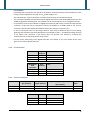
1.4.2 PC connection
INDICATOR
TX
RX
GND
INDICATOR
RJ45
connector
TX (6)
RX (3)
GND (5)
9 pin
Collector
2
3
5
Color
Pink
Yellow
Grey
9 pin
Color
Collector
2
3
5
Orange
Blue/White
Green/White
1.4.3 Printer connection
INDICATOR
TX
CTS
GND
WTY280 /SMT80
9pin (female)
3
4
7
TMU295/LX300
25pin (female)
3
20
7
LP542 Plus /TTP243/SMTPLUS
9pin (female)
3
8
5
INDICATOR
TPR
Standard cable
GND
CTS
TX
GND
CTS
RX
Black
Yellow
Grey
Standard
cable
Pink
Brown
Grey
23
INSTALLATION
INDICATOR
+VP e +VC
GND e GND
24
TPR power supply
TPR
Terminal box
Red and
Orange
Black
and
Black
5 Vaux
16 GND
2
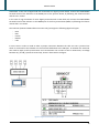
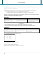
TECHNICAL SETUP
By “Technical setup” environment we mean a certain menu inside which all the indicator operating
parameters can be set.
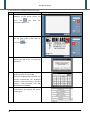
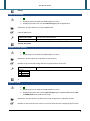
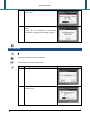
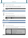
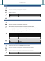
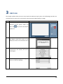
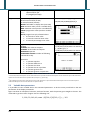
To enter it, if the access password is disabled (Access password to setup enabling), follow these steps:
Step
Description
Screen
1
Connect the power cord of the
indicator to the power socket and
press the
key
instrument powers on
2
the
While the scale logo is displayed touch
the top right corner of the screen or
press the
3
until
key
The scale sets the setup menu
environment and displays the screen
of the figure
25
TECHNICAL SETUP
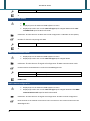
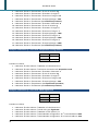
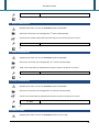
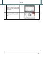
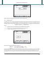
If the password is enabled follow these steps:
Step
Description
1
Connect the power cord of the
indicator to the power socket and
press the
key
instrument powers on
2
until
the
While the scale logo is displayed touch
the top right corner of the screen or
press the
key
3
If one wants to access to the complete
setup press Yes button to insert the
password
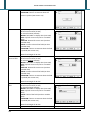
4
Insert the password substituting the
displayed value and press OK.
If one has forgotten the password, one
should communicate the displayed
number to the manufacturer, who will
supply a valid password JUST FOR
THAT SPECIFIC NUMBER
The scale sets the setup menu
environment and displays the screen
of the figure
5
26
Screen
TECHNICAL SETUP
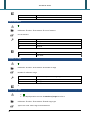
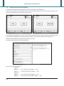
6
If the password value is not valid the
scale sets the partial setup menu
environment
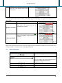
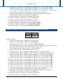
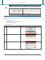
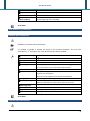
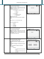
In the first level of the technical menu, in the upper part of the display, can appear the following texts in
parentheses:
Text
Description
Screen
In case of instrument for internal use
only: when the jumper J1 of the
motherboard is opened
INTERNAL USE ONLY
In case of approved instrument (M):
when the jumper J1 of the motherboard
is closed
LEGAL FOR TRADE
NOTE: If the contrast of the screen is too low or high we have a possibility to adjust this contrast with a LCD
contrast trimmer - see section 12.3, drawing display board.
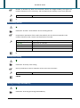
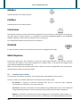
2.1
Menu navigation
Button
Function
Scroll the menu pages
Enters into the parameter setting / next menu
level.
The text in bold is the name of the parameter /
menu level, the bottom text is the
configuration value
Returns to the last menu level
Exit from the setup environment
27
TECHNICAL SETUP
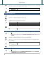
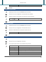
When you exit from the setup, a message appears on the display as described in the table:
Condition
Description
Screen
Setup not If one press Yes button, the indicator
changed restarts.
If one press No button, the indicator
remains in the setup menu
environment.
Setup
changed
If one press Yes button, the setup is
stored and the indicator restarts.
If one press No button, the indicator
restarts without saving the changes.
If one press Cancel button, the
indicator remains in the setup menu
environment.
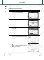
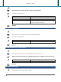
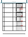
2.1.1 Numeric input
Screen
Function
Allows to insert a numeric value within the
range
0…9: numbers
.: decimal point
+/-: positive or negative sign
/ * - +: arithmetic operations
C: clears all the value
BkSp: backspace
OK: exit saving the value
Esc: exit without saving the value
Screen
Function
Allows to insert a alphanumeric text.
: scroll left or right
Clear: clears all the text
BkSp: backspace
2^F: switches to special characters
Shift: changes the character case and switches
between letter and number modes
OK: exit saving the text
Esc: exit without saving the text
NOTE: on the first pressed key all the field is
replaced
2.1.2 Alphanumeric input
28
TECHNICAL SETUP
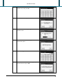
2.1.3 Only one choice selection
Screen
Function
Allows to select only one value of the
parameter
OK: confirm the selection and exit
Cancel: exit without confirming
Screen
Function
Allows to select more values of the parameter
OK: confirm the selection and exit
Cancel: exit without confirming
2.1.4 Multiple selections
2.2
Description of the steps
In the parameter description the used symbols are:
Attention: Limitation of the parameter
M
With approved instrument (when the J1 jumper of the motherboard is closed),
the parameter could be read only or not displayed or set with some values
only
CE-M
It identifies the available value only for the parameter when the instrument is
approved
Full path in the setup environment
Description
Available values
Default value
It identifies an advanced function explained in the user manual
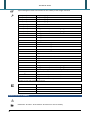
2.2.1 Calibration
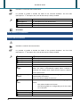
Number of scales/channels
M
Calibration Scale selection Number of scales/channels
AF03 and AF08 software versions: Number of connected scales
Other software versions: Number of connected scales if the Converter channels
mode is set equal to Independent mode or the number of channels if the Converter
29
TECHNICAL SETUP
channels mode is set equal to Dependent mode
Remote scale(1)
1(2)
...
4(3)
Remote scale only
1 scale
4 scales
(1)
Not available in the AF08 and BATCH1 software versions or when one sets the Barcode reader serial port equal to Auxiliary
port
(2)
Not available when one sets the Converter channels mode equal to Dependent mode
(3)
Exception:
2 AF03 software version
8 AF08 software version
1
Converter channels mode
M
Not displayed in the AF03 and AF08 software versions
Calibration Scale selection Converter channels mode
Converter channels mode: independent or dependent
Independent mode
Dependent mode
Instrument connected to independent channels
Instrument connected to dependent channels
Independent mode
Load cells type
M
Displayed just in the AF03 and AF08 software versions
Calibration Scale selection Load cells type
Type of used cells: analog or digital
Analog
Digital DGX
Digital RCD
Digital CCI AD
Digital RCD3D
Digital C16i
Digital WWS
30
Analog cells
TECHNICAL SETUP
Analog
Load cell DGX mode
M
Displayed just in the AF03 and AF08 software versions
Displayed just when one sets the Load cells type equal to Digital DGX
Calibration Scale selection Load cell DGX mode
Load cell DGX mode
Junction box mode
Multi-cells mode
For use of the manufacturer
Conversion into digital of each single analog load cell
Junction box mode
Number of cells (Scale x)
M
Displayed just in the AF03 and AF08 software versions
Calibration Scale selection Number of cells (Scale x)
Number of the connected analog channels or digital cells for each scale
1 ~ 16(1)
(1)
Exception:
4
Analog
24 Digital DGX
8
Digital CCI AD
1
Number of DGX
M
Displayed just in the AF03 and AF08 software versions
Displayed just when one set the Load cells type equal to Digital DGX and the Load
cell DGX mode equal to Multi-cells mode
Calibration Scale selection Multi-cells mode configuration Number of DGX
Number of DGX cards that are used to convert the total load cells composing all the scales
31
TECHNICAL SETUP
1 ~ 24
1
Number of cells (DGXx)
M
Displayed just in the AF03 and AF08 software versions
Displayed just when one set the Load cells type equal to Digital DGX and the Load
cell DGX mode equal to Multi-cells mode
Calibration Scale selection Multi-cells mode configuration Number of cells (DGXx)
Number of channels composing each DGX
1~4
1
WWS communication mode
Displayed just in the AF03 and AF08 software versions
Displayed just when one set the Load cells type equal to Digital WWS
Calibration Scale selection Digital cell configuration WWS communication mode
Communication mode between instrument and WWS digital cells
RS485 mode
With radio module
Connection by wire
Connection by radio
RS485 mode
Radio channel configuration
Displayed just in the AF03 and AF08 software versions
Displayed just when one set the Load cells type equal to Digital WWS and the WWS
communication mode equal to With radio module
Calibration Scale selection Digital cell configuration Radio channel configuration
Radio channel of the module connected to the instrument for the communication with the
WWS digital cells
32
TECHNICAL SETUP
0~7
0
WWS remote configuration
Displayed just in the AF03 and AF08 software versions
Displayed just when one set the Load cells type equal to Digital WWS
Calibration Scale selection Digital cell configuration WWS remote configuration
This step allows to enter in the setup environment of a connected WWS and modify the
configuration.
Get WWS configuration
M
Displayed just in the AF03 and AF08 software versions
Displayed just when one set the Load cells type equal to Digital WWS
Calibration Scale selection Digital cell configuration Get WWS configuration
This step allows to receive the calibration data from each WWS connected to the instrument.
Number of decimals
M
Calibration Scale x Parameters Number of decimals
Position of the decimal point
0
0.0
0.00
0.000
No decimals
1 decimal
2 decimals
3 decimals
33
TECHNICAL SETUP
0
0.000
For AF03, AF04 and AF08 software versions
For other
Unit of measure
M
Calibration Scale x Parameters Unit of measure
Unit of measure
g
kg
t
lb
Grams
Kilograms
Tons
Pounds
g
kg
For AF04 software version
For other
Number of range
M
Calibration Scale x Parameters Number of range
Number of calibration range
1
2
3
If there’s only one measuring range
2 ranges
3 ranges
1
Multi range type
M
Not displayed when one sets the Number of range less than 2
Calibration Scale x Parameters Multi range type
Type of the scale: multi range or multidivisional
34
TECHNICAL SETUP
Multi range
Multi division
Multi range
Division of range x
M
Not displayed when one sets the Number of range less than 2
Calibration Scale x Parameters Division of range x
Division of the scale or the range x. The values are displayed with the decimals of the scale.
0.001
0.002
0.005
0.010
0.020
0.050
0.100
0.200
0.001
Capacity/Range x
M
Calibration Scale x Parameters Capacity/Range x
Capacity of the scale or the range x
0.100 ~ 999.999
0.100
Filtering type
M
Calibration Scale x Parameters Filtering type
35
TECHNICAL SETUP
Type and degree of filter intervention for the stability of the weight indication
FLT 0 (CE-M)
FLT 1 (CE-M)
FLT 2 (CE-M)
FLT 3 (CE-M)
H.R. 0 (CE-M)
H.R. 1 (CE-M)
DYN.0 (CE-M)
DYN.1 (CE-M)
DOS.0
DOS.1
DOS.2
DOS.3
SLW.0
SLW.1
SLW.2
SLW.3
H.R.2
H.R.3
H.R.4
H.R.5
H.R.6
H.R.7
DYN.2
DYN.3
FLT.OFF(1)
FLT.AV2(1)
R.ADC D(1)
R.ADC S(1)
Custom
(1)
Simple weighing
Simple weighing
Simple weighing
Simple weighing
High resolution and “A+B” mode
High resolution and “A+B” mode
Weight in motion (i.e. animals weighing)
Weight in motion (i.e. animals weighing)
Dosage
Dosage
Dosage
Dosage
Rather unstable weight
Rather unstable weight
Rather unstable weight
Rather unstable weight
High resolution and “A+B” mode
High resolution and “A+B” mode
High resolution and “A+B” mode
High resolution and “A+B” mode
High resolution and “A+B” mode
High resolution and “A+B” mode
Weight in motion (i.e. animals weighing)
Weight in motion (i.e. animals weighing)
Disabled (i.e. digital load cell already filtered)
Digital load cell
Digital load cell (with radio module)
Digital load cell (with radio module)
Diagnostic to be used by the manufacturer
Available just in the AF03 and AF08 software versions
H.R.1
FLT 0
SLW.0
FLT 3
For AF03 software version
For AF05 software version
For AF08 software version
For other
Division for test of stability
Calibration Scale x Parameters Division for test of stability
36
TECHNICAL SETUP
Number of divisions by which the instrument detects the weight stability; the higher the
number of divisions, less is sensitivity, and consequently the stability is more easily detected.
0 ~ 99
The value 0 disables the test
2
Zero tracking division
M
Calibration Scale x Parameters Zero tracking division
Compensation parameter of the scale’s thermal drift; the set value corresponds to the
number of divisions that is reset in the fixed time of 1 second.
No division (CE-M)
¼ (CE-M)
½ (CE-M)
1
2
Tracking disabled
One fourth of a division
Half division
1 division
2 divisions
½
Gravity value setting
M
Calibration Gravity value setting
Gravity acceleration value of calibration and of use of the instrument
9.75001 ~ 9.84999
9.80655
Zeroing percentage with ZERO key
M
Calibration Zeroing percentage with ZERO key
37
TECHNICAL SETUP
Acquisition of the gross zero through the ZERO key in the weighing environment. The zeroing
percentage is in relation to the capacity (± 1% ~ ± 50%).
0 ~ 50
0 ~ 2 (CE-M)
The value 0 disables the zero function
2%
Automatic zeroing at start up
Calibration Automatic zeroing at start up Type
Automatic acquisition of the gross zero at start up
Disabled
Enabled on the scale 1
Cyclic on all the scales
Executed on the first scale only
Executed cyclically on all the present scales
Cyclic on all the scales
Enabled on the scale 1
For AF08 software version
For other
Zeroing percentage at start up
M
Displayed just when you set the Automatic zeroing at start up different from
Disabled
Calibration Automatic zeroing at start up Percentage of zeroing
Acquisition of the gross zero at start up. The zeroing percentage is in relation to the capacity
(± 1% ~ ± 50%).
0 ~ 50
0 ~ 10 (CE-M)
10
Equalisation procedure
38
M
Not displayed when one sets the Number of scales/channels than 2 or the Converter
channels mode equal to Independent mode
TECHNICAL SETUP
Calibration Scale x Equalisation
Cells equalisation procedure description
Step
1
Description
Press Yes to reset the previous equalization
and start with the new equalization
2
Unload the weighing system and press Yes
3
The instrument is acquiring the unloaded
system value
4
The symbol appears for each cell to
equalize (2 cells only in the example of figure)
5
Load the cell 1 with a sample weight and press
OK.
NOTE: The OK button appears just when the
cell 1 is most loaded cell
Screen
39
TECHNICAL SETUP
6
The instrument is acquiring the converter
points value of the cell 1
7
If the acquisition is terminated successfully, it
appears the symbol
8
Unload the cell 1 and repeat the step 5 for the
other cells
If the equalization is terminated successfully,
it appears the message of figure
9
Calibration procedure
M
Calibration Scale x Calibration
Calibration procedure description
Step
1
40
Description
Press OK to insert the linearization points
Screen
TECHNICAL SETUP
2
Insert the desired points number (from 1 to 8,
besides zero) and press OK
3
Unload the scale and press OK
4
The instrument is acquiring the unloaded
platform value
5
Press OK to insert the weight of the first
linearization point
6
Insert the weight value
7
Load the scale with a sample weight equal to
entered value and press OK
41
TECHNICAL SETUP
8
The instrument is acquiring the converter
points value
9
Repeat the step 5 for the other linearization
points.
In the end, if the calibration is terminated
successfully, it appears the message of figure
Zero calibration
M
Calibration Scale x Zero calibration
Zero calibration procedure description
Step
1
2
42
Description
Unload the scale and press OK
The instrument is acquiring the unloaded
platform value
Screen
TECHNICAL SETUP
3
If the calibration is terminated successfully, it
appears the message of figure
Calibration points
M
Calibration Scale x Calibration points
Linearization points of the last calibration
Screen
Function
Allow to insert/update the
converter points and the weight of
a linearization point
ADC-mV: converts from converter
points to mV and vice versa
Ins: inserts a new point in the
selected point position
Del: Deletes the selected point
Get: acquires the converter points
of the selected point
Example: Calibration of 2 scales (independent channels mode)
Max 1
e1
Max 2
e2
Max 3
e3
Scale 1
30.0kg
0.5kg
Scale 2
1000g
1g
2000g
2g
5000g
5
Procedure to follow:
1. Calibration Scale selection Number of scale channels: 2
2. Calibration Scale selection Converter channels mode: Independent mode
3. Calibration Scale 1 Parameters Number of decimals: 1
43
TECHNICAL SETUP
4.
5.
6.
7.
8.
9.
10.
11.
12.
13.
14.
15.
16.
17.
18.
Calibration Scale 1 Parameters Unit of measure: kg
Calibration Scale 1 Parameters Number of ranges: 1
Calibration Scale 1 Parameters Division of range 1: 0.5
Calibration Scale 1 Parameters Capacity/Range 1: 30.0
Calibration Scale 1 Calibration (See Calibration procedure)
Calibration Scale 2 Parameters Number of decimals: 0
Calibration Scale 2 Parameters Unit of measure: g
Calibration Scale 2 Parameters Number of ranges: 3
Calibration Scale 2 Parameters Division of range 1: 1
Calibration Scale 2 Parameters Capacity/Range 1: 1000
Calibration Scale 2 Parameters Division of range 2: 2
Calibration Scale 2 Parameters Capacity/Range 2: 2000
Calibration Scale 2 Parameters Division of range 3: 5
Calibration Scale 2 Parameters Capacity/Range 3: 5000
Calibration Scale 2 Calibration (See Calibration procedure)
Example: Calibration of 1 scale with 2 dependent analog channels
Max
e
Scale 1
30.0kg
0.5kg
Procedure to follow:
1. Calibration Scale selection Number of scale/channels: 2
2. Calibration Scale selection Converter channels mode: Dependent mode
3. Calibration Scale 1 Parameters Number of decimals: 1
4. Calibration Scale 1 Parameters Unit of measure: kg
5. Calibration Scale 1 Parameters Number of ranges: 1
6. Calibration Scale 1 Parameters Division of range 1: 0.5
7. Calibration Scale 1 Parameters Capacity/Range 1: 30.0
8. Calibration Scale 1 Equalisation (See Equalisation procedure)
9. Calibration Scale 1 Calibration (See Calibration procedure)
Example: Calibration of 1 scale with 4 RCD digital cells
Max
e
Scale 1
30000kg
10kg
Procedure to follow:
1. Calibration Scale selection Number of scale/channels: 1
2. Calibration Scale selection Load cells type: Digital RCD
3. Calibration Scale selection Number of cells (Scale 1): 4
4. Calibration Scale selection Serial Number configuration 1st load cell address: 1000
5. Calibration Scale selection Serial Number configuration 2nd load cell address: 1001
44
TECHNICAL SETUP
6. Calibration Scale selection Serial Number configuration 3rd load cell address: 1002
7. Calibration Scale selection Serial Number configuration 4th load cell address: 1003
The steps from 4 to 7 allow to configure the serial number of each digital cell (in the example the
entered values are 1000, 1001, 1002 and 1003 for the first 4 cells respectively)
8. Calibration Scale selection Serial Number configuration Digital cell configuration
This step allows to send the serial number to each digital cell
9. Calibration Scale 1 Parameters Number of decimals: 0
10. Calibration Scale 1 Parameters Unit of measure: kg
11. Calibration Scale 1 Parameters Number of ranges: 1
12. Calibration Scale 1 Parameters Division of range 1: 10
13. Calibration Scale 1 Parameters Capacity/Range 1: 30000
14. Calibration Scale 1 Equalisation (See Equalisation procedure)
15. Calibration Scale 1 Calibration (See Calibration procedure)
Example: Calibration of 1 scale with 2 DGX digital cells (4 channels for each DGX)
Max
e
Scale 1
30000kg
10kg
Procedure to follow:
1. Calibration Scale selection Number of scale/channels: 1
2. Calibration Scale selection Load cells type: Digital DGX
3. Calibration Scale selection Load cell DGX mode: Multi-cells mode
In the multi-cells mode, it’s necessary to configure the total number of cells (step 4), the number of
DGX (step 5) and the number of channels for each DGX (step 6 and 7).
In this example: 8 cells = 1 DGX x 4 channels + 1 DGX x 4 channels
4. Calibration Scale selection Number of cells (Scale 1): 8
5. Calibration Scale selection Multi-cells mode configuration Number of DGX: 2
6. Calibration Scale selection Multi-cells mode configuration Number of cells (DGX1): 4
7. Calibration Scale selection Multi-cells mode configuration Number of cells (DGX2): 4
8. Calibration Scale selection Serial Number configuration 1st load cell address: 1000
9. Calibration Scale selection Serial Number configuration 2nd load cell address: 1001
10. Calibration Scale selection Serial Number configuration 3rd load cell address: 1002
11. Calibration Scale selection Serial Number configuration 4th load cell address: 1003
12. Calibration Scale selection Serial Number configuration 5th load cell address: 1004
13. Calibration Scale selection Serial Number configuration 6th load cell address: 1005
14. Calibration Scale selection Serial Number configuration 7th load cell address: 1006
15. Calibration Scale selection Serial Number configuration 8th load cell address: 1007
The steps from 8 to 15 allow to configure the serial number of each digital cell
16. Calibration Scale selection Serial Number configuration Digital cell configuration
This step allows to send the serial number to each digital cell
17. Calibration Scale 1 Parameters Number of decimals: 0
18. Calibration Scale 1 Parameters Unit of measure: kg
45
TECHNICAL SETUP
19.
20.
21.
22.
23.
Calibration Scale 1 Parameters Number of ranges: 1
Calibration Scale 1 Parameters Division of range 1: 10
Calibration Scale 1 Parameters Capacity/Range 1: 30000
Calibration Scale 1 Equalisation (See Equalisation procedure)
Calibration Scale 1 Calibration (See Calibration procedure)
Example: Calibration of 4 scales with 1 radio WWS digital cell each
Max
e
Scale 1
30000kg
10kg
Scale 2
30000kg
10kg
Scale 3
30000kg
10kg
Scale 4
30000kg
10kg
Procedure to follow:
1. Calibration Scale selection Number of scales/channels: 4
2. Calibration Scale selection Load cells type: Digital WWS
3. Calibration Scale selection Digital cell configuration WWS communication mode: With
radio module
This step enables the communication with the radio module connected to the instrument
4. Calibration Scale selection Digital cell configuration Radio channel configuration: 2
This step sets the channel of the radio module connected to the instrument for the communication
with the other modules connected to the WWS. In the example, the communication is on the
channel 2.
5. Calibration Scale selection Digital cell configuration Get WWS configuration
This step allows to receive the calibration data from each WWS (illustrated in the Table above). If
the data is successfully received, it’s not necessary to calibrate the instrument.
2.2.2 First programming
Language
First programming Language
Language of the instrument
NOTE: if the language is changed, on exit from setup, the instrument will ask to restore the
printout formats to the factory values with the texts in the new language
Italiano
English
Français
Deutsch(1)
Custom(2)
46
Italian (codepage 1252 Windows Latin 1)
English (codepage 1252 Windows Latin 1)
French (codepage 1252 Windows Latin 1)
German (codepage 1252 Windows Latin 1)
Customised language
TECHNICAL SETUP
(1)
Not available in the AF01, AF03, AF05 software version with release less than 02.00, and AF02, AF04 software versions with
release less than 01.01
(2)
Available just when the texts of customised language are present
English
Access password to setup enabling
First programming Access password to setup Enabling
Password enabling to access to the technical menu
Disabled
Enabled
Disabled
Access password to setup
Not displayed when the Access password to setup is disabled
First programming Access password to setup Password
Password value to access to the technical menu
0 ~ 65534
0
Message to show at the start up
First programming Message to show at the start up
At the start up, the instrument shows a logo (if this parameter is empty) or a text up to 32
characters. Use the “|” character to separate the lines of the message.
See the section 4 to know how customize the logo.
Max 32 characters
“Empty”
47
TECHNICAL SETUP
Touch screen calibration
First programming Touch screen calibration
Allows to calibrate the touch screen following the displayed instructions (3 calibration points
and 1 verify point)
2.2.3 AF0x functions
AF01 and AF05 functions
Totalisation type
AF0x functions Totalisation function mode Totalisation type
Type of the totaliser
Loading
Unloading
Both
Totaliser in charge
Totaliser in discharge
Totaliser in charge as well as in discharge
Loading
Totalisation mode
AF0x functions Totalisation function mode Totalisation mode
Mode of the totaliser: manual or automatic
Manual
Automatic
Manual
48
Manual totaliser dependently from the Weighing
mode reactivation
Automatic totaliser upon weight stability
TECHNICAL SETUP
Totalisation delay
AF0x functions Totalisation function mode Totalisation delay
Time delay (in seconds) which runs between the weight stability and the totalisation (valid
only for the automatic totalisation)
0.0 ~ 999.9
0.0
Condition of totalisation
AF0x functions Totalisation function mode Only if output cond. is verified
Number of digital output to check: only if the output is active it’s possible to totalize
0 ~ 16
Number of digital output from 1 to 16, the value 0
disables the condition
0
Restore tare at the start up
AF0x functions Tare function Restore tare at the start up
Restoring of the first tare and the active tare before turning off the instrument; furthermore,
if the current gross weight and the last stored gross weight before turning off the instrument
are greater than zero, the stored zero is restored, otherwise the automatic zero is carried
out.
Disabled
Enabled
Disabled
Tare before the totalisation
49
TECHNICAL SETUP
AF0x functions Tare function Tare before the totalisation
Tare before the totalisation
Disabled
Enabled
Mandatory
Automatic mandatory
Compulsory execution before totalisation
Automatic execution upon weight stability,
compulsory before totalisation
Enabled
Tare after the totalisation
AF0x functions Tare function Tare after the totalisation
Tare after the totalisation
Manual
Automatic
Automatic execution after each totalisation
Manual
Add the database tare to the actual tare
AF0x functions Tare function Add dtb tare to the actual tare
When an article with a linked tare is selected, the tare value is added to the actual scale tare
Disabled
Enabled
Disabled
Full weighs list warning
Displayed just in the AF01 software version
50
TECHNICAL SETUP
AF01 functions Full weighs list warning
Activation of a warning message when the weighs list is full (after 1000 totalisations)
Disabled
Enabled
The weighs are overwritten in the list
It’s necessary to clear the list before to continue
Disabled
AF02 functions
Minimum percentage for sampling
AF02 functions Minimum percentage for sampling
Minimum weight which must be put on the scale in order to make the reference operation
Disabled
0.1% of the capacity
0.3% of the capacity
0.5% of the capacity
1.0% of the capacity
No checks
Greater than 0.1% of the capacity
Greater than 0.3% of the capacity
Greater than 0.5% of the capacity
Greater than 1.0% of the capacity
Disabled
Type of the average piece weight update
AF02 functions Type of the APW update
Update mode of the average piece weight: manual or automatic
Manual
Automatic
The update is made through function 706 (See section 2.3)
The update is made automatically
Manual
Unit of measure of the average piece weight
51
TECHNICAL SETUP
AF02 functions APW unit of measure
Unit of measure of the APW
g
kg
t
lb
Grams
Kilograms
Tons
Pounds
g
Number of decimals of the average piece weight
AF02 functions APW number of decimals
Number of decimals with which the APW is calculated; the indicator automatically rounds off
the APW, which will influence the calculation of the number of pieces
2~6
Higher the value and greater is the accuracy in calculating the
number of pieces
4
Quantity description
AF02 functions Quantity description
Description of the quantity which you want to count; this description will be shown in the
display (when the pieces are displayed) and in the printouts
Max 10 characters
PCS
Number of decimals of the quantity
AF02 functions Quantity number of decimals
52
TECHNICAL SETUP
Number of decimals of the quantity which you want to count
0~3
0
Output function quantity/weight
AF02 functions Output function quantity/weight
It’s possible to select how to manage the outputs linked to a quantity setpoint function,
when the indicator is out of the counting mode (APW equal to zero)
Disabled
Enabled
The outputs are disabled out of the counting mode
The outputs are managed on the NET weight, therefore the
activation value are entered as weight
Disabled
Automatic zeroing before sampling
AF02 functions Auto zeroing before sampling
By enabling this function it’s performed the zeroing before make the reference
Disabled
Enabled
Disabled
Scale of sampling
It works just when you have more than one scale
AF02 functions Scale of sampling
It allows to set the scale on which you want make the reference. The instrument switches
automatically on the selected scale before to introduce the pieces for the reference.
Active Scale
53
TECHNICAL SETUP
Remote scale
Scale 1
Scale 2
Scale 3
Scale 4
Disabled
AF03 functions
Weighing mode
AF03 functions Weighing mode
Type of weighing which one wants to carry out
Entire vehicle
Truck plus trailer
Simple input/output
Input/output with trailer weighing
Entire vehicle
Enabling A+B function mode
Displayed just when the Number of scales/channels is greater than 1 and one sets the
Weighing mode equal to Entire vehicle
AF03 functions Enabling A+B function mode
Enabling Weigh scale 1 + Weigh scale 2 function: it allows to perform the weighing
operations on each scale or on their sum
Disabled
Enabled
Disabled
Memorisation type of input weigh
AF03 functions Memorisation type of input weigh
54
TECHNICAL SETUP
Memorisation type of the input weigh
By ID code
By license plate
By ID code
ID code generation
AF03 functions ID code generation
ID code generation for the memorization by ID code
Using the first free ID code
Always a next ID code
Each input weigh is linked to the lowest ID code available
Each input weigh is linked to the ID code following the last
input weigh
Using the first free ID code
Scale management in input/output
AF03 functions Scale management in input/output
Working mode of the scales
Input / Output on both scale
Input: scale 1 / Output: scale 2
Input: scale 1 / Output: scale 1
You can freely use the two scales as: INPUT in the first /
OUTPUT in the second and vice versa, or INPUT/OUTPUT
in the first or INPUT/OUTPUT in the second
You set the first scale as INPUT, and the second as
OUTPUT
The first scale as INPUT as well as OUTPUT
Input / Output on both scale
AF04 functions
Check type
55
TECHNICAL SETUP
AF04 functions Check type
Type of check which you want to make
Personalized
Legal not destructive
Legal destructive
According to the law, not destructive
According to the law, destructive
Legal not destructive
Production lines number
AF04 functions Production lines Lines number
Number of production lines which you want to manage: from 1 to 10
1 ~ 10
1
Automatic print of the sampling report
Displayed just when the Production lines number is greater than 1
AF04 functions Production lines Automatic print of the report
Automatic printing of the weighs report at the end of the sampling
Disabled
Enabled
Disabled
Ask lot description before the sampling
Displayed just when the Check type is equal to Personalized
AF04 functions Lot description before sampling
Insertion of the lot description and the number of pieces to check at the beginning of the
sampling
56
TECHNICAL SETUP
Disabled
The number of pieces to check will be set automatically to 0
and you can make a simple tolerance check with article
Enabled
Disabled
Lot judgement at each sample
AF04 functions Lot judgement at each lot
Check of the lot after each weigh: if the pieces to be checked are not finished but the lot is
already refused, the sampling will be terminated automatically
Disabled
Enabled
You can obtain the judgement only at the end of the sampling
Enabled
Tare acquisition before the sampling
AF04 functions Tare acquisition before sampling
This parameter sets the default value of the field Tare acquisition before sampling of every
new article. When the field is enabled, the indicator acquires the tare for each sample of the
lot at the beginning of the sampling (in other words it acquires the empty package weight)
NOTE: if you change the parameter, it’s necessary to initialize the article database (See
section Databases initialization) to make it effective.
Disabled
Enabled
Disabled
Totalisation only in tolerance
Displayed just when the Check type is equal to Personalized
AF04 functions Totalisation only in tolerance
Totalisation take place only if the weight is within the range defined in the parameter
Tolerance range. If the weight is out of the range, for an instant the “OUT OF TOLERANCE”
57
TECHNICAL SETUP
message will be shown in the status bar
Disabled
Enabled
Each weight will be totalised
Only a weight within the range will be totalised
Disabled
Tolerance range and weigh intervals
Displayed just when the Check type is equal to Personalized. For the other checks the range is
fixed to TARGET-T1 ~ TARGET+T1.
AF04 functions Tolerance range
Range in which the weight will be considered as in tolerance. Through this step it’s possible
to define also the weight intervals where the weighs number will be increased.
WGH. OVER T1:
- if WGH. OVER T2 is enabled it enables the counter of the weighs from TARGET+T1 to
TARGET+T2
- if WGH. OVER T2 is disabled and WGH. OVER T3 is enabled: it enables the counter of
the weighs from TARGET+T1 to TARGT+T3
- if WGH. OVER T2 and WGH. OVER T3 are disabled: it enables the counter of the
weighs over TARGET+T1
WGH. OVER T2:
- if WGH. OVER T3 is enabled: it enables the counter of the weighs from TARGET+T2 to
TARGT+T3
- if WGH. OVER T3 is disabled: it enables the counter of the weighs over TARGET+T2
WGH. OVER T3: it enables the counter of the weighs over TARGET+T3
WGH. UNDER T1:
- if WGH. UNDER T2 is enabled it enables the counter of the weighs from TARGET-T2
to TARGET-T1
- if WGH. UNDER T2 is disabled and WGH. UNDER T3 is enabled: it enables the counter
of the weighs from TARGT-T3 to TARGET-T1
- if WGH. UNDER T2 and WGH. UNDER T3 are disabled: it enables the counter of the
weighs under TARGET-T1
58
TECHNICAL SETUP
WGH. UNDER T2:
- if WGH. UNDER T3 is enabled: it enables the counter of the weighs from TARGT-T3 to
TARGET-T2
- if WGH. UNDER T3 is disabled: it enables the counter of the weighs under TARGET-T2
WGH. UNDER T3: it enables the counter of the weighs under TARGET-T3
The tolerance range has a lower bound and a upper bound.
The lower bound is equal to:
- TARGET-T1 if WGH. UNDER T1 is enabled
- TARGET-T2 if WGH. UNDER T2 is enabled and WGH. UNDER T1 is disabled
- TARGET-T3 if WGH. UNDER T3 is enabled and WGH. UNDER T1 and WGH. UNDER T2
are disabled
- 10e (20e if legal for trade) if WGH. UNDER T3, WGH. UNDER T2 and WGH. UNDER T1
are disabled
The upper bound is equal to:
- TARGET+T1 if WGH. OVER T1 is enabled
- TARGET+T2 if WGH. OVER T2 is enabled and WGH. OVER T1 is disabled
- TARGET+T3 if WGH. OVER T3 is enabled and WGH. OVER T1 and WGH. OVER T2 are
disabled
- Scale capacity - tare value if WGH. OVER T3, WGH. OVER T2 and WGH. OVER T1 are
disabled
NOTE: the tolerance range is shown below the table with the black colour
(TARGET-T1) ~ (Scale capacity - tare value)
AF08 functions
Printout text for WHEEL
AF08 functions Printout text for WHEEL
Text for the scale which you want to weigh; this description will be shown in the relative
printouts
Max 10 characters
WHEEL
Printout text for AXLE
59
TECHNICAL SETUP
AF08 functions Printout text for AXLE
Text for the scales couple which you want to weigh; this description will be shown in the
relative printouts
Max 10 characters
AXLE
Automatic zeroing of weighs list
AF08 functions Automatic zeroing of weighs list
Manual or automatic zeroing of the weighs list on the reaching of the maximum number of
weighs
Disabled
Reached the maximum number of totalisation
(3500), the instrument asks to confirm the zeroing
of the list before to continue
Reached the maximum number of totalisation
(3500), the list of all the weighs is automatically
cleared
Enabled
Disabled
Number of decimals of the coordinates
AF08 functions Gravity centre calculation Coordinates number of decimals
Number of decimals of the coordinates of each scale and the centre of gravity
0
0.0
0.00
0.000
2
Unit of measure of the coordinates
60
No decimals
1 decimal
2 decimals
3 decimals
TECHNICAL SETUP
AF08 functions Gravity centre calculation Coordinates unit of measure
Unit of measure of the coordinates of each scale and the centre of gravity
Max 2 characters
m
BATCH1 functions
Dosage type selection
BATCH1 functions Dosage type selection
Type of the dosage
Loading dosage
Unloading dosage
Dosage in loading mode
Dosage in unloading mode
Loading dosage
Configured scale
Displayed just when the Number of scales/channels is greater than 1
BATCH1 functions Main settings Configured scale
Selection of the scale to configure for the dosage. The following steps are
related to the scale configured in this step.
Scale 1
Scale 2
Scale 3
Scale 4
Scale 1
Maximum dosable weight
61
TECHNICAL SETUP
BATCH1 functions Main settings Maximum dosable weight
In dosages in loading this is the maximum weight value which can be loaded onto the scale
when executing a formula, which is normally programmed as the full scale value. The
indicator, when checking whether the weight on the scale is greater than the maximum
weight, it takes into consideration also the weight zeroed when the dosage is started.
In dosages in unloading with setting of the total weight to be dosed, this is the value that will
be considered, along with the ZERO TOLERANCE WEIGHT step, in order to recalculate the
weight to be dosed for each cycle.
0.000 ~ SCALE CAPACITY
From 0 to the scale capacity
6.000
Flight waiting time
BATCH1 functions Main settings Flight waiting time
The dosage is interrupted (and relay 1 is also disabled) in the moment in which
the TARGET minus the MATERIAL WEIGHT IN FLIGHT is reached; after this, a
wait time (in seconds) starts equal to the FLIGHT WAITING TIME in which one
presumes that there is still material on the scale and the FINAL WEIGHT is
reached.
0.0 ~ 99999.9
5.0
Zero tolerance weight
BATCH1 functions Main settings Zero tolerance weight
In dosages in loading if the minimum and maximum tare weights have not been entered for
the selected formula (
) the zero tolerance weight is the maximum weight which can be
on the scale when the dosage is begun: if the weight of the material is less than the value set
in this parameter; upon the dosage START this material is automatically zeroed and the
operations can start; otherwise an “OUT OF ZERO” error is signaled.
During the unloading phase the ZERO TOLERANCE WEIGHT represents the disabling
threshold of the discharge relay; in fact, when the weight reaches or goes below this
threshold, the indicator waits for the WAIT FOR DISCHARGE END and disables the discharge
62
TECHNICAL SETUP
relay (R3).
In dosages in unloading with setting of the total weight to be dosed, this is the value that will
be considered, along with the MAXIMUM WEIGHT, in order to recalculate the weight to be
dosed for each cycle.
0.000 ~ SCALE CAPACITY
0.000
Start threshold for silo filling
Displayed just when the Dosage type selection is equal to Unloading dosage
BATCH1 functions Main settings Start threshold for silo filling
Set the minimum weight of the material, which, once added to the target of the selected
formula, determines the threshold of the silo’s filling beginning.
0.000 ~ MAXIMUM DOSABLE WEIGHT
0.000
End threshold for silo filling
Displayed just when the Dosage type selection is equal to Unloading dosage
BATCH1 functions Main settings End threshold for silo filling
Set the filling end weight, in other words, the threshold which must be exceeded by the
weight of the material in the silo, in order to end the filling activity and pass to the dosage
activity in unloading.
FILLING START WEIGHT ~ MAXIMUM DOSABLE WEIGHT
0.000
Filling duration time
Displayed just when the Dosage type selection is equal to Unloading dosage
BATCH1 functions Main settings Filling duration time
Set the maximum time in seconds which must be used for the silo filling activity. Once this
time has passed from the beginning of the filling of the silo, if this operation does not end
within the set time, the system goes into the dosage out of time error.
63
TECHNICAL SETUP
0 ~ 99999.9
0.0
Filling start-up
Displayed just when the Dosage type selection is equal to Unloading dosage
BATCH1 functions Main settings Filling start-up
The check for enabling the automatic loading of the silo takes place with the
start of the new dosage cycle, therefore after giving a restart impulse.
At dosage beginning
At dosage end
At dosage beginning
Total unloading end threshold
Displayed just when the Dosage type selection is equal to Loading dosage
BATCH1 functions Main settings Total unloading end threshold
Set the threshold which defines the end of the total unloading. For filling drums
more consecutive set its value = the maximum weight the scale.
0.000 ~ SCALE CAPACITY
0.000
Wait for discharge end
Displayed just when the Dosage type selection is equal to Loading dosage
BATCH1 functions Main settings Wait for discharge end
Wait time in seconds for terminating a discharge activity from when the weight
value on the scale goes below the TOTAL UNLOADING END THRESHOLD value
(see the description of the dosage cycle
time, remains active.
64
). The discharge relay, during this
TECHNICAL SETUP
0.0 ~ 99999.9
0.0
Wait time for manual dosage end
Displayed just when the Dosage type selection is equal to Unloading dosage
BATCH1 functions Main settings Wait time for manual dosage end
Waiting time in seconds during the loading phase which goes from the reaching
of the target and the automatic ending of a manual activity. Therefore if in the
loading phase, once the set target is reached, a START IMPULSE is not given
within this time period (to pass to the following activity), the indicator
automatically passes to the complete unloading activity. For the functioning
specifics see section “MANUAL DOSAGE OF A PRODUCT IN LOADING”
0.0
0.1 ~ 99999.8
99999.9
.
The activity is ended only by giving a START
impulse.
The weight is accepted even if it is out of
tolerance by giving a START impulse.
The system goes into out of dosage time
error if the MAXIMUM TIME FOR THE
DOSAGE has been reached before the
accurate dosage time is reached.
The weight is accepted even if it is out of
tolerance by giving a START impulse.
The system goes into out of dosage time
error although the MAXIMUM TIME FOR
THE DOSAGE has been set.
The weight is accepted only if it is within
tolerance; the START impulse does not end
the activity until the weight returns within
tolerance.
0.0
Maximum dosage duration
BATCH1 functions Main settings Maximum dosage duration
Maximum time in seconds for executing of the formula. Once this time has
65
TECHNICAL SETUP
passed from the beginning of the dosage, if the formula is not ended, the
system has a dosage out of time error. Programmed at 0, it has no effect.
0.0 ~ 99999.9
0.0
Maximum weight variation in time
BATCH1 functions Main settings Maximum weight variation in time
This step allows to configure the number of divisions corresponding to the
maximum weight variation allowed in the time window BATCHING PEAK
ELIMINATION TIME during the dosages in loading, which once exceeded,
enables the peak filter function (See section Peaks filter).
By setting the value 0, the control will be disabled.
0 ~ SCALE CAPACITY
0
Batching peak elimination time
BATCH1 functions Main settings Batching peak elimination time
This step allow to configure the time in seconds that the instrument takes into
consideration to check if the weight variation is greater than the value set in the
previous step, and to enable the peak filter function (See section Peaks filter).
The 0 value disables the checking.
0.0 ~ 99999.9
0.0
Peaks filter
It may occur that the material falling onto the load receiver causes peak values,
in such a manner that for a few fractions of a second the shown weight is
incorrect. To avoid the occurrence of undesirable situations created by the
difference between real weight and detected weight such as the activation of a
batching output, the programme is able to eliminate the peak values by
66
TECHNICAL SETUP
averaging the detected weights on the basis of the BATCHING-PEAK
ELIMINATION TIME and the MAXIMUM WEIGHT VARIATION IN TIME: if the
detected weights average exceeds the MAXIMUM WEIGHT VARIATION, during
the dosages in loading, the weight is frozen at the window start value until the
variation is cancelled or returns within the limits.
Wait stability time
BATCH1 functions Time settings Wait stability time
This check functions in the single dosage in unloading as well as in the automatic
repetition of the dosage cycles.
The signal coming from the scale’s load cell must be stable when the START
command is given (or in the moment in which a dosage must start in a
repetition of cycles), or in any case it must become stable within the time set
here; if it’s not like this, the “INSTABILITY ERROR” error message is displayed,
and the dosage does not begin. If one sets a time value equal to zero, the check
becomes instantaneous in the moment in which a start impulse is given.
0.0 ~ 99999.9
5.0
Data reading wait
BATCH1 functions Time settings Data reading wait
The instrument waits for this time (in seconds) before passing to the following phase in order
to allow the reading of the data relative to the phase made.
The function is enabled after the possible tolerance test at the end of the activity (both load
and unload).
Programmed at 0, it has no effect.
0.0 ~ 99999.9
0.0
Filtering time
67
TECHNICAL SETUP
BATCH1 functions Time settings Filtering time
Wait time in seconds which elapses:
- In the automatic dosages, from the reaching of the TARGET – FLIGHT
WEIGHT threshold (end of the fine dosage) and the beginning of the
FLIGHT WAIT TIME;
- In the total unloads, between the reaching of the TOTAL UNLOADING
END THRESHOLD and the beginning of the WAIT TIME FOR THE
THRESHOLD END.
0.0 ~ 99999.9
0.0
Weight display on unloading
BATCH1 functions Visualisation Weight display on unloading
It’s possible to select whether to view the gross weight or the net weight on the
scale during the unloading activity.
Gross
Net
Gross
Manual dosage display screen
BATCH1 functions Visualisation Manual dosage display screen
It’s possible to select whether to view the special display for manual dosage to
notice the tolerance with the huge weight display.
Disabled
Enabled
Enabled
Slow execution mode
68
TECHNICAL SETUP
BATCH1 functions Slow execution mode
In this parameter one decides when the slow dosage will be performed.
Every cycle
End cycle
On every dosage cycle
only at the last cycle (if the cycles are plus
one)
Every cycle
Relay tapping on of slow mode
BATCH1 functions Relay blinking function Relay tapping on of slow mode
When the target weight minus the slow weight and the flight weight is reached,
the R2 (to default) fine dosage output can be opened and closed according to
the "on" phase (in seconds) set in this step (TAPPING), until the flight weight is
reached.
By setting a value equal to 0 the tapping function is disabled.
0.00 ~ 2.50
0.00
Relay tapping off of slow mode
BATCH1 functions Relay blinking function Relay tapping off of slow mode
When the target weight minus the slow weight and the flight weight is reached,
the R2 (to default) fine dosage output can be opened and closed according to
the "off" phase (in seconds) set in this step (TAPPING), until the flight weight is
reached.
By setting a value equal to 0 the tapping function is disabled.
0.00 ~ 2.50
0.00
Flight correction percentage
69
TECHNICAL SETUP
BATCH1 functions Weight in flight Flight correction percentage
In this parameter one decides whether (and in what percentage) one wants to
carry out an automatic correction of the material weight in flight depending on
the one stored in the dosage previously carried out.
This function implies that the tolerance test has been enabled in the ENABLING
TOLERANCE TEST step.
The 0 value disables the automatic flight correction.
If one sets a number between 1 and 100 one will have the automatic correction
of the material weight which was obtained in the previous dosage, in the
percentage set here.
The setting carried out in this parameter is valid for all the automatic
programmed dosage activities.
0 ~ 100
0%
Flight correction range
BATCH1 functions Weight in flight Flight correction range
In this parameter one decides within which range, as a percentage, of the
ACTIVITY target one wants to perform the fly correction set on FLIGHT
CORRECTION PERCENTAGE parameter.
If one sets a number between 1 and 100, the correction range set in FLIGHT
CORRECTION PERCENTAGE parameter takes effect within this range (even if it’s
out of tolerance).
NOTE: the 0 value disables the function.
0 ~ 100
0%
Production programme enabling
BATCH1 functions Production programme enabling
70
TECHNICAL SETUP
The production program is a dosage of more formulas executed sequentially.
This step allows enabling the production program function.
Disabled
Enabled
Disabling production program
Enabling production program
Disabled
Formula weight setting mode
BATCH1 functions Formula Formula weight setting mode
This function allows to decide the execution mode of the stored formula.
Formula weighs
Setting of the total weight
The dosage is carried out as set in the
formula. It is possible to set the repetition
of various consecutive dosage cycles
Here one sets the total weight which one
wants to dose with the selected formula;
the instrument automatically recalculates
the weight to be dosed for each formula on
the basis of the percentage which each
activity occupies in respect to the formula
total.(see section “FORMULA EXECUTION
MODE”
).
Formula weighs
Print formula on total weight
Displayed just when the Dosage type selection is equal to Setting of the total
weight
BATCH1 functions Formula Print formula on total weight
This function allows to print formula data on total weight mode.
Disabled
Enabled
Disabled
71
TECHNICAL SETUP
Formula selection mode
BATCH1 functions Formula Formula selection mode
The selection of the formula to be carried out takes place in one of the modes.
Keyboard
4 inputs binary combination
2 inputs
Encoder
Rotary switch
Selection from keyboard
Selection through the binary combination of
4 external inputs
Selection of previous/following formula
through 2 external inputs
Selection of previous/following formula
through 2 external inputs
Selection of previous/following formula
through rotary switch
Keyboard
Enabling tolerance test
BATCH1 functions Tolerance check Enabling tolerance test
This step allows enabling the tolerance test, in other words the check on the
dosage accuracy (see section “TOLERANCE CHECK MODE”
Disabled
Test on weight
Test on target percentage
Test on weight
On time of tolerance relay
72
)
The function is disabled
The function is enabled and the tolerance
value is expressed in weight
The function is enabled and the tolerance
value is expressed in percentage with
respect the target
TECHNICAL SETUP
BATCH1 functions Tolerance check On time of tolerance relay
The R6 and R7 relays are used to signal whether the contents are within the
tolerance range (R7) or not (R6), forecasting an automatic discharge. During the
dosage error or correct dosage indication, the R6 and R7 relays will remain
active (contact closed) for this time period (in seconds).
0.0 ~ 99999.9
0.5
Pulses per litre
BATCH1 functions Volume counter Pulses per litre
The volume counter allows the dosage of a liquid. This dosage is executed
concurrently at the weight dosage cycle and 3 outputs are managed: dosage
enabling, speed and flow-rate alarm.
0 ~ 200
0
Flight wait time
BATCH1 functions Volume counter Flight wait time
The volume dosage stops when it reaches the TARGET – FLIGHT VOLUME, then
start a wait equal to the flight waiting time in seconds where it is assumed that
the liquid still flows.
0.0 ~ 25.0
5.0
Target volume
73
TECHNICAL SETUP
BATCH1 functions Volume counter Target volume
Insert the liquid quantity to dose in liters.
0.0 ~ 99999.9
0.0
Slow volume
BATCH1 functions Volume counter Slow volume
Insert the slow liquid quantity. When the dosed volume reaches the value of
TARGET – SLOW VOLUME – FLIGHT VOLUME, the fast dosage terminates and
the slow dosage starts
0.0 ~ 99999.9
0.0 < SLOW < (TARGET – FLIGHT)
0.0
Flight volume
BATCH1 functions Volume counter Flight volume
Insert the flight liquid quantity, the liquid that still flows when the volume
dosage enabling output is disabled.
0.0 ~ 99999.9
0.0 < FLIGHT < TARGET
0.0
Minimum flow rate
BATCH1 functions Volume counter Minimum flow rate
In the volume dosage cycle, the flow-rate of liquid is calculated (in l/min). If the
flow-rate is less than the value set in this step for a time equal to the ALARM
TIME(see next step), the dosage is stopped and the flow-rate alarm output is
enabled.
74
TECHNICAL SETUP
0.0 ~ 99999.9
0.0
Alarm time
BATCH1 functions Volume counter Alarm time
The alarm time is the time in seconds where the flow rate must remain below
the minimum value to stop the dosage. The value 0 disables the function.
0.0 ~ 25.0
0.0
Speed relay on time
BATCH1 functions Volume counter Speed relay on time
When the target volume minus the slow volume and the flight volume is
reached, the dosage output can be opened and closed according to the "on"
phase set (in seconds) in this step (TAPPING), until the flight volume is reached.
By setting a value equal to 0 the tapping function is disabled.
0.00 ~ 2.50
0.00
Speed relay off time
BATCH1 functions Volume counter Speed relay off time
When the target volume minus the slow volume and the flight volume is reached, the dosage
output can be opened and closed according to the "off" phase (in seconds) set in this step
(TAPPING), until the flight volume is reached.
By setting a value equal to 0 the tapping function is disabled.
0.00 ~ 2.50
75
TECHNICAL SETUP
0.00
2.2.4 Generic functions
For the AF02 software version, the description of the Totalisation type parameter, Totalisation mode
parameter, Totalisation delay parameter, Condition of totalisation parameter, Restore tare at the start up
parameter, Tare before the totalisation parameter, Tare after the totalisation parameter, Add the database
tare to the actual tare parameter is inserted in the AF01 and AF05 functions section but the path of each
parameter is different.
Totalisation mode
Displayed just in the AF03, AF04 and AF08 software versions
Generic functions Totalisation function mode Totalisation mode
Mode of the totaliser
Manual
Automatic(1)
Manual independently from react.
Automatic with tare execution(1)
(1)
Manual totaliser dependently from the Weighing
mode reactivation
Automatic totaliser upon weight stability
Manual totaliser always active
Automatic totaliser upon weight stability with tare
execution after each totalisation
Available just in the AF04 software version
Automatic
Manual
For AF04 software version
For other
Ask before reset the total
Not displayed in the BATCH1 software version
Generic functions Totalisation function mode Ask before reset the total(1)
(1)
For AF01 and AF05 software versions the path is: AF0x functions Totalisation function mode Ask before reset the total
It’s possible to select the automatic resetting of the totals when these are printed or the
resetting upon request
Disabled
Enabled
Disabled
76
TECHNICAL SETUP
Tare type
Generic functions Tare function Tare type(1)
(1)
For AF01 and AF05 software versions the path is: AF0x functions Tare function Tare type
Type of the tare
Unlocked
Locked
Disabled(2)
(2)
The tare value is cancelled automatically when the
scale is unloaded
The tare value is cancelled manually only
All the tare functions are disabled
Available just in the AF03, AF04 and AF08 software versions
Locked
Additional tare before output weigh
Displayed just in the AF03 software version
Generic functions Tare function Add. Tare before output weigh
Enabling of the request to insert an additional tare, at the moment of the output weigh
execution
Disabled
Enabled
Disabled
Tare limitations for direct sale
M
Generic functions Tare function Tare limitations for direct sale(1)
(1)
For AF01 and AF05 software versions the path is: AF0x functions Tare function Tare limitations for direct sale
It’s possible to limit the functions of the tare with approved instrument:
- the semiautomatic tare cannot be modified with a manual or calculated tare, or one
from database;
- the manual or calculated tare, or one from database must be entered or modified
only with unloaded scale
Disabled
77
TECHNICAL SETUP
Enabled
Disabled
Enabling of automatic tare
Displayed just in the BATCH1 software version
Generic functions Tare function Enabling of automatic tare
It is possible to select whether the gross weight on the scale is tared or not at
the dosage start.
Disabled
Enabled
If no tare value has been entered, the entire weight on the scale
is zeroed; while if a semiautomatic or manual tare is entered,
the net weight is considered to be the dosage weight start.
The gross weight on the scale is entirely tared; therefore the
dosage always starts with the net weight at zero.
Disabled
Weighing mode reactivation
Generic functions Weighing mode reactivation
Reactivation mode of the printout and the totalisation function
Weight instability
Complete scale unloading
Always active(1)
(1)
Not available in the AF03, AF04 and AF08 software versions
Weight instability
Complete scale unloading
For AF03 and AF08 software versions
For other
Automatic calibration warning (months)
Generic functions Automatic calibration warning Number of months
Number of months passed since the last calibration; after this, one is advised to recalibrate
the instrument
78
TECHNICAL SETUP
0 ~ 99
0
Automatic calibration warning (weighs)
Generic functions Automatic calibration warning Number of weighs
Number of weighs made since the last calibration; after this, one is advised to recalibrate the
instrument
0 ~ 99999
0
Motherboard warming time
Generic functions Motherboard warming time
Warming time of the motherboard in seconds
0 ~ 60
0
Weight window zoom enabling
Generic functions Weight window zoom Enabling
Screen saver function enabling: the weight is displayed with a bigger font like in the figure
below.
79
TECHNICAL SETUP
Disabled
Enabled
Disabled
Weight window zoom activation time
Displayed just when the Weight window zoom enabling is Enabled
Generic functions Weight window zoom Activation delay time
Activation delay time (in seconds(1)) of the screen saver in the weighing environment. When
a key is pressed, the visualization switches to the standard main screen
(1)
For the AF01, AF03, AF05 software versions with release less than 02.00 and AF02, AF04 software versions with release less
than 01.01, the time is in minutes.
0 ~ 255
The value 0 enables the screen saver permanently
5
2.2.5 Shortcuts
Keyboard customisation (Function keys: F1, ..., F10)
Shortcuts Keyboard customisation Fx
Each function key can be:
Disabled
Linked to a function executed when the key is pressed
Linked to a sequence of functions (max 10) executed when the key is pressed
Disabled
Single function
Sequence 1
...
Sequence 10
The key is disabled
See section 2.3 for the functions list
See Functions sequence
Single function (104. Preset tare) for all the function keys
Keyboard customisation (Other keys: TARE/ESC, ...)
80
TECHNICAL SETUP
Shortcuts Keyboard customisation TARE/ESC (SCALE/HELP, ON-OFF/CLEAR, ...)
The other keys with fixed function (
enabled only
Disabled
Enabled
,
,
,
and
) can be disabled or
The key is disabled
The key is enabled and its function is described in the
user guide (
)
Enabled for all the other keys
Toolbar customization (Button title)
Shortcuts Toolbar customisation Button x Title
The toolbar in the bottom part of the display in the weighing environment has 4 buttons:
each button can be customized by setting the title.
Max 8 characters
Button 1
ZERO
SAMPLE
ENTRY
START
ZERO
START
(1)
Button 2
M+(1)
M+
EXIT
CHECK
M+
PAUSE
Button 3
PRINT
PRINT
PRINT
CANCEL
TOTAL
TOTAL
Button 4
>>
>>
>>
>>
>>
>>
For AF01 and AF05 software versions
For AF02 software version
For AF03 software version
For AF04 software version
For AF08 software version
For BATCH1 software version
For the AF01, AF05 software versions with release less than 02.00, the title is TOTAL.
Toolbar customization (Button function)
Shortcuts Toolbar customisation Button x Button function
The toolbar in the bottom part of the display in the weighing environment has 4 buttons:
each button can be customized by setting the linked function executed when the button is
pressed.
Disabled
The button is disabled
81
TECHNICAL SETUP
Single function
Sequence 1
...
Sequence 10
Button 1
Single
function (101)
Single
function (704)
Single
function (701)
Single
function (704)
Single
function (102)
Single
function (701)
See section 2.3 for the functions list
See Functions sequence
Button 2
Single
function (702)
Single
function (701)
Single
function (702)
Single
function (701)
Single
function (701)
Single
function (702)
Button 3
Single
function (202)
Single
function (202)
Single
function (202)
Single
function (705)
Single
function (704)
Single
function (801)
Button 4
Single
function (301)
Single
function (301)
Single
function (301)
Single
function (301)
Single
function (301)
Single
function (301)
For AF01 and AF05
software versions
For AF02 software
version
For AF03 software
version
For AF04 software
version
For AF08 software
version
For BATCH1 software
version
Functions sequence
Shortcuts Functions sequence Sequence x
The indicator has 10 functions sequences, each sequence may have 1 to 10 functions: every
sequence can be linked to a function key, to a toolbar button or to a button in the
customizable display area (See section 5).
When you enter into the step, it appears the following screen:
1
...
82
Preamble
0 ~ 32767
and
-1 for the standard functioning
“”
Function
See section 2.3 for the functions list
0 to disable the function
“”
TECHNICAL SETUP
10
“”
Sequence 1:
1. Preamble=1 Function=502
2. Preamble=-1 Function=504
3. Preamble=13 Function=205
The other sequences are empty
All sequences are empty
“”
For AF04 software version
The sequence 1 is configured to delete the 2nd
input text content, insert the 2nd input text
content and send to print serial port the print
format 13 sequentially
For other
Example: Sequence 1 linked to the F1 key
This example shows the procedure to configure the F1 key to execute the following functions when it’s
pressed:
- Insert a preset tare
- Change the print format of the 1st print function
- Execute the simple printout
Procedure to follow:
Step
Description
1
Press the Shortcuts button
2
Press the Keyboard customization
button
3
Press the F1 button
Screen
83
TECHNICAL SETUP
4
Select the Sequence 1 to link it to the
key
5
Press the field of the Function 1
6
Insert the code of the 1st function (104.
Preset tare) and press OK
7
Press the field of the Function 2
8
Insert the code of the 2nd function
(204. Change the printout format) and
press OK
9
Press the preamble field of the
Function 2
84
TECHNICAL SETUP
10
Insert the parameter of the 2nd
function (1 to change the format of the
first print function directly)
11
Press the field of the Function 3
12
Insert the code of the 3rd function
(202. Simple printout) and press OK
13
Press OK
14
Press OK
15
Now the Sequence 1 is linked to the F1
key
85
TECHNICAL SETUP
2.2.6
Databases
Enabling database
Databases Main configuration Enabling database(1)
(1)
For AF03 software version the path is: Databases Enabling database
It’s possible to enable or disable the management of all the databases(2)
(2)
For AF03 software version it’s possible to select which databases to enable
Disabled
Enabled
The access functions to the database are disabled
The access functions to the database are enabled
Enabled
Number of decimals
Not displayed in the AF03 software version
Databases Main configuration Number of decimals
Number of decimals of each database, in relation to the total values: if the number of
decimals is less than the one of the active scale, the displayed or printed total value will be
automatically rounded off.
NOTE: the number of decimals should be set as the decimals in calibration
0
0.0
0.00
0.000
No decimals
1 decimal
2 decimals
3 decimals
0
0.000
For AF04 and AF08 software versions
For other
Unit of measure
Not displayed in the AF03 software version
Databases Main configuration Unit of measure
Unit of measure of each database, in relation to the total values: if the number of decimals is
less than the one of the active scale, the displayed or printed total value will be automatically
86
TECHNICAL SETUP
rounded off.
NOTE: the unit of measure should be set as the unit in calibration
g
kg
t
lb
Grams
Kilograms
Tons
Pounds
g
kg
For AF04 software version
For other
Safety password enabling
Databases Safety password Enabling
Password enabling to access to the databases: the functions to insert, update or delete an
element in the database will be protected from password. Only the selection will not be
protected.
Disabled
Enabled
Disabled
Safety password
Not displayed when the Safety password enabling is equal to Disabled
Databases Safety password Password
Password value to access to the databases
0 ~ 65534
0
AF01 Databases customisation
Article dtb customization
87
TECHNICAL SETUP
Databases Article dtb customisation
It’s possible to enable or disable the fields of the article database. The first field (Description
1: 1st description line, max 20 characters) is always enabled.
Description 2
Description 3
Linked tare
Linked customer
Setpoint 1
Setpoint 2
Setpoint 3
2nd description line, max 20 characters
3rd description line, max 20 characters
Linking of a tare in the database
Linking of a customer in the database
Activation value of the 1st digital output
Activation value of the 2nd digital output
Activation value of the 3rd digital output
All enabled
Customer dtb customization
Databases Customer dtb customisation
It’s possible to enable or disable the fields of the customer database. The first field
(Description 1: 1st description line, max 30 characters) is always enabled.
Description 2
Description 3
Description 4
Description 5
2nd description line, max 30 characters
3rd description line, max 30 characters
4th description line, max 30 characters
5th description line, max 30 characters
All enabled
AF02 Databases customisation
Article dtb customization
Databases Article dtb customisation
It’s possible to enable or disable the fields of the article database. The first field (Description
1: 1st description line, max 20 characters) is always enabled.
Description 2
88
2nd description line, max 20 characters
TECHNICAL SETUP
Description 3
Average piece weight
Linked tare
Setpoint 1
Setpoint 2
Setpoint 3
Linked customer
3rd description line, max 20 characters
Average piece weight
Linking of a tare in the database
Activation value of the 1st digital output
Activation value of the 2nd digital output
Activation value of the 3rd digital output
Linking of a customer in the database
All enabled
Customer dtb customization
Databases Customer dtb customisation
It’s possible to enable or disable the fields of the customer database. The first field
(Description 1: 1st description line, max 30 characters) is always enabled.
Description 2
Description 3
Description 4
Description 5
2nd description line, max 30 characters
3rd description line, max 30 characters
4th description line, max 30 characters
5th description line, max 30 characters
All enabled
AF03 Databases customisation
Customer dtb customization
Databases Customer dtb customisation
It’s possible to enable or disable the fields of the customer database. The first field
(Description 1: 1st description line, max 30 characters) is always enabled.
Description 2
Description 3
2nd description line, max 30 characters
3rd description line, max 30 characters
All enabled
Material dtb customization
89
TECHNICAL SETUP
Databases Material dtb customisation
It’s possible to enable or disable the fields of the material database. The first field
(Description 1: 1st description line, max 20 characters) is always enabled.
Description 2
2nd description line, max 20 characters
All enabled
Vehicle dtb customization
Databases Vehicle dtb customisation
It’s possible to enable or disable the fields of the vehicle database. The first field (Plate: plate
value, max 10 characters) is always enabled.
Description
Tare
Description line, max 20 characters
Tare value
All enabled
AF04 Databases customisation
Article dtb customization
Databases Article dtb customisation
It’s possible to enable or disable the fields of the article database. The first field (Description
1: 1st description line, max 20 characters) is always enabled.
Description 2
Description 3
Density
Target
Threshold T1(1)
Threshold T2(1)
90
2nd description line, max 20 characters
3rd description line, max 20 characters
Density value in g/ml: a value different than 1.0000 it enables
the functioning in volume
Target weight value: the value can be insert manually or by
confirming the displayed value in the message box
First tolerance value
Second tolerance value
TECHNICAL SETUP
Threshold T3(1)
Preset tare
Number of samples(1)
Tare acquisition
before sampling
(1)
Third tolerance value
Value of the known tare
Number of pieces to be checked (from 0 to 9999)
Field to enable the tare acquisition for each sample of the lot
at the beginning of the sampling
In the legal check, the field is not available because this is automatically calculated by the indicator
All enabled
AF05 Databases customisation
Products dtb customization
Databases Products dtb customisation
It’s possible to enable or disable the fields of the products database. The first field
(Description 1: 1st description line, max 30 characters) is always enabled.
Description 2
Description 3
Description 4
EAN code
Check digit
Linked tare
Print format
Weight/price
Price
Seasoning days
Expiry days
Ingredients
Linked customer
2nd description line, max 30 characters
3rd description line, max 30 characters
4th description line, max 30 characters
EAN code (6 numeric characters)
Check digit from 0 to 9 (if you want the check digit to be fixed)
or C (if you want it to be calculated automatically)
Linking of a tare in the database
Number of the print format linked to the product which will be
used for the totalisation
Note: 0 for the standard print format of totalisation
Functioning mode by weight or by price
Price of the product
Note: the decimals are those set for the main currency
Linking of one or more ingredients in the database (up to 50)
Linking of a customer in the database
All enabled
Customer dtb customization
91
TECHNICAL SETUP
Databases Customer dtb customisation
It’s possible to enable or disable the fields of the customer database. The first field
(Description 1: 1st description line, max 30 characters) is always enabled.
Description 2
Description 3
Description 4
Description 5
2nd description line, max 30 characters
3rd description line, max 30 characters
4th description line, max 30 characters
5th description line, max 30 characters
All enabled
AF08 Databases customisation
Vehicle dtb customization
Databases Vehicle dtb customisation
It’s possible to enable or disable the fields of the products database. The first field
(Description 1: 1st description line, max 20 characters) is always enabled.
2nd description line, max 20 characters
3rd description line, max 20 characters
4th description line, max 20 characters
5th description line, max 20 characters
Tare value
Maximum allowed weight of the vehicle.
Note: The value is automatically copied, when a vehicle is
selected, into setpoint with output function equal to setpoint
on the partial total
Weighs to auto print Number of weighs after which the weighing of a vehicle is
partial t.
automatically terminated.
Note: The value 0 disables the function.
Number of connected Number of scales to be activated for the vehicle weighing.
scales
Notes:
- The value 0 disables the function
- The following fields are configurable just for the scales
set in this field
Scale 1 coordinate x
Scale 1 coordinate y
Scale 2 coordinate x
Description 2
Description 3
Description 4
Description 5
Tare
Maximum allowed
weight
92
TECHNICAL SETUP
Scale 2 coordinate y
Scale 3 coordinate x
Scale 3 coordinate y
Scale 4 coordinate x
Scale 4 coordinate y
Scale 5 coordinate x
Scale 5 coordinate y
Scale 6 coordinate x
Scale 6 coordinate y
Scale 7 coordinate x
Scale 7 coordinate y
Scale 8 coordinate x
Scale 8 coordinate y
All enabled
BATCH1 Databases customisation
Formula dtb customization
Databases Formula dtb customisation
It’s possible to enable or disable the fields of the article database. The first field (Description :
description line, max 20 characters) is always enabled.
Scale
Type
Target
Fly weight
Slow weight
Tolerance
Parameter
Minimum tare
Maximum tare
Setpoint1
Setpoint2
Dosage scale, maximum is 4
Dosage type(Auto load or manual load)
Target weight value: the value can be insert manually or by
confirming the displayed value in the message box
Flight weight value
Slow weight value
Tolerance weight value
The parameter for unloading procedure(Direct unload, wait
for confirmation)
Minimum tare value when dosage start
Maximum tare value when dosage start
First setpoint weight value for definite output
Second setpoint weight value for definite output
All enabled except Setpoint1 and Setpoint2
93
TECHNICAL SETUP
2.2.7 Input texts
Through this step, you can insert, modify or cancel the heading of the input texts which will be filled in
during the weighing through the “INPUT TEXTS” button in the second main screen (
Step
1
Description
Select the desired position by touching
the element or by touching the NEW
button to insert an element in the first
empty position
2
Touch the fields to be changed
3
Press the button to confirm or the
DELETE button to cancel
The fields of each input text are:
Field
Description
Text
Threshold
Mandatory input
Only void input
0
OPERATOR
“Empty”
32
Disabled
Disabled
94
).
Screen
Description
Heading of the input text (up to 16 characters)
Content of the input text (up to 32 characters)
Maximum length of the input text content (1 ~ 32)
To exit from the alphanumeric input of the content it’s not
possible to confirm a null text (Disabled or Enabled)
You can enter in the alphanumeric input of the content only if
the content is null (Disabled or Enabled)
1
LOT
“Empty”
32
Disabled
Disabled
2
“Empty”
“Empty”
32
Disabled
Disabled
3
“Empty”
“Empty”
32
Disabled
Disabled
4..14
“Empty”
“Empty”
32
Disabled
Disabled
For AF02
software
version
TECHNICAL SETUP
0
OPERATOR
“Empty”
32
Disabled
Disabled
0
TRUCK
PLATE
“Empty”
32
Disabled
Disabled
0
LOT
“Empty”
32
Disabled
Disabled
1
COMMENT
“Empty”
32
Disabled
Disabled
1
TRAILER
PLATE
“Empty”
32
Disabled
Disabled
1
OPERATOR
“Empty”
32
Disabled
Disabled
2
“Empty”
“Empty”
32
Disabled
Disabled
2
TOWN
“Empty”
32
Disabled
Disabled
2
“Empty”
“Empty”
32
Disabled
Disabled
3
“Empty”
“Empty”
32
Disabled
Disabled
3
DRIVER
NAME
“Empty”
32
Disabled
Disabled
3
“Empty”
“Empty”
32
Disabled
Disabled
4..14
“Empty”
“Empty”
32
Disabled
Disabled
4..14
“Empty”
“Empty”
32
Disabled
Disabled
4..14
“Empty”
“Empty”
32
Disabled
Disabled
For AF04
software
version
For AF08
software
version
For other
2.2.8 Serial ports
Serial ports function mode
Serial ports Serial ports function mode
Function mode of the 3 serial ports on the indicator hardware (COM1, COM2, COM3): Pc,
Printer or Auxiliary
1=Pc 2=Printer 3=Aux
1=Pc 2=Aux 3=Printer
1=Printer 2=Pc 3=Aux
1=Printer 2=Aux 3=Pc
1=Aux 2=Pc 3=Printer
1=Aux 2=Printer 3=Pc
1=Pc 2=Printer 3=Aux
Printer port configuration
Baud rate
95
TECHNICAL SETUP
Serial ports Printer port configuration Baud rate
Data transmission speed in bit/s
1200
2400
4800
9600
19200
38400
115200
9600
Parity type
Serial ports Printer port configuration Parity type
Parity bit type
None
Odd
Even
Absent parity bits
Uneven parity bits
Even parity bits
None
Word length
Serial ports Printer port configuration Word length
Number of data bits
7 bits
8 bits
8 bits
96
TECHNICAL SETUP
Stop bit
Serial ports Printer port configuration Stop bit
Number of stop bits
1 bit
2 bits
1 bit
CTS status
Serial ports Printer port configuration CTS status
With the printer serial port the indicator can manage a synchronism signal:
- by using the dedicated CTS (Clear To Send) signal, if one uses the COM2 port;
- by using the RX input, if one uses the COM1 or COM3 port.
A device (like a printer) that is slow in processing the data received, can interrupt the
transmission temporarily using this signal.
Disabled
Low
High
Emulated
XON/XOFF
No signal (ITALORA WITTY280 and SMT280)
Active low (LP522/542, EPSON LX300, TM295, TPR)
Active high (DP190)
Emulation of the signal
XON/XOFF handshaking
Disabled
Low
For BATCH1 software version
For other
CTS Emulation Chars Number
Displayed just when one sets the CTS status equal to Emulated
Serial ports Printer port configuration CTS Emulation Chars Number
Number of characters, which will be transmitted upon each transmission
1 ~ 999
97
TECHNICAL SETUP
0
CTS Emulation Interval
Displayed just when one sets the CTS status equal to Emulated
Serial ports Printer port configuration CTS Emulation Interval
Wait time in milliseconds from a transmission and the next one
1 ~ 9999
0
XON Character
Displayed just when one sets the CTS status equal to XON/XOFF
Serial ports Printer port configuration XON Character
Character sent to from the printer to enable the data sending from the instrument
1 ~ 255
17
XOFF Character
Displayed just when one sets the CTS status equal to XON/XOFF
Serial ports Printer port configuration XOFF Character
Character sent to from the printer to disable the data sending from the instrument
1 ~ 255
19
1st Reset command byte
Displayed just when one sets the CTS status equal to XON/XOFF
Serial ports Printer port configuration 1st Reset command byte
First reset command byte (ASCII decimal code) to send to the printer to reset it
98
TECHNICAL SETUP
0 ~ 255
0
2nd Reset command byte
Displayed just when one sets the CTS status equal to XON/XOFF
Serial ports Printer port configuration 2nd Reset command byte
Second reset command byte (ASCII decimal code) to send to the printer to reset it
0 ~ 255
0
3rd Reset command byte
Displayed just when one sets the CTS status equal to XON/XOFF
Serial ports Printer port configuration 3rd Reset command byte
Third reset command byte (ASCII decimal code) to send to the printer to reset it
0 ~ 255
0
4th Reset command byte
Displayed just when one sets the CTS status equal to XON/XOFF
Serial ports Printer port configuration 4th Reset command byte
Fourth reset command byte (ASCII decimal code) to send to the printer to reset it
0 ~ 255
0
Second CTS status
Displayed just when one sets the CTS status equal to Low or High
99
TECHNICAL SETUP
Serial ports Printer port configuration Second CTS status
Second synchronism signal used eventually for another device
Disabled
Enabled
Disabled
Show the CTS error
Serial ports Printer port configuration Show the CTS error
By enabling this parameter, it is possible to block in advance a print function, if recalled
with an already active synchronism signal: the indicator display will show the message
“PRINTER ERROR: CHECK THE CTS!” for a few seconds and return to the weighing phase
without carrying out the function.
Disabled
Enabled
Enabled
Printer power supply
Serial ports Printer port configuration Printer power supply
This parameter regulates the “AUX” output voltage which is on the board
External
Internal
External power supply (AUX output active)
Internal power supply (AUX output active just when printing)
Internal
Protocol
Serial ports Printer port configuration Protocol
100
TECHNICAL SETUP
Printer port protocol (See section 6.1 for the detail of the protocols)
Standard
Repeater 6 digits
For alibi memory(1)
Continuous
For connection to a printer
For connection to the Dini Argeo Repeater
Storage of the weight in the alibi memory when the simple
printout function is executed
Continuous transmission of the data configured in the print
format 1
Multi-Repeater(2)
(1)
(2)
Not available in the BATCH1 software version
Available just in the AF08 software version
Standard
Pc port configuration
Baud rate
Serial ports Pc port configuration Baud rate
Data transmission speed in bit/s
1200
2400
4800
9600
19200
38400
115200
9600
Parity type
Serial ports Pc port configuration Parity type
Parity bit type
None
Absent parity bits
101
TECHNICAL SETUP
Odd
Even
Uneven parity bits
Even parity bits
None
Word length
Serial ports Pc port configuration Word length
Number of data bits
7 bits
8 bits
8 bits
Stop bit
Serial ports Pc port configuration Stop bit
Number of stop bits
1 bit
2 bits
1 bit
CTS status
Serial ports Pc port configuration CTS status
With the pc serial port the indicator can manage a synchronism signal:
- by using the dedicated CTS (Clear To Send) signal, if one uses the COM2 port;
- by using the RX input, if one uses the COM1 or COM3 port.
Disabled
Low
High
102
No signal
Active low
Active high
TECHNICAL SETUP
Emulated
Emulation of the signal
Disabled
CTS Emulation Chars Number
Displayed just when one sets the CTS status equal to Emulated
Serial ports Pc port configuration CTS Emulation Chars Number
Number of characters, which will be transmitted upon each transmission
1 ~ 999
0
CTS Emulation Interval
Displayed just when one sets the CTS status equal to Emulated
Serial ports Pc port configuration CTS Emulation Interval
Wait time in milliseconds from a transmission and the next one
1 ~ 9999
0
Protocol
Serial ports Pc port configuration Protocol
Pc port protocol (See section 6.1 for the detail of the protocols)
Standard
Extended
Repeater 6 Digits
Mono directional
For alibi memory(1)
SMA
Modbus
Profibus
For connection to the Dini Argeo Repeater
Storage of the weight in the alibi memory
Needs “PROFI232” EXTERNAL PROFIBUS INTERFACE
103
TECHNICAL SETUP
B Type(2)
Repeater B(2)
B3 Type(2)
B4 Type(2)
Ethernet(2)
Needs “SETHNET” Integrated RS232/Ethernet interface
To use this protocol set the related serial port baud rate equal
to 115200
Multi-Repeater(3)
(1)
Not available in the BATCH1 software version
Available just in the AF03 software version
(3)
Available just in the AF08 software version
(2)
Standard
Communication mode
Serial ports Pc port configuration Communication mode
Transmission type
On demand
Continuous
Stability
RS485 mode
Upon end cycle(1)
(1)
It requires an external command to send the data requested.
Transmission can take place at any time requested.
Continuous transmission
At stable weight
485 address enabling
At the end of the in/out weighing cycle or of the single weigh
Available just in the AF03 software version
On demand
485 address
Serial ports Pc port configuration 485 address
Code which identifies the instrument from the other ones connected in the RS485 network.
0 ~ 99
0
104
The 99 code is used as a broadcast address
TECHNICAL SETUP
Auxiliary port configuration
Baud rate
Serial ports Auxiliary port configuration Baud rate
Data transmission speed in bit/s
1200
2400
4800
9600
19200
38400
115200
9600
Parity type
Serial ports Auxiliary port configuration Parity type
Parity bit type
None
Odd
Even
Absent parity bits
Uneven parity bits
Even parity bits
None
Word length
Serial ports Auxiliary port configuration Word length
Number of data bits
7 bits
105
TECHNICAL SETUP
8 bits
8 bits
Stop bit
Serial ports Auxiliary port configuration Stop bit
Number of stop bits
1 bit
2 bits
1 bit
CTS status
Serial ports Auxiliary port configuration CTS status
With the auxiliary serial port the indicator can manage a synchronism signal:
- by using the dedicated CTS (Clear To Send) signal, if one uses the COM2 port;
- by using the RX input, if one uses the COM1 or COM3 port.
Disabled
Low
High
Emulated
No signal
Active low
Active high
Emulation of the signal
Disabled
CTS Emulation Chars Number
Displayed just when one sets the CTS status equal to Emulated
Serial ports Auxiliary port configuration CTS Emulation Chars Number
Number of characters, which will be transmitted upon each transmission
1 ~ 999
106
TECHNICAL SETUP
0
CTS Emulation Interval
Displayed just when one sets the CTS status equal to Emulated
Serial ports Auxiliary port configuration CTS Emulation Interval
Wait time in milliseconds from a transmission and the next one
1 ~ 9999
0
Protocol
Serial ports Auxiliary port configuration Protocol
Auxiliary port protocol (See section 6.1 for the detail of the protocols)
Disabled
Standard
Repeater 6 Digits
Repeater DC(1)
Ethernet2)
(1)
(2)
In case of connection to remote scale or badge / bar code
reader
Continuous transmission of the standard string
For connection to the Dini Argeo Repeater
Needs “SETHNET” Integrated RS232/Ethernet interface
To use this protocol set the related serial port baud rate equal
to 115200
Available just in the AF03 and AF08 software versions
Available just in the AF03 software version
Disabled
Send data for Repeater DC
Displayed just in the AF03 and AF08 software versions and when one sets the Protocol of the
auxiliary port equal to Repeater DC
Serial ports Auxiliary port configuration Send data for Repeater DC Scale x (or Sum)
This parameter allows to the definite which scale weight send
Disabled
107
TECHNICAL SETUP
Only if active
Always
Only the scale x is active
Also the scale x is not active
Disabled
Network configuration
Node group
Displayed just in the AF03 software version and when one sets the auxiliary port Protocol or
the pc port Protocol equal to Ethernet
Serial ports Network configuration Node group
ID of the network group
1~8
1
Node ID
Displayed just in the AF03 software version and when one sets the auxiliary port Protocol or
the pc port Protocol equal to Ethernet
Serial ports Network configuration Node ID
ID of the instrument in the network group
1 ~ 32
1
IP mode
Displayed just in the AF03 software version and when one sets the auxiliary port Protocol or
the pc port Protocol equal to Ethernet
Serial ports Network configuration IP mode
“SETHNET” IP address: static or dynamic
Static IP address
Dynamic IP address
108
Fixed address
The “SETHNET” is connected to a switch/router/server with
TECHNICAL SETUP
DHCP enabled
Static IP address
IP address
Displayed just in the AF03 software version and when one sets the auxiliary port Protocol or
the pc port Protocol equal to Ethernet and the IP mode equal to Static IP address
Serial ports Network configuration IP address
“SETHNET” IP address
0.0.0.0 ~ 255.255.255.255
0.0.0.0
Subnet mask
Displayed just in the AF03 software version and when one sets the auxiliary port Protocol or
the pc port Protocol equal to Ethernet and the IP mode equal to Static IP address
Serial ports Network configuration Subnet mask
“SETHNET” net mask
0.0.0.0 ~ 255.255.255.255
255.255.255.0
Automatic db alignment
Displayed just in the AF03 software version and when one sets the auxiliary port Protocol or
the pc port Protocol equal to Ethernet
Serial ports Network configuration Automatic db alignment
Databases automatic synchronization enabling
Disabled
Enabled
Enabled
109
TECHNICAL SETUP
Network name
Displayed just in the AF03 software version and when one sets the auxiliary port Protocol or
the pc port Protocol equal to Ethernet
Serial ports Network configuration Network name
Node name
Max 15 characters
“Empty”
Send network configuration
Displayed just in the AF03 software version and when one sets the auxiliary port Protocol or
the pc port Protocol equal to Ethernet
Serial ports Network configuration Send network configuration
Allows to send the configuration to the “SETHNET” device
2.2.9 Printout
Printout headings
Printout Printout headings Line x
Allows to insert the printout headings content (3 lines of 24 characters) that will be printed if
programmed in the printout formats
Max 24 characters
“Empty”
2.2.10 External keyboard – Barcode reader
Keyboard port use
110
TECHNICAL SETUP
Not displayed in the BATCH1 software version
Ext. keyboard – Barcode reader Keyboard port use
Use of keyboard port: connected to a pc keyboard or a external reader
Connected to a pc keyboard
Connected to a barcode reader
Data reception from a external reader
Connected to a pc keyboard
External pc keyboard type
Ext. keyboard – Barcode reader External pc keyboard type
Language of the external pc keyboard and the on-screen keyboard
Italiano
Français
Deutsch
English
Italian
French
German
English
English
Barcode reader serial port
Not displayed in the BATCH1 software version
Ext. keyboard – Barcode reader Barcode reader serial port
Serial port for the barcode reader
Not connected
Printer port
Auxiliary port
External reader not connected
External reader connected to printer port
External reader connected to auxiliary port
Not connected
2.2.11 Remote scale
All the steps for the Remote scale are not displayed in the AF08 and BATCH1 software versions.
111
TECHNICAL SETUP
Management enabling
M
Remote scale Management enabling
Remote scale enabling
Disabled
Enabled
Disabled
Network remote scales
M
Displayed just in the AF03 software version and when you set the pc port Protocol or
the auxiliary port Protocol equal to Ethernet
Remote scale Network remote scale x ID
If the remote scale management is enabled, the indicator can work with up to 4 remote
scales: in this step, you enter the node ID of the instruments in the network which will act as
a remote scale.
Note: the remote scale can be activated through the function 1009 (see section 2.3). The
instrument transmits the keys to the active remote scale when the same key (with linked
function 1007) is pressed.
0~9
The value 0 identifies the remote scale x not active
0
Example: 2 instruments with one weighing system only
The network remote scale functioning can be used in the AF03 software version when you want to have 2
stations (connected through Ethernet):
1. The first station with a instrument connected to the weighbridge which act as remote scale for the
second station
2. The second station with a instrument that uses the first station as remote scale
In this way, the operations can be made on both the instruments.
112
TECHNICAL SETUP
Figure 8. Multi – station system
Configuration for the station 1:
1. Calibration Scale Selection Number of scales/channels: 1
2. Serial ports Auxiliary port configuration Protocol: Ethernet
3. Serial ports Network configuration Node group: 1
4. Serial ports Network configuration Node ID: 1
5. Shortcuts Toolbar customization Button 1 Title: ENTRY
6. Shortcuts Toolbar customization Button 1 Function: 701 (Input weigh)
7. Shortcuts Toolbar customization Button 2 Title: EXIT
8. Shortcuts Toolbar customization Button 2 Function: 702 (Output weigh)
Configuration for the station 2:
1. Calibration Scale Selection Number of scales/channels: Remote scale
2. Serial ports Auxiliary port configuration Protocol: Ethernet
3. Serial ports Network configuration Node group: 1
4. Serial ports Network configuration Node ID: 2
5. Remote scale Management enabling: Enabled
6. Remote scale Network remote scale 1 ID: 1
7. Shortcuts Toolbar customization Button 1 Title: ENTRY
8. Shortcuts Toolbar customization Button 1 Function: 1007
This step allow to execute the input weigh in the first station when the toolbar button 1 of the second
station is pressed
9. Shortcuts Toolbar customization Button 2 Title: EXIT
10. Shortcuts Toolbar customization Button 2 Function: 1007
This step allow to execute the output weigh in the first station when the toolbar button 2 of the second
station is pressed
All the next parameters are not available in the AF03 software version when you set the pc port
Protocol or the auxiliary port Protocol equal to Ethernet!!!
String terminator
M
113
TECHNICAL SETUP
Remote scale Protocol String terminator
Decimal ASCII code of the terminator character of the string
0 ~ 255
i.e. 13 for CR or 10 for LF
0
Weight start position
M
Remote scale Protocol Weight start position
Position of the first character of the weight value in the string. The sign character is part of
the weight value.
0 ~ 99
0
Weight length
M
Remote scale Protocol Weight length
Number of digits which make up the weight value, including the sign and the non significant
digits
1 ~ 99
0
Type of the weight
M
Remote scale Protocol Type of the weight
Type of weight in the string: gross or net
Gross
114
Gross weight
TECHNICAL SETUP
Net
Net weight
Gross
Tare start position
M
Remote scale Protocol Tare start position
Position of the first character of the tare value in the string
0 ~ 100
255
The value 255 disables the tare in the string
255
Tare length
M
Remote scale Protocol Tare length
Number of digits which make up the tare value, including the non significant digits and the
decimal point
1 ~ 99
0
Tare type start position
M
Remote scale Protocol Tare type start position
Position of the first character of the tare type indication in the string
0 ~ 100
255
The value 255 disables the tare type indication in the string
255
Total length of the string
115
TECHNICAL SETUP
M
Remote scale Protocol Total length of the string
Number of digits which make up the entire string trasmitted from the auxiliary serial port,
minus the terminator character
0 ~ 99
Set 0 in case of variable string length
0
Stability readings
M
Remote scale Protocol Stability readings
Number of consecutive readings which the indicator must take into consider in order to
obtain stability
0 ~ 20
The value 0 enables the reading of the stability/instability in
the string
3
Stability weight difference
M
Remote scale Protocol Stability weight difference
Maximum value which can be taken on by the difference between the weights of
consecutive readings which are set in the Stability readings parameter.
If the weight difference between the tested readings is equal or less than the set value, the
weight is considered stable, otherwise the weight is considered unstable.
0 ~ 20
2
Stability type
116
M
Displayed just when the Stability readings is equal to 0
TECHNICAL SETUP
Remote scale Protocol Stability type
Stability type indication in the string
Ignore stability
Stability string
Instability string
255
Stability start position
M
Displayed just when the Stability readings is equal to 0
Remote scale Protocol Stability start position
Position of the stability/instability indication in the string
0 ~ 100
255
The value 255 disables the stability/instability reading and the
weight is considered as stable
255
Stability/Instability string
M
Displayed just when the Stability readings is equal to 0 and the Stability start
position is not equal to 255
Remote scale Protocol Stability/Instability string
Characters transmitted from the remote scale when the weight is unstable (if the Stability
type is equal to Instability string). If the value in the instability indication corresponds to the
set value, the weight is considerate to be unstable; otherwise, it’s considered as stable.
Max 3 characters
“Empty”
Rounding function on the weight
M
117
TECHNICAL SETUP
Remote scale Protocol Rounding function on the weight
Rounding function on the received weight value
Disabled
Enabled
0
Number of decimals
M
Remote scale Metrological data Number of decimals
Position of the decimal point
0
0.0
0.00
0.000
0.0000
0.00000
No decimals
1 decimal
2 decimals
3 decimals
4 decimals
5 decimals
0.000
Unit of measure
M
Remote scale Metrological data Unit of measure
Unit of measure
g
kg
t
lb
g
Division
118
Grams
Kilograms
Tons
Pounds
TECHNICAL SETUP
M
Remote scale Metrological data Minimum division
Minimum division. If the remote scale is in dual or triple range, insert the division of the
lower range
1 ~ 200
0
Capacity
M
Remote scale Metrological data Capacity
Maximum capacity
0 ~ 999999
0
Zero function
M
Remote scale Functions enabling Zero function
Transmission of the zero command enabling: “Z” command
Disabled
Enabled
Disabled
Tare function
M
Remote scale Functions enabling Tare function
Transmission of the tare command enabling
119
TECHNICAL SETUP
Disabled
Enabled
Disabled
Preset tare function
M
Remote scale Functions enabling Preset tare function
Transmission of the preset tare command enabling
Disabled
Enabled command+value
Enabled value+command
Enabled with the command before the value
Enabled with the command after the value
Disabled
Tare command
M
Displayed just when the Tare function is enabled
Remote scale Commands Tare command
Tare command to send to the remote scale
Max 3 characters
“Empty”
Preset tare command
M
Displayed just when the Preset tare function is enabled
Remote scale Commands Preset tare command
Preset tare command to send to the remote scale
Max 3 characters
“Empty”
120
TECHNICAL SETUP
Weight request interval
M
Remote scale Commands Weight request interval
Interval between the weight request commands sent to the remote scale
0 ~ 255
The value 0 disables the weight request
0
Weight request command
M
Displayed just when the Weight request interval is not equal to 0
Remote scale Commands Weight request command
Max 4 characters
“Empty”
Command terminator
M
Remote scale Commands Command terminator
Terminator character for the commands
CR
CR LF
LF
Nothing
CR
Example: Configuration with a DFW06 as remote scale set with extended string
“REXT” command answer of a DFW06 (Max=30.0kg, e=0.2kg):
121
TECHNICAL SETUP
Format
[CC]B ,SS,NNNNNNNNNN,(PT|bb)TTTTTTTTTT,PPPPPPPPPP,UU,(dd/mm/yybbhh:mm:ss|NO
DATE TIME)<CR><LF>
Characters
Description
[CC]
Instrument code, just in the case the 485 protocol is enabled
B
Number of active scale
Scale status
US
Unstable weight
ST
Stable weight
OL
Weight over load (out of range)
UL
Weight under load (out of range)
TL
Scale not at level
SS
Where
Example
NNNNNNNN
Net weight on 10 digits
(PT|bb)
PT if the tare is manual or bb (two empty spaces) if the tare is
semiautomatic
TTTTTTTTTT
Tare weight on 10 digits
PPPPPPPPPP
Number of pieces on 10 digits
UU
Unit of measure: kg, g, t or lb
dd/mm/yy
Date
hh:mm:ss
Time
1,ST,
90.6,
20.8,
0,kg,21/09/12 12:44:50<CR><LF>
Procedure to follow:
1. Remote Scale Management enabling: Enabled
2. Remote Scale Protocol String terminator: 10
3. Remote Scale Protocol Weight start position: 5
4. Remote Scale Protocol Weight length: 10
5. Remote Scale Protocol Type of the weight: Net
6. Remote Scale Protocol Tare start position: 18
7. Remote Scale Protocol Tare length: 10
8. Remote Scale Protocol Tare type start position: 16
9. Remote Scale Protocol Total length of the string: 43
10. Remote Scale Protocol Stability readings: 0
11. Remote Scale Protocol Stability weight difference: 2
12. Remote Scale Protocol Stability type: Instability string
13. Remote Scale Protocol Stability start position: US
14. Remote Scale Protocol Rounding function on the weight: Disabled
15. Remote Scale Metrological data Number of decimals: 1
16. Remote Scale Metrological data Unit of measure: kg
17. Remote Scale Metrological data Minimum division: 0.2
18. Remote Scale Metrological data Capacity: 30.0
19. Remote Scale Functions enabling Zero function: Enabled
122
TECHNICAL SETUP
20.
21.
22.
23.
24.
25.
26.
Remote Scale Functions enabling Tare function: Enabled
Remote Scale Functions enabling Preset tare function: Enabled command+value
Remote Scale Commands Tare command: T
Remote Scale Commands Preset tare command: W
Remote Scale Commands Weight request interval: 50
Remote Scale Commands Weight request command: REXT
Remote Scale Commands Command terminator: CR LF
2.2.12 Digital outputs and Cross light
The indicator has 4 digital outputs on the mother board and 12 outputs on the optional expansion board,
the following parameters allow to set the functioning of each output.
The cross light present in the front panel of the indicator has 3 lights (yellow light, green light and red light),
these lights are managed in according with the first 3 digital outputs in the following way:
Light
Description
The yellow light turns on when the digital output 1 contact is
closed
The green light turns on when the digital output 2 contact is
closed
The red light turns on when the digital output 3 contact is
closed
For BATCH1 software version, the cross light management is different and described in
.
Function mode
Not displayed in the BATCH1 software version
Digital outputs Function mode
Outputs function mode: normal or exclusive
Normal
Exclusive
The check is always made on all the configured outputs;
therefore each output is independent (its enabling does not
provoke the disabling of the others)
Starting from the last output up to the first, its activation
excludes the check on the previous ones (the activation
provokes the disabling of the previous outputs) and its
disabling reenables it
Normal
For AF03 and AF04 software versions
123
TECHNICAL SETUP
Exclusive
For other
Function
Digital outputs Output configuration Output x Function
Output functioning mode
For BATCH1 software version
Disabled
Gross weight(*)
Net weight(*)
Dosage active
Fast speed
Total unload/filling
Zero error
Maximum dosage time error
Out of tolerance error
In tolerance
Generic alarm
Out tolerance
Over target
Dosage setpoint
Volume counter active
Volume counter fast
Volume counter flow rate error
Dosage active on scale 1
Dosage active on scale 2
Dosage active on scale 3
Dosage active on scale 4
Total unload/filling on scale 1
Total unload/filling on scale 2
Total unload/filling on scale 3
Total unload/filling on scale 4
124
Activation on the gross weight
Activation on the net weight
Activation in the dosage cycle
Activation at the maximum dosage speed
Activation on dosage in unload procedure
Activation on scale zero error
Activation when maximum dosage time has
been passed in dosage
Activation when the dosage is terminated out of
tolerance
Activation when dosed weight is in tolerance
Activation when dosage is in error status
Activation when dosed weight is out tolerance
Activation when dosed weight is over target
Activation when selected formula setpoint value
is reached
Activation on volume counter start
Activation on maximum speed of volume
counter
Activation on volume counter flow rate error
Activation when first scale dosage starts
Activation when second scale dosage starts
Activation when third scale dosage starts
Activation when forth scale dosage starts
Activation when first scale total unload or filling
starts
Activation when second scale total unload or
filling starts
Activation when third scale total unload or filling
starts
Activation when forth scale total unload or filling
starts
TECHNICAL SETUP
Dosage cycle active
For other
Disabled
Gross weight(*)
Net weight(*)
Gross weight = 0
Net weight = 0
Instability
Totalisation done
Setpoint on the partial total(*)
Sepoint on the general total(*)
Setpoint on the grand total(*)
Negative net weight(1) ( *)
Setpoint on the quantity(2) (*)
Setpoint on the negative quantity(2) (*)
Setpoint on the total quantity(2) (*)
Cycle IN/OUT or single weigh(3)
Weight acquisition(3)
Traffic light(3) (*)
Traffic light scale 2(3) (*)
Weight under threshold T3(4)
Weight under threshold T2(4)
Weight under threshold T1(4)
Target weight(4)
Weight over threshold T1(4)
Weight over threshold T2(4)
Weight over threshold T3(4)
Weight under target(4)
Weight over target(4)
Activation when the dosage cycle is active
Activation on the gross weight
Activation on the net weight
Activation on the gross weight at 0
Activation on the net weight at 0
Activation upon weight instability
Activation when totalisation is made
Activation on the net partial total + net weight
on the scale
Activation on the net general total + net weight
on the scale
Activation on the net grand total + net weight on
the scale
Activation on the negative net weight
Activation on the displayed quantity
Activation on the displayed negative quantity
Activation on the quantity partial total +
quantity present on the scale
Activation at the end of each input or output
weigh
Activation upon each weight acquisition
Traffic light for scale 1
Traffic light for scale 2
Activation when the weight is under TARGET-T3
Activation when the weight is under TARGET-T2
Activation when the weight is under TARGET-T1
Activation when the weight is within the
tolerance range
Activation when the weight is over TARGET+T1
Activation when the weight is over TARGET+T2
Activation when the weight is over TARGET+T3
Activation when the weight is within the range
TARGET-T1 ~ TARGET
Activation when the weight is within the range
TARGET ~ TARGET+T1
(1)
Not available in the AF04 software version
Available just in the AF02 software version
(3)
Available just in the AF03 software version
(4)
Available just in the AF04 software version
(*)
This function requires the introduction of a value of activation (and deactivation for the functioning mode with
hysteresis)through the function 305 (See section 2.3)
(2)
125
TECHNICAL SETUP
Output 1
Setpoint on
the quantity
Disabled
Weight
under
threshold T1
Disabled
Dosage
active
Net weight
Output 5
Maximum
dosage time
error
Disabled
Output 9
Out
tolerance
Disabled
Output 2
Setpoint on
the quantity
Traffic light
Target
weight
Output 3
Setpoint on
the quantity
Traffic light
Weight over
threshold T1
Output 4
Disabled
For AF02 software version
Disabled
Disabled
For AF03 software version
For AF04 software version
Instability
Fast speed
Instability
Total
unload/filling
Net weight
Output 7
In tolerance
Disabled
Zero error
For AF08 software version
For BATCH1 software
version
For other
Disabled
Output 11
Disabled
Disabled
Disabled
Disabled
Net weight
Output 6
Out of
tolerance
error
Disabled
Output 10
Over target
Disabled
Disabled
Output 8
Generic
alarm
For BATCH1
version
software
For other
Output 12..16
Disabled
For BATCH1
version
For other
software
Contact status
Digital outputs Output configuration Output x Contact status
Status of the output after the instrument start up. When the instrument is turned off, the
status is normally opened.
Normally opened (NO)
Normally closed (NC)
Output 1
NO
NO
NO
Output 2
NO
NC
NO
Output 3
NC
NO
NO
Output 4..16
NO
NO
NO
For AF03 software version
For AF08 software version
For other
Condition for activation
Not displayed in the BATCH1 software version
Digital outputs Output configuration Output x Condition for activation
126
TECHNICAL SETUP
Output activation condition
Direct
At weight stability
Activation as soon as the weight reaches the set threshold
(independently from the stability), and deactivation as soon as
it goes under the disabling threshold
Activation in the moment in which the weight, after reaching
the set activation threshold, becomes stable, and deactivation
in the moment in which the weight goes below the set
disabling threshold, it becomes stable
Output 1
Direct
Output 2
Direct
Output 3
Direct
Output 4..16
Direct
At weight
stability
At weight
stability
At weight
stability
Direct
For AF03 and AF08
software versions
For other
Hysteresis
Digital outputs Output configuration Output x Hysteresis
Output functioning mode with or without hysteresis
Disabled
Enabled
Activation value only required
Activation and deactivation values required
Disabled for all the outputs
Associated scale
Displayed just in the AF08 software version and when the Number of scales/channels is
greater than 1
Digital outputs Output configuration Output x Associated scale
Association of a digital output to a scale: in this way, the activation of the output happens by
checking the weight of the scale set in this step.
Disabled
Sum
Scale 1
Scale 2
It works on the weight of the active scale / sum displayed in
the area at the top of display
It works on the weight sum of the active scales
It works on the weight of the scale 1
It works on the weight of the scale 2
127
TECHNICAL SETUP
Scale 3
Scale 4
Scale 5
Scale 6
Scale 7
Scale 8
It works on the weight of the scale 3
It works on the weight of the scale 4
It works on the weight of the scale 5
It works on the weight of the scale 6
It works on the weight of the scale 7
It works on the weight of the scale 8
Disabled
Example: Activation on the gross weight and functioning with hysteresis
By selecting this functioning mode and the output function on the gross weight; one enters two SETPOINTS
for each output: a deactivation value, which, when the gross weight is lower than it, disables the
appropriate output; an activation value, which, when the gross weight is greater or equal than it, it enables
the appropriate output. Through function 305 (See section 2.3.1) the SETPOINT values are entered
(activation and deactivation) for each configured output.
NOTES:
- For the functioning without hysteresis, the operating mode is the same as the previous one, except
that just one SETPOINT is entered for each output; for this purpose the access to the deactivation
value parameter is inhibited.
- The deactivation value must be less or equal to the activation value; if a value greater than the
activation value is entered and confirmed in the deactivation value, the indicator will set at 0 the
SETPOINT, until a correct value is entered.
If a value lower than the deactivation value is entered and confirmed in the activation value, that
value is accepted, but the deactivation value is put at 0.
- The 0 value is valid on both the SETPOINT values.
- The SETPOINT check of the weight remains active on the present value even during the
modification of the SETPOINT, until the new value is confirmed.
- At start-up, the outputs are managed from when the weight is displayed and these take on the
configuration set in the set-up environment. These are not managed inside the technical set-up.
- In case of weight not valid (local or from remote scale) all the outputs will be disabled.
Example: Activation on the negative net weight and functioning with hysteresis
By selecting this functioning mode and the output function on the NEGATIVE NET; one enters two
NEGATIVE SETPOINTS for each output: a DISABLING one, which, when the NET weight is greater than it,
128
TECHNICAL SETUP
disables the appropriate output; an ENABLING one, which, when the NET weight is lower or equal than it, it
enables the appropriate output.
The entry and specifications are the same for the previous example.
2.2.13 Digital inputs
The indicator has 2 digital inputs on the mother board and 6 inputs on the optional expansion board, the
following parameter allows to set the functioning of each input.
All the steps for the Digital inputs are not displayed in the BATCH1 software version because the
function of each input is fixed (
).
Function
Digital inputs Input x
Input functioning mode
Disabled
Key
Single function
Select the remote scale
Select the scale 1
Select the scale 2
Select the scale 3
Select the scale 4
Emulation of a indicator key
See section 2.3 for the functions list
129
TECHNICAL SETUP
Lock/Unlock keyboard
Indicator turning off
Show “-------” on the display and
disable the keyboard(1)
Disable all the digital outputs
Simulation of key pressed at length
Connection to a level controller
OUT1 and OUT2 for dosage
(1)
Not available in the AF01, AF03, AF05 software version with release less than 02.01, and AF02 software version with release
less than 01.01 and AF04 software version with release less than 02.00
Disabled for all the inputs
Example: Input on “OUT1 and OUT2 for dosage” function
The involved outputs are digital output 1 (OUT1) and digital output 2 (OUT2): in order to function correctly
these must be configured with the normally closed contact on a weight function, for example on the Net or
Gross weight.
By enabling the input, both outputs are enabled; the dosage automatically ends upon reaching the setpoint
linked to OUT2.
Notes:
- if an input is linked to “OUT1 and OUT2 for dosage”, OUT1 and OUT2 are managed in “dosage”
even if these are configured in their exclusive functioning;
- it’s possible to execute also dosages in unloading (negative setpoint) as long as the zeroing or the
tare at cycle start is executed (through the input or the key);
- if IN1 is linked to the tare or to the zero, the dosage starts only if the net weight is zero (this allows
to execute an initial compulsory zeroing);
- it’s possible to interrupt at any moment the dosage cycle by enabling an input set on “Disable all
the digital outputs”.
Configuration example:
Output
1
2
Input
1
2
Result:
-
130
Function
Gross weight
Gross weight
Activation value
100g
200g
Function
Disable all the digital outputs
OUT1 and OUT2 for dosage
enabling IN2: one enables OUT1 and OUT2 and the dosage cycle starts;
upon reaching 100g the OUT1 is disabled;
upon reaching 200g the OUT2 is disabled and the dosage cycle ends;
by enabling IN1 the dosage cycle resets at any point.
TECHNICAL SETUP
2.2.14 Remote control
The indicator can be used with a radio remote control with 6 keys (whose function can be configured) in
two different ways:
1. use of various remote controls with only one indicator: if you work with only an indicator, it is
possible to use any remote control, without combining it to the indicator, therefore without
limiting the number of usable remote controls.
2. use of various remote controls with several indicators in the same area: if you need to use several
indicators in the same area, it is possible to combine each remote control to the desired indicator,
in order to execute the function only on it and therefore avoid emulating the function on all
indicators in use.
It will be possible to combine (up to 3 different remote controls for each indicator) by pressing 1
and 2 keys all together for 3 seconds.
The following parameters allow to set the remote control type and the functioning of each key.
All the steps for the Remote control are not displayed in the BATCH1 software version.
Type
Remote control Type
Type of remote control
Disabled
Radio 6 keys
Radio 6 keys in broadcast mode
To use various remote controls with several indicators
in the same area
To use various remote controls with only one indicator
Disabled
131
TECHNICAL SETUP
Function
Remote control Key x
Remote control key functioning mode
Disabled
Key
Single function
Select the remote scale
Select the scale 1
Select the scale 2
Select the scale 3
Select the scale 4
Lock/Unlock keyboard
Indicator turning off
Show “-------” on the display and
disable the keyboard(1)
Disable all the digital outputs
Simulation of key pressed at length
Connection to a level controller
Emulation of a indicator key
See section 2.3 for the functions list
(1)
Not available in the AF01, AF03, AF05 software version with release less than 02.01, and AF02 software version with release
less than 01.01 and AF04 software version with release less than 02.00
Disabled for all the keys
2.2.15 Analog output
Through an optional interface, to be connected to the expansion board, it is possible to use an analogue
output a 16 bit configurable at 0 – 10V, 0 – 20 mA or 4 – 20 mA. The voltage and the output current from
the interface are:
- Proportional to the gross weight
The value of the analogue output grows proportionally to the gross weight on the scale in relation
to the configured value for the gross weight at 0 (AoZE: Value related to unloaded scale), and the
one configured for the gross weight equal to the capacity (AoMA: Value related to full capacity).
When the gross weight is equal or greater than the capacity, the output takes on the value set for
AO MA, while in the underload condition (gross weight <= -100d with approved instrument) the
output takes on the value set for AoMI: Value related to underload.
132
TECHNICAL SETUP
-
Proportional to the net weight
The value of the analogue output grows proportionally to the net weight on the scale in relation to
the value configured for the net weight at 0 (AoZE: Value related to unloaded scale), and the one
configured fo the net weight equal to the capacity (AoMA: Value related to full capacity).
When the gross weight is equal or greater than the capacity + 9e, the output takes on the value set
for AO MA, while in the underload condition (gross weight <= -100d with approved instrument) the
output takes on the value set for AoMI: Value related to underload.
133
TECHNICAL SETUP
Expansion board slot
Analog output General settings Expansion board slot
Slot of expansion board to be used with the analog output
Slot 1
Slot 2
Slot 1
134
TECHNICAL SETUP
Function
Analog output General settings Function
Functioning mode
Proportional to the gross weight
Proportional to the net weight
Analog output on the gross weight
Analog output on the net weight
Proportional to the gross weight
Value related to full capacity
Analog output Scale x Value related to full capacity
Maximum value of the analog output
0 ~ 65535
Digital/analog converter value to which corresponds
a certain value in voltage or in current
63250
Value related to unloaded scale
Analog output Scale x Value related to unloaded scale
Analog output value when the weight on the scale is 0
0 ~ 65535
Digital/analog converter value to which corresponds
a certain value in voltage or in current
1300
Value related to underload
Analog output Scale x Value related to underload
135
TECHNICAL SETUP
Minimum value of the analog output
0 ~ 65535
Digital/analog converter value to which corresponds
a certain value in voltage or in current
1300
2.2.16 Backup & Restore
Backup of the configuration
Backup and Restore Backup of the configuration
It allows to execute a backup of all the data of the indicator. It’s possible to enable a safety
password to protect a new backup and the restore to the factory data.
NOTE: If a backup is present, there is the (*) symbol near the name of the parameter.
Clearing of automatic calibration warning
Backup and Restore Clearing of ACW counters
It allows to reset the counters (months and weighs) of the automatic calibration warning.
Restore keys
Backup and Restore Restore keys
It allows to restore the function of the keys and toolbar settings to the factory values (or to
the backup data if a backup has been executed).
Databases initialization
Backup and Restore Databases initialization
It allows to reset the databases and restore the unit of measure and the decimals to the
factory values (it’s possible to select the databases to reset).
136
TECHNICAL SETUP
Restore printouts
Backup and Restore Restore printouts
It allows to restore the print formats and the linking to the print functions to the factory data
(or to the backup data if a backup has been executed).
Alibi memory initialization
M
Not displayed in the BATCH1 software version
Backup and Restore Alibi memory initialization
It allows to initialize the alibi memory.
Cancellation of the buffered RAM
Backup and Restore Cancellation of the buffered RAM
It allows to restore the buffered RAM data to the factory data (or to the backup data if a
backup has been executed).
Restore functioning settings
Backup and Restore Restore functioning settings
It allows to restore the functioning settings to the factory values (or to the backup data if a
backup has been executed).
NOTE: The calibration data, the databases, the input texts and the printout heading are not
restored.
Restore all settings
M
Backup and Restore Restore all settings
It allows to restore all the data of the indicator to the factory values (or to the backup data if
137
TECHNICAL SETUP
a backup has been executed).
2.2.17 Diagnostic
In this menu there are the functions to test the hardware and software status.
2.3
Functions list
In this section, there is the list of all the functions that can be linked to a function key (F1, ..., F10) or to a
toolbar button or to an object of the customizable area or that can be executed from the MENU in the
weighing environment (User setup) directly.
Note: in the function description, if it appears the preamble, it means that the function, inserted in a
sequence, can accept a parameter (greater than 0) to the direct execution of the function.
2.3.1 Available functions for all software versions
Code
98
99
100
101
102
Name
User setup
User setup function by index
Scale functions
Zeroing
Zeroing cycle
103
Tare
104
Preset tare
105
Lock/Unlock Tare
106
107
Weight switching
Weight in high resolution
108
Scale switching
109
WWS remote configuration
200
201
202
Printout
Printer turning on
Simple printout
203
Last printout copy
138
Description
Access to the user menu
It allows to insert the code of the function to execute
Access to the functions concerning the weight (zeroing, tare, ...)
Zeroing of the weight on the active scale
Zeroing cycle of the weight on each connected scale (available
just when you set the Automatic zeroing at start up equal to
Cyclic)
Semiautomatic tare: it allows to tare the weight on the active
scale
It allows to insert a tare manually
Preamble: direct tare value, the numeric input will not be
displayed
It changes the type of tare: from locked to unlocked and vice
versa
It changes the type of displayed weight: net or gross
It switches the displayed weight into high resolution (sensitivity x
10: addition of one decimal)
It switches the active scale (from the 1st to the 2nd and
consequently)
Preamble: direct scale number to be activated (0=remote scale,
1=scale 1, ...)
It allows to enter in the setup environment of a connected WWS
and modify the configuration
Available just in the AF03 software version from release 02.01
and AF08 software version
Access to the functions concerning the printout
It turns on the connected printer
It sends the linked format to the 1st print function to the printer
serial port
It repeats the last printout
TECHNICAL SETUP
204
Change the printout format
205
Printout format sending
206
Ticket copies number
300
301
Generic functions
Screen switching
302
303
304
Lock keyboard
Date and time setting
Calculator
305
Outputs setpoint setting
306
400
Alibi memory reading
Diagnostic
401
Indicator information
402
Weight test
403
Display test
404
405
406
407
408
409
Keyboard test
Voltage levels
Serial ports test
Cts test
Printout test
Outputs and Inputs test
410
Analog output test
413
450
451
Event log viewer
Metric information
Serial Com test (runtime)
452
Peripheral units test (runtime)
It allows to change the linked format to each print function
Preamble: direct print function number to which change the
linked format, the table with all the print functions will not
displayed
It allows to send a format to the printer serial port
Preamble: format to send
It allows to change the number of the copies to be printed
Preamble: copies number to be set
Access to the generic functions
It moves consequently from one screen to another in the
weighing environment
Preamble: direct screen number to be activated (from 0 to 2)
It locks the keyboard and the touch screen as well
It allows to update the date and time of the indicator
It appears on the display the calculator. The calculation result is
printed
It allows to set the activation and deactivation value of each
digital output
Preamble: direct output number to which change the activation
and deactivation values
It allows to read the stored weighs in the alibi memory
Access to the functions to verify the correct hardware and
software functioning
It displays the information concerning the instrument (software
version, serial number, ...)
It allows to check the weight value on each scale in converter
points or mV
It turns on all the display dots in order to verify the correct
functioning of the display
It allows to test the keyboard and the touch screen
It displays the voltage level of the power supply
It allows to put into communication the three serial ports
It shows the CTS signal level of the connected printer
It allows to send a format to the printer serial port
Test function to verify the correct functioning of the digital
inputs, digital outputs and cross light
It allows to check if D/A converter value correspond to the
relative value of the analog output (in voltage or in current)
It shows the list of the instrument events
It displays the metric information of each scale
It allows to check the received and transmitted data from a serial
port during the weighing
It allows to check the status of the digital inputs and digital
outputs during the weighing
139
TECHNICAL SETUP
500
Input texts
501
502
503
504
505
506
507
508
509
510
511
512
600
800
801
Input texts configuration
Input texts resetting
Input text 0
Input text 1
Input text 2
Input text 3
Input text 4
Input text 5
Input text 6
Input text 7
Input text 8
Input text 9
Databases
Totals
View all totals
Access to the functions to modify or delete the content of the
input texts
Access to the table to modify the content of each input text
It allows to delete the content of a input text automatically
It allows to update the content of the input text 0 directly
It allows to update the content of the input text 1 directly
It allows to update the content of the input text 2 directly
It allows to update the content of the input text 3 directly
It allows to update the content of the input text 4 directly
It allows to update the content of the input text 5 directly
It allows to update the content of the input text 6 directly
It allows to update the content of the input text 7 directly
It allows to update the content of the input text 8 directly
It allows to update the content of the input text 9 directly
Access to the functions to manage all the databases
Access to the functions to print or reset the totals
It displays a table with all the totals value
Reset all totals
Not available in the BATCH1 software version
It allows to reset all the totals of the instrument
802
803
804
805
Weighs to auto print partial t.
Not available in the BATCH1 software version
It allows to set the number of consecutive totalisations after
which the partial total is printed and cleared automatically
Print partial total
Not available in the BATCH1 software version
It prints the linked format to the print function of the partial total
Reset partial total
Not available in the BATCH1 software version
It allows to clear the partial total
806
Print general total
807
808
Reset general total
Print grand total
Not available in the BATCH1 software version
It prints the linked format to the print function of the general
total
It allows to clear the general total
It prints the linked format to the print function of the grand total
Reset grand total
Not available in the BATCH1 software version
It allows to clear the grand total
809
900
Progressives
901
901
Additional value
Progressive digit
903
Ticket progressive
140
Not available in the BATCH1 software version
Access to the functions to manage the counters of the totals
resetting
It allows to set the value which is summed to each totalisation
It allows to set the number of digits of each progressive in the
printout
It allows to modify the counter of the partial total resetting
(which increments upon the first totalisation subsequent to the
clearing)
TECHNICAL SETUP
904
Lot progressive
It allows to clear the counter of the general total resetting (which
increments upon the first totalisation subsequent to the clearing)
2.3.2 Available functions for AF0x software version only
AF01 functions list
Code
Name
601 Article database
602 Article selection
603
604
Customer database
Customer selection
605
606
700
701
702
703
704
705
706
707
708
709
710
711
Tare database
Tare selection
AF01 functions
Weight conversion in lb
Totalisation
Minimum threshold
Maximum threshold
Print weighs list
Reset weighs list
Print article list
Reset article list
Print customer list
Reset customer list
Cancel last weigh
850
Print article total
851
852
853
854
Reset article total
Print articles total
Reset articles total
Print customer total
855
856
857
Reset customer total
Print customer s total
Reset customer s total
Description
Access to the articles database
Selection of a article
Preamble: number of article to be selected, 9999 to deselect
Access to the customers database
Selection of a customer
Preamble: number of customer to be selected, 9999 to deselect
Access to the tares database
Activation of a stored tare
Access to the functions present in the AF01 software version
Conversion of the unit of the displayed weight to pounds
It allows to totalize the weight on the active scale
It allows to set the lower totalisation threshold
It allows to set the upper totalisation threshold
It prints the list of all the weighs
It allows to clear all the weighs in the list
It prints the list of weighs conditioned by the article
It allows to clear the weighs conditioned by article in the list
It prints the list of weighs conditioned by the customer
It allows to clear the weighs conditioned by customer in the list
It allows to cancel from all the totals the last totalisation made
and decrease the counters
It prints the linked format to the print function of the selected
article
It allows to clear the total of the selected article total
It prints the total of each article
It allows to clear the total of each article in the database
It prints the linked format to the print function of the selected
customer total
It allows to clear the total of the selected customer
It prints the total of each customer
It allows to clear the total of each customer in the database
AF02 functions list
Code
Name
601 Article database
Description
Access to the articles database
141
TECHNICAL SETUP
602
Article selection
603
604
Customer database
Customer selection
605
606
700
701
702
703
704
Tare database
Tare selection
AF02 functions
Totalisation
Minimum threshold
Maximum threshold
Sampling
705
Insertion of APW
706
707
Manual APW optimization
Set the pieces for the sampling
708
709
710
711
712
713
Print weighs report
Reset weighs list
Weighs list net
Weighs list gross
Weighs list tare
Cancel last weigh
850
Print article total
851
852
853
Reset article total
Print articles total
Reset articles total
Selection of a article
Preamble: number of article to be selected, 9999 to deselect
Access to the customers database
Selection of a customer
Preamble: number of customer to be selected, 9999 to deselect
Access to the tares database
Activation of a stored tare
Access to the functions present in the AF01 software version
It allows to totalize the weight on the active scale
It allows to set the lower totalisation threshold
It allows to set the upper totalisation threshold
It allows to insert the pieces number for the reference and
executes the sampling procedure
Preamble: pieces number for the reference, the value 32767
execute the sampling with the last pieces number
It allows to insert a known average piece weight
Preamble: average piece weight value
It allows to improve the accuracy of the APW manually
It allows to insert the pieces number for the next reference
Preamble: number of pieces to be set
It prints the list of all the weighs
It allows to clear all the weighs in the list
It prints the last 50 totalisations subdivided by net weight
It prints the last 50 totalisations subdivided by gross weight
It prints the last 50 totalisations subdivided by tare weight
It allows to cancel from all the totals the last totalisation made
and decrease the counters
It prints the linked format to the print function of the selected
article
It allows to clear the total of the selected article total
It prints the total of each article
It allows to clear the total of each article in the database
AF03 functions list
Code
Name
601 Customer database
602 Customer selection
603
604
Material database
Material selection
605
606
Vehicle database
Vehicle selection
142
Description
Access to the customers database
Selection of a customer
Preamble: number of customer to be selected, 9999 to deselect
Access to the materials database
Selection of a material
Preamble: number of material to be selected, 9999 to deselect
Access to the vehicles database
Selection of a vehicle
TECHNICAL SETUP
607
700
701
702
Progressives database
AF03 functions
Input weigh
Output weigh
703
704
705
850
Minimum threshold
Maximum threshold
Reset weighs list
Print customer total
851
852
853
854
Reset customer total
Print customers total
Reset customers total
Print material total
855
856
857
858
Reset material total
Print materials total
Reset materials total
Print vehicle total
859
860
861
1000
1001
1002
1003
Reset vehicle total
Print vehicles total
Reset vehicles total
Network functions
Network state
Network monitor
Network archive alignment
1004
Unlock weighing list records
1005
1006
1007
Connect network
Disconnect network
Send remote key
1009
Remote scale change
Preamble: number of vehicle to be selected, 9999 to deselect
Access to the progressives database
Access to the functions present in the AF03 software version
It executes a input weigh
It executes a output weigh
Preamble: ID number of corresponding input weigh
It allows to set the lower threshold for the input/output weigh
It allows to set the upper threshold for the input/output weigh
It allows to clear all the stored input weighs
It prints the linked format to the print function of the selected
customer total
It allows to clear the total of the selected customer
It prints the total of each customer
It allows to clear the total of each customer in the database
It prints the linked format to the print function of the selected
material total
It allows to clear the total of the selected material
It prints the total of each material
It allows to clear the total of each material in the database
It prints the linked format to the print function of the selected
vehicle total
It allows to clear the total of the selected vehicle
It prints the total of each vehicle
It allows to clear the total of each vehicle in the database
Access to the functions of the network
It displays the information about the network
It allows to check the instruments connected to the network
It aligns the databases of the instruments connected to the
network
It allows to unlock the records of the weighing list in the “network
server” instrument
It connects the instrument to the network
It disconnects the instrument from the network
When this function is linked to a function key (F1, ..., F10) or to a
toolbar button, the pressed key code is sent to the active
“remote scale” instrument
To switch the active remote scale (from the 1st to the 2nd and
consequently)
Preamble: direct remote scale number to be activated (0=remote
scale 1, 1=remote scale 2, ...)
AF04 functions list
Code
Name
Description
143
TECHNICAL SETUP
601
602
Article database
Reset article database
700
701
702
703
704
705
706
AF04 functions
Totalisation
Minimum threshold
Maximum threshold
Sampling start
Sampling cancellation
Production line selection
707
Weight/Volume conversion
708
Print last sampling report
709
Print report (with heading)
710
850
Print article report
Print article total
851
852
853
Reset article total
Print articles total
Reset articles total
Access to the articles database
It initializes the article database except the decimals and the unit
of measure
Access to the functions present in the AF01 software version
It allows to totalize the weight on the active scale
It allows to set the lower totalisation threshold
It allows to set the upper totalisation threshold
It allows to begin the check of a lot
It allows to cancel the sampling underway
It allows to change the line by inserting a number from 1 to 10
Preamble: line number to be selected
It allows to switch the displayed value in the main screen from
weight to volume and vice versa (during the sampling if the
article density is different than 1.0000 g/ml)
It prints the weighs report of the sampling without the heading (if
the production lines are more than 1, the indicator will ask to
insert the line of which you want the report)
It prints the weighs report of the sampling with the heading (if
the production lines are more than 1, the indicator will ask to
insert the line of which you want the report)
It prints the article spot check
It prints the linked format to the print function of the selected
article
It allows to clear the total of the selected article total
It prints the total of each article
It allows to clear the total of each article in the database
AF05 functions list
Code Name
601 Product database
602 Product selection
603
604
605
Ingredients database
Customer database
Customer selection
606
607
700
701
702
703
704
Tare database
Tare selection
AF05 functions
Totalisation
Minimum threshold
Maximum threshold
Change seasoning and expiry
144
Description
Access to the products database
Selection of a product
Preamble: number of product to be selected, 9999 to deselect
Access to the ingredients database
Access to the customers database
Selection of a customer
Preamble: number of customer to be selected, 9999 to deselect
Access to the tares database
Activation of a stored tare
Access to the functions present in the AF05 software version
It allows to totalize the weight on the active scale
It allows to set the lower totalisation threshold
It allows to set the upper totalisation threshold
It allows to modify the seasoning days and the expiry days of the
TECHNICAL SETUP
705
days
Change price
706
Selection of price/weight
707
Set fixed weight/0 = cancel
708
Currency minimum division
709
Decimals currency
710
Symbol currency
711
Set conversion factor
712
Print weighs total
713
714
Reset weighs total
Weighs list net
715
Weighs list gross
716
Weighs list tare
717
Cancel last weigh
718
Cancel weight on scale
850
Print product total
851
852
853
950
Reset product total
Print products total
Reset products total
Set total progressive
951
Set boxes progressive
active product
It allows to modify the current price
Note: the modification is not applied to the database
It allows to set the price computing functioning mode (it
determines the functioning of the conditioned print blocks)
Note: the modification is not applied to the database
It allows to set a fixed weight (which corresponds to the net
weight) with which the indicator calculates the price amount
Note: The value 0 disables the function
It allows to set the minimum division of the main and secondary
currency
It allows to set the number of decimals of the main and
secondary currency
It allows to set the symbol of the main currency and that of the
secondary one in the printout and in the display visualization
It allows to set the number of decimals and the factor for the
conversion from the main currency to the secondary currency
Note: Secondary currency = Main currency x conversion factor
It prints a list which shows date and time, description, number of
executed weighs, and the net weight total of each article. At the
end of the list, the TOTAL NUMBER of the executed weighs and
the net total weight are printed.
It allows to clear
It prints the last 50 totalisations executed, subdivided by net
weight
It prints the last 50 totalisations executed, subdivided by gross
weight
It prints the last 50 totalisations executed, subdivided by tare
weight
It allows to cancel from all the totals the last totalisation made
and decrease the counters
It allows to subtract from all the totals the weight on the scale
and the relative price amount, and decrease the counters
It prints the linked format to the print function of the selected
product
It allows to clear the total of the selected product total
It prints the total of each product
It allows to clear the total of each product in the database
It allows to set this progressive number, which increases upon
each totalisation
It allows to set the initial progressive number, which increases
upon the first totalistion following the clearing of the partial total,
if this is preceded by at least one totalisation and is reset upon
the first totalistion following the clearing of the general total, if
145
TECHNICAL SETUP
952
Set pallet progressive
953
Set partial progressive
954
Set general progressive
955
Set grand progressive
956
Set product progressive
957
Set customer progressive
this is preceded by at least one totalisation
It allows to set the initial progressive number, which increases
upon the first totalistion following the clearing of the general
total, if this is preceded by at least one totalisation and is reset
upon the first totalistion following the clearing of the grand total,
if this is preceded by at least one totalisation
It allows to set the initial progressive number, which increases of
one upon the first totalistion following the clearing of the partial
total, if this is preceded by at least one totalisation
It allows to set the initial progressive number, which increases of
one upon the first totalistion following the clearing of the general
total, if this is preceded by at least one totalisation
It allows to set the initial progressive number, which increases of
one upon the first totalistion following the clearing of the grand
total, if this is preceded by at least one totalisation
It allows to set the initial progressive number which increases of
one upon the first totalistion following the clearing of the product
total, if this is preceded by at least one totalisation
It allows to set this progressive number, which increases of one
upon each totalisation, and is reset after the cancellation or the
activation of a customer other than the active one
AF08 functions list
Code
Name
601 Vehicle database
602 Vehicle selection
700
701
702
703
704
AF08 functions
Totalisation
Minimum threshold
Maximum threshold
Weighing end cycle
705
Number of connected scales
706
707
708
Scales coordinates
programming
Print weighs list
Cancel last weigh
709
Cancel last vehicle
850
Print vehicle total
146
Description
Access to the vehicles database
Selection of a vehicle
Preamble: number of vehicle to be selected, 9999 to deselect
Access to the functions present in the AF08 software version
It allows to totalize the weight on the active scales
It allows to set the lower totalisation threshold
It allows to set the upper totalisation threshold
It allows to terminate the weighing of a vehicle and print the total
weight
It allows to set the number of active scale for the weighing
Preamble: number of scales to be activated
It allows to set the value of the coordinates of each scale for the
centre of gravity calculation
It prints the list of all the weighs
It allows to cancel from the partial total the last totalisation made
and decrease the counters
It allows to cancel from all the totals the last vehicle weight and
decrease the counters
It prints the linked format to the print function of the selected
TECHNICAL SETUP
851
852
853
Reset vehicle total
Print vehicles total
Reset vehicles total
vehicle
It allows to clear the total of the selected vehicle total
It prints the total of each vehicle
It allows to clear the total of each vehicle in the database
BATCH1 functions list
Code
Name
601 Formula database
602 Formula selection
700
701
702
703
704
705
706
707
708
709
710
711
712
713
714
BATCH1 functions
Start dosage
Stop dosage
Set target weight
Repeat dosage cycles
Select and print a formula
Reset a formula dosage
Reset all the formulae dosage
Enable production
Manage production
Print last production
Set target volume
Set slow volume
Set fly volume
Print volume counter
Description
Access to the formulae database
Selection of a formula
Preamble: number of formula to be selected, 9999 to deselect
Access to the functions present in the BATCH1 software version
It allows to start the dosage
It allows to pause or stop the dosage
It allows to set the formula or production or total target
It allows to set the dosage cycles
It allows to select one formula and print this formula detail data
It allows to reset one formula accumulated dosage data
It allows to reset all formulae accumulated dosage data
It allows to enable the dosage production
It allows to manage the dosage production content
It allows to print last terminated dosage production data
It allows to set the volume target
It allows to set the volume slow
It allows to set the volume fly
It allows to print the volume counter data
147
3
FIRST USE
This chapter explains how to start to use a brand new indicator step by step. In the following procedure it is
assumed that one scale only is connected to the instrument (Max=30.0kg, e=0.5Kg).
Step
1
Description
Connect the power cord of the
indicator to the power socket and
press the
powers on
Screen
key until the instrument
2
The indicator displays the screen of
the figure. Touch the centre of the
display to access to the technical menu
3
The scale sets the setup menu
environment and displays the screen
of the figure
4
In First programming Language,
select the desired language
149
FIRST USE
5
In Calibration Scale 1 Parameters
Number of decimals, select the
position of the decimal point
6
In Calibration Scale 1 Parameters
Unit of measure, select the unit of
measure
7
In Calibration Scale 1 Parameters
Division, select the division of the
scale
8
In Calibration Scale 1 Parameters
Capacity/Range 1, set the capacity
of the scale
9
In Calibration Scale 1 Calibration,
carry out the acquisition of the
calibration points (See Calibration
procedure). In the end it appears the
screen of the figure
10
Exit from the setup environment and
press Yes when the message of figure
appears on the display (the changes
made will be saved)
150
FIRST USE
11
If the language is changed, it appears
the message of the figure. Press Yes to
restore the printout formats to the
factory values with the texts in the
new language
12
The instrument restarts and after the
zeroing of the weight, it’s ready to
weigh. Touch on the date and time to
set it
151
4
LOGO CUSTOMISATION
The logo at start up can be replaced by a custom one. The logo properties are:
Property
File name
Format
Max Width
Max Height
Colors
Value
logo0000.bmp
bmp
320
160
2
black and white
The logo file must be stored into the folder LOGO of a micro SD card that will be inserted into micro SD
socket on the back of the display border (See section 12.3).
At start up, the indicator will check the micro SD content, if the file LOGO\logo0000.bmp exists and is valid
and the Message to show at the start up parameter is empty the customized logo image will be displayed.
153
5
MAIN SCREEN CUSTOMIZATION
The scale main screen can be customized to adapt it to the user need. Up to 50 objects per screen (30
touchable objects only)(1) and 3 different screens can be stored in the scale memory. The 3 screens can be
switched either with the touch button
or with the physical key
.
(1)
Exception:
20 20 AF01, AF03, AF05 software versions with release less than 02.00 and AF02, AF04 software versions with release less than 01.01
30 30 AF01, AF03, AF05 software versions with release equal to 02.00 and AF04 software version with release equal to than 01.01
5.1
Customizable area
Figure 9 shows the display area customizable by user. The top weight area and the bottom area with
system messages and toolbar are always visible.
The customizable area size is 320 x 149 display dots.
CUSTOMIZABLE
AREA
Figure 9. Customizable display area
5.2
Screen commands
The screen customization objects are stored in the print format number 99. In this format special
commands are to be used to get the desired screen layout. Table 1 lists the available commands for screen
customization. Every line of the format is related to a screen object.
Between the commands of a screen and the commands of the next one a blank line is to be left.
For variable data see section 5.3.
OBJECT
Button
COMMAND
1,X,Y,WIDTH,HEIGHT,TEXT,,,FUNCTION
X: horizontal location (0-319)
Y: vertical location (44-192)
WIDTH: button width in display dots (max 320)
HEIGHT: button height in display dots (max
148)
EXAMPLE
1,100,100,100,30,TEXT,,,0
155
MAIN SCREEN CUSTOMIZATION
TEXT: button text (can be a variable data)
FUNCTION: function to execute when the
button is pusher (See section 2.3)
Numeric field
Secondary
numeric field
Alphanumeric
field
Non touchable
156
2,X,Y,WIDTH,,TITLE,SUBTITLE,VALUE,FUNCTION 2,60,70,200,,TITLE,SUBTITLE,1.500,0
X: horizontal location (0-319)
Y: vertical location (44-192)
WIDTH: field width in display dots (max 320)
TITLE: top left corner text (can be a variable
data)
SUBTITLE: bottom left corner text (can be a
variable data)
VALUE: numeric value of the field (can be a
variable data)
FUNCTION: function to execute when the field
is pushed (See section 2.3)
NOTE: fixed height of 45 dots
3,X,Y,WIDTH,,TITLE,SUBTITLE,VALUE,FUNCTION 3,60,70,200,,TITLE,SUBTITLE,1.500,0
X: horizontal location (0-319)
Y: vertical location (44-192)
WIDTH: field width in display dots (max 320)
TITLE: top left corner text (can be a variable
data)
SUBTITLE: bottom left corner text (can be a
variable data)
VALUE: numeric value of the field (can be a
variable data)
FUNCTION: function to execute when the field
is pushed (See section 2.3)
NOTE: fixed height of 30 dots
4,X,Y,WIDTH,,TITLE,,VALUE,FUNCTION
X: horizontal location (0-319)
Y: vertical location (44-192)
WIDTH: field width in display dots (max 320)
TITLE: top left corner text (can be a variable
data)
VALUE: value of the field (can be a variable
data)
FUNCTION: function to execute when the field
is pushed (See section 2.3)
NOTE: fixed height of 30 dots
5,X,Y,WIDTH,HEIGHT,FRAME,FONT,VALUE,0
4,60,70,200,,TITLE,,FIELD VALUE,0
5,110,70,80,15,1,1,JUST A TEXT,0
MAIN SCREEN CUSTOMIZATION
alphanumeric
field
X: horizontal location (0-319)
Y: vertical location (44-192)
WIDTH: field width in display dots (max 320)
HEIGHT: field height in display dots (max 148)
FRAME: in the form xy (1)
x is the horizontal alignment type
o 0: left
o 1: centre
o 2: right
y is the frame
o 0: without frame
o 1: with frame
FONT: field font (0-4)
VALUE: value of the field (can be a variable
data)
NOTE: fonts 2, 3, 4 are numeric only
Touchable area
Fonts size in display dots:
0: 8 x 11
1: 6 x 8
2: 16 x 19
3: 24 x 32
4: 42 x 84
6,X,Y,WIDTH,HEIGHT,,,,FUNCTION
X: horizontal location (0-319)
Y: vertical location (44-192)
WIDTH: field width in display dots (max 320)
HEIGHT: field height in display dots (max 148)
FUNCTION: function to execute when the area
is pushed (See section 2.3)
Bitmap image
7,X,Y,WIDTH,HEIGHT,FILE,,,0
X: horizontal location (0-319)
Y: vertical location (44-192)
WIDTH: field width in display dots (max
320)
HEIGHT: field height in display dots (max
148)
FILE: bitmap file to load in the form
x:\<path>
x can be
o 0 to load the file from USB
drive
o 1 to load the file from micro
SD card
5,110,70,60,15,1,1, ZERO,0
6,110,70,60,15,,,,101
7,50,90,100,60,1:\zero.bmp,,,0
7,180,90,100,60,1:\tare.bmp,,,0
157
MAIN SCREEN CUSTOMIZATION
<path> is the .bmp file path in the
selected drive (ex.
1:\images\im1.bmp)
Progress bar (2)
8,X,Y,WIDTH,,MIN,MAX,VALUE,STYLE
X: horizontal location (0-319)
Y: vertical location (44-192)
WIDTH: field width in display dots (max 320)
MIN: minimum value (can be a variable data)
MAX: maximum value (can be a variable data)
VALUE: progress bar value (can be a variable
data)
STYLE: progress bar style, allowed values:
0: bar with no inner value
1: bar with numerical inner value
2: bar with percentage inner value
8,80,60,160,,0,6000,@[301;0],1
8,80,100,160,,0,6000,@[301;0],2
Skip commands
9,,,,,PARAM1,PARAM2,OPERATOR,COMMANDS
TO SKIP
PARAM1: first value to compare
PARAM2: second value to compare
OPERATOR: operator
COMMANDS TO SKIP: number of following
commands to skip
9,,,,,@[301;3],1,2,1
5,0,100,320,11,10,0,SCALE 1 IS ACTIVE,0
9,,,,,@[301;3],1,1,1
5,0,100,320,11,10,0,SCALE 2 IS ACTIVE,0
(2)
Operators:
1: operator equal to
2: operator different to
3: operator less than
4: operator less or equal than
5: operator greater than
6: operator greater or equal than
Table 1. Main screen customization commands
(1)
For the AF01, AF03, AF05 software versions with release less or equal than 02.00 and AF02 software version with release equal to 01.00 and AF04
software version with release less or equal than 01.01, the form is y (frame only)
(2)
Not available in the AF01, AF03, AF05 software versions with release less or equal than 02.00 and AF02 software version with release equal to
01.00 and AF04 software version with release less or equal than 01.01
5.3
Variable data parameters
It is possible to insert variable data in the command parameters. To do this insert print blocks in the text
parameters of the display commands.
Figure 10 shows an example of a button, with tare function, with the present gross weight in the text. The
command to get the screen of Figure 10 is the following one:
1,100,50,140,40,TARE (@[301;1]@[312;0]),,,103
158
MAIN SCREEN CUSTOMIZATION
Figure 10. Display object with variable data
The print blocks are described in the Dinitools™ help window directly.
5.4
Format errors
If some errors occur in the print format 99 the display processor stops to work at the line before the first
wrong one and an error message appears in the system messages area. The error is related to the first
wrong line. Figure 11 shows and example of the error message. The error message has the following syntax:
SCREEN:x OBJECT:y PARAMETER:z
where:
x: number of the screen related to the format block of the wrong line
y: number of the line inside the format block x where the error is
z: number of the parameter that has generated the error
Figure 11. Display format error message
Format that has generated the error of Figure 11:
1,50,100,80,40,ZERO,,,101
Object 1
1,250,100,80,40,TARE,,,103
Object 2
The parameter 4 (80) of object 2 has generated the error because the sum of X parameter (250) and WIDTH
parameter (80) minus 1, that is 329, is greater than the maximum allowed horizontal location, that is 319.
To remove the error it is necessary either decrease the X parameters or decrease the WIDTH parameter.
159
MAIN SCREEN CUSTOMIZATION
5.5
Display customization example
In this section will be shown how to get the 2 screens of Figure 12 and Figure 13.
In the first screen there are 2 buttons, one to zero and one to tare the scale. In the second screen there are
2 buttons that allow to print and insert a preset tare.
Figure 12. Screen 1
Figure 13. Screen 2
In the Dinitools™ application create a new print format related to the scale to customize and set the print
format number equal 99, insert a format name and set print terminator equal CR, like in Figure 14.
Write the custom display commands in the format text area.
Finally send the format to the connected scale.
Figure 14. Display customization example
The format is the following one:
Screen 1
1,50,100,80,40,ZERO,,,101
Object 1
1,190,100,80,40,TARE,,,103
Object 2
Screen 2
1,50,100,80,40,PRINT,,,202
Object 1
1,190,100,80,40,MAN TARE,,,104
Object 2
160
6
-
SERIAL COMMUNICATION
!! IMPORTANT NOTE !!
The character between < > is a single byte character
The characters between [ ] are optional, depending from the setting
The characters between ( ) are different alternatives separated by the vertical bar character “|”
The comma character ”,” is used as fields separator
The point character “.” is used as decimal separator
The character “b” identifies a blank space
The terminator characters are <CR><LF> where:
<CR>
<LF>
ASCII decimal code 013
ASCII decimal code 010
Used symbols:
Available for the pc serial port
Available for the printer serial port
Available for the auxiliary serial port
6.1
Transmission protocols
Standard
Format
Where
[CC]SS,KK,PPPPPPPP,UU<CR><LF>
Characters
Description
[CC]
Instrument code, just in the case the 485 protocol is enabled
SS
Scale status
US
Unstable weight
ST
Stable weight
OL
Weight over load (out of range)
UL
Weight under load (out of range)
TL
Scale not at level
KK
161
SERIAL COMMUNICATION
Weight Type
NT
Net Weight
GS
Gross Weight
Example
PPPPPPPP
Weight on 8 digits
UU
Unit of measure: kg, g, t or lb
ST,GS, 90.6kg<CR><LF>
NOTE: Alternatively, for the pc serial port, by setting the print format 100, it is possible to transmit the data
configured in this format.
Extended
Format
[CC]SS,B,LLLLLLLLLLUU,(PT|bb)TTTTTTTTTTUU<CR><LF>
Characters
Description
[CC]
Instrument code, just in the case the 485 protocol is enabled
Scale status
US
Unstable weight
ST
Stable weight
OL
Weight over load (out of range)
UL
Weight under load (out of range)
TL
Scale not at level
SS
Where
Example
B
Number of active scale
LLLLLLLLLL
Gross weight on 10 digits
UU
Unit of measure: kg, g, t or lb
(PT|bb)
PT if the tare is manual or bb if the tare is semiautomatic
TTTTTTTTTT
Tare weight on 10 digits
UU
Unit of measure: kg, g, t or lb
ST,1,
90.6kg,
20.8kg<CR><LF>
Repeater 6 digits
Transmission protocol for the connection to the Dini Argeo weight repeater. The transmitted weight is the
one displayed in the top of the display.
NOTE: For this protocol, the communication mode is always continuous (independent from the parameter
Communication mode in the Technical setup).
162
SERIAL COMMUNICATION
Monodirectional
Through this communication protocol the serial command management is excluded, in order to avoid
possible responses to data received from the port in case of use of the 485 serial line; it can be useful when
one uses the port for transmitting a printout, and various devices are connected on the same 485 line. With
this protocol the data and serial command reception is disabled.
For alibi memory
This protocol allows to store the weighs in the integrated alibi memory when the simple printout or the
totalisation/input weight/output weigh is executed.
If the protocol is set on the pc serial port, the indicator transmits from the same port the following string:
Format
[CC]PIDSS,B,LLLLLLLLLLUU, (PT|bb)TTTTTTTTTTUU,(RRRRR-WWWWWW|NO)<CR><LF>
Characters
Description
[CC]
Instrument code, just in the case the 485 protocol is enabled
Scale status
US
Unstable weight
ST
Stable weight
OL
Weight over load (out of range)
UL
Weight under load (out of range)
TL
Scale not at level
SS
Where
Example
B
Number of active scale
LLLLLLLLLL
Gross weight on 10 digits
UU
Unit of measure: kg, g, t or lb
(PT|bb)
PT if the tare is manual or bb if the tare is semiautomatic
TTTTTTTTTT
Tare weight on 10 digits
UU
Unit of measure: kg, g, t or lb
(RRRRR-WWWWWW|NO)
Rewriting number on 5 digits (RRRRR) and Weigh number on 6 digits
(WWWWWW) or NO for the weigh not stored in the alibi memory
PIDST,1,
1.000kg,
1.000kg,00000-000001<CR><LF>
SMA
Serial communication protocol of the Scale Manufacturers Associations (SMA): see relative manual.
163
SERIAL COMMUNICATION
Modbus
Standard protocol: see relative manual.
Profibus
Standard protocol: see relative manual.
Continuous
The indicator transmits continuously the data configured in the print format 1. Alternatively, by setting only
the “300” block in the print format 1, it is possible to transmit the STANDARD STRING (or the EXTENDED
STRING, it depends on the Protocol parameter of the pc serial port).
For configuration details of the print formats, see section 7.
Disabled
In case of auxiliary serial port connected to remote scale or badge/barcode reader.
Multi-Repeater
Transmission protocol for the connection to more Dini Argeo weight repeaters. The indicator transmits
continuously the weight of each scale preceded from a address from 1 to 8 and the sum weight of the
active scales preceded from the address 9.
NOTE: For this protocol, the communication mode is always continuous (independent from the parameter
Communication mode in the Technical setup).
6.2
Communication modes
For the printer and auxiliary serial ports, the communication mode depends on the protocol.
For the pc serial port, the data transmission can be done in the following ways:
- On demand: It requires an external command from the PC to send the data requested.
Transmission can take place at any time requested.
164
-
Continuous: Continuous transmission of the standard string (Standard protocol) or of the extended
string (Extended protocol) or of the customised string (if the print format 100 is configured).
-
Stability: Transmission is automatic each time the weight put on the platform reaches stability ("~"
pilot light off); the minimum transmission limit is of 10 divisions with a NON APPROVED instrument
SERIAL COMMUNICATION
and 20 divisions with an APPROVED instrument. The reactivation of the transmission takes place
depending on how the Weighing mode reactivation parameter of the SET-UP environment has
been set (passage by zero of the net weight or weight instability).
-
RS485 mode: On request an RS485 Half Duplex serial output can be installed, enabling the
possibility of bi-directional communication up to 63 indicators to just one computer.
The transmission protocol is the same as that of transmission upon request, with the adding of a
code that identifies the weight indicator (i.e. “00READ <CR><LF>”).
The relationship between protocol and communication for the pc serial port is schemed in the table:
COMMUNICATION MODE
PROTOCOL
On demand
Continuous
Stability
RS485 mode
Standard
Extended
Repeater 6 Digits
Monodirectional
For alibi memory
SMA
Modbus
Profibus
Standard answer to
“READ” serial
command
Standard string
Standard string
Standard answer to
“[CC]READ” serial
command
Extended answer
to “READ” serial
command
Extended string
Extended string
Extended answer
to “[CC]READ”
serial command
Extended answer
to “READ” serial
command
Extended string
Extended string
Extended answer
to “[CC]READ”
serial command
= Available communication mode for the protocol, = Communication mode ignored
165
7
PRINTOUT FORMATTING
It’s possible to program 30 different formats(1) to be linked to the print functions of the indicator. For the
complete list of the print functions see
.
Furthermore, all the software versions have other 3 formats:
Format 99 to customize the main screen in the weighing environment (See section 5)
Format 100 to customize the answer to the “READ” serial command (See section 6)
Format 200 to program freely through a BASIC interpreter integrated in the instrument (See
relative manual)
Each format can be configured through the Dinitools™ software for PC, see relative manual.
Example of the 1st format configured through Dinitools™:
Print block
Description
@[334;0]@[13]
1st Printout heading
@[334;1]@[13]
2nd Printout heading
@[334;2]@[13]
3rd Printout heading
@[13]
Leave the blank line
@[321;0]@[13]
Print date and time
GROSS
Print the “GROSS” text
@[301;1]
Print the gross weight value
@[312;0]@[13]
Print the unit of measure
TARE
Print the “TARE” text
@[301;2]
Print the tare weight value
@[312;0]@[13]
Print the unit of measure
NET
Print the “NET” text
@[301;0]
Print the net weight value
@[312;0]@[13]
Print the unit of measure
@[13]
Leave the blank line
@[13]
Leave the blank line
@[13]
Leave the blank line
@[300]
Print end
@[13] is the print terminator of the printer TPR
(1)
Exception: 50 for AF05 software version
167
PRINTOUT FORMATTING
The format produces the following printout when the simple printout is executed:
1st heading
2nd heading
3rd heading
DINI ARGEO SRL
VIA DELLA FISICA 20
SPEZZANO (MO) – ITALY
Date – time
Gross weight
Tare weight
Net weight
3 blank lines
24/09/2012 – 14:53
GROSS
2.000kg
TARE
0.000kg
NET
2.000kg
168
8
ALIBI MEMORY
Not available in the BATCH1 software version.
The integrated alibi memory allows to store the executed weighs or the weights transmitted to the PC, to
the printers and to all the non approved devices.
The stored values can then be recalled by the PC serial line or directly on the indicator‘s display for a
following check (through the function 306, see section 2.3).
The data filed with each weigh or upon each weight transmission are:
- Gross weight
- Tare
- Unit of measure
- Number of active scale
The memorisation of a weigh takes place:
Following the reception of a command through the serial line.
See serial commands manual.
Upon the printing made with the simple printout function or upon totalisation/input weigh/ouput
weigh (by setting the printer serial port Protocol equal to “For alibi memory”).
It‘s possible also to transmit the string (weigh/ID) on the PC port, by setting the pc serial port
Protocol equal to “For alibi memory” (See section 6.1).
The identification of the weigh takes place through the ID code; a code is given to each weigh, allowing to
find the weigh in the database.
The ID has the following format:
< Rewriting number > — < Weigh number >
The rewriting number is a number of 5 digits which may go from 0 to 00255; it indicates the number of
complete rewritings of the alibi memory.
The weigh number is a number of 6 digits which may go from 0 to 131071; it indicates the weigh number in
the current rewriting of the alibi memory.
With each storage the weigh number is increased of 000001; when this reaches the value 131071, it
restarts from 000000 and the rewriting number increases of 00001.
If the weigh cannot be saved in the alibi, the numeric ID will be substituted with the message "NO".
169
9
AVAILABLE EXPANSION BOARDS
To the scales of the 3590EGT series can be connected the expansion boards listed in Table .
Board
I/O expansion
Features
6 digital inputs
12 digital outputs
Analog output socket
Analog output
Table 2. Expansion boards
171
10
AVAILABLE OPTIONS
To the scales of the 3590EGT series can be connected the options listed in Table .
Option
Attached thermal printer option box
Attached control light option box
External radio modem 868MHz option box
USB / Ethernet / Wi-Fi / Bluetooth interface
433MHz radiofrequency remote control
Features
6 keys with customizable function
Table 3. Options
173
11
AVAILABLE PC TOOLS
The scales of the 3590EGT series can be connected to the PC tools listed in Table and downloadable from
Dini Argeo web site www.diniargeo.com.
Tool
DiniTools
WeighConsole
Custom language tool
Serial Test
Features
Management of setup, print formats and archives
Stores weights in documents, excel files
Customization of the scale texts
Serial and net communication terminal
Table 4. PC tools
175
12
ELECTRICAL SCHEMES
12.1 MOTHERBOARD
OUTPUTS
60Vdc 0.15 A
max
48Vac 0.15 A
max
+ INPUTS
OR 12Vdc – 24Vdc
- +
20mA max
J9 (ON):
- If closed, one can automatically turn on the instrument as soon as the power voltage is supplied;
one must also turn off the instrument by removing the mains voltage.
- If open, one can turn the instrument on and off by just pressing the ON key.
J7, J8 (SENSE): if closed, REFERENCE + and POWER SUPPLY +, REFERENCE - and POWER SUPPLY – are
jumpered on the board
177
ELECTRICAL SCHEMES
J1: if open, it enables the access to the metrological parameters, when configuring.
J11 (VAUX ON): if closed, the Vaux is always powered, independently of the Printer Power supply
parameter of the SET-UP ENVIRONMENT.
J13 (+Vdc OUT): It allows to select the power voltage (+6V, +12V) of terminal board 21(+Vdc) output.
- By selecting +6V the battery must be connected on terminal 3 and 4.
- By selecting +12V the external power supply must be connected on terminal 1 and 2.
Therefore one has to verify if the battery or the external power supply is necessary for the required output,
otherwise no voltage will be supplied on the terminal 21.
SERIAL PORTS
COM 1
Y7 AMP Connector: 232 serial
14-15-16 Terminal: 232 serial
COM 2
Y8 AMP Connector: 232 serial
16-17-18-19 Terminal: 232 serial
COM 3
Y9 AMP Connector: 232 serial
22-23 Terminal: 485 serial (with
X15 integrated circuit)
!! IMPORTANT !!
In the case of RS485 connection, read carefully and apply what is described in section 1.
In the case of digital load cells connection, read carefully and apply what is described in section 1.
POWER SUPPLY
+Vdc (IN)
2 GND (0 V)
1 +Vdc (+12V, 8÷24 Vdc with I/O
expansion board connected)
V-AUX AUXILIARY
4
GND (0 V)
5 +Vaux (5,3 – 8 Vdc 400 mA
max)
CELL: LOAD RECEIVER (terminal board connection)
25
SIG + SIGNAL +
26
SIG - SIGNAL 27
SEN + SENSE +
28
SEN - SENSE 29
EXC + EXCITATION +
30
EXC - EXCITATION INPUTS (OPTOISOLATOR PHOTOCOUPLERS)
Power supply: 12 Vdc ÷ 24 Vdc, max 20 mA.
OUTPUTS (OPTOISOLATOR PHOTOMOSFET)
Maximum power: 48 Vac or 60 Vdc, 150 mA max, 10 Ω max.
178
+Vdc (OUT)
20
GND (0 V)
21 +Vdc (+6V or +12V, see J13 jumper
description above)
ELECTRICAL SCHEMES
!! IMPORTANT !!
The input/output optoisolation is obtained by feeding the input and/or output common using a voltage
external the instrument.
RS232 SERIAL PORT (RJ45 CONNECTOR) (*)
PLUG6 CONNECTIONS:
Y2
PLUG6
DB9
1
2
1
3
2
3
4
3
5
4
5
6
5
2
7
6
8
COLOUR
ORANGE-WHITE
BLUE-WHITE
BROWN
GREEN-WHITE
ORANGE
WHITE-BROWN
MEANING
RX
GND
TX
(*) May be present depending on the model.
179
ELECTRICAL SCHEMES
12.2 I/O EXPANSION BOARD
+ INPUTS
OR 12Vdc – 24Vdc
- +
20mA max
ANALOGUE OUTPUT
I/O1 (SLOT 1)
I/O2 (SLOT 2)
53 I+ (A1)
+ 20 mA 56 I+ (A2)
+ 20 mA
54 COM- (B1) 0 mA / V 57 COM- (B2) 0 mA / V
55 V+ (C1)
+ 10 V
58 V+ (C2)
+ 10 V
Note: the maximum resistance applicable on the
analogue output configured in current is 350 Ω
and the minimum resistance applicable on the
analogue output configured in voltage is 10 kΩ.
INPUTS (OPTOISOLATOR PHOTOCOUPLERS)
Power supply: 12 Vdc ÷ 24 Vdc, max 20 mA.
OUTPUTS (OPTOISOLATOR PHOTOMOSFET)
Maximum power: 48 Vac or 60 Vdc, 150 mA max, 10 Ω max.
!! IMPORTANT !!
The input/output optoisolation is obtained by feeding the input and/or output common using a voltage
external the instrument.
180
ELECTRICAL SCHEMES
12.3 DISPLAY BOARD
PC-KeyB – PC KEYBOARD CONNECTOR
Keyboard emulation input, usable for the connection of the instrument to the PC keyboard or the
badge/bar code reader.
PC-KEYB
1
2
3
4
+5V
GND
DATA
CLK
PS/2
4
3
1
5
181
DECLARATION OF CONFORMITY
This device conforms to the essential standards and norms relative to the applicable European regulations.
The Declaration of conformity is available in the web site www.diniargeo.com.
WARRANTY
The TWO-YEAR warranty period begins on the day the instrument is delivered. It includes spare parts and
labour for repairs at no charge if the INSTRUMENTS ARE RETURNED prepaid to the DEALER’S PLACE OF
BUSINESS. Warranty covers all defects NOT attributable to the Customer (so are not included in the
warranty, failures resulting from improper use) and NOT caused during transport.
If on site service is requested (or necessary), for any reason, where the instrument is used, the Customer
will pay for all of the service technician’s costs: travel time and expenses plus room and board (if any).
The customer pays for shipping costs (both ways), if the instrument is shipped to the DEALER or
manufacturer for repair.
The WARRANTY is VOIDED if faults occur due to work done by unauthorized personnel or due to
connections to equipment installed by others or incorrect connection to the power supply.
This warranty DOES NOT provide for any compensation for losses or damages, direct or indirect, incurred
by the Customer due to complete or partial failure of instruments or systems sold, even during the
warranty period.
AUTHORISED SERVICE CENTRE STAMP