1
MOSFET Models
a switch matrix, you must open the model file for editing and in the DUT/Setups folder
select the DC Transistor then in the DUT Variables folder enter the switch matrix pin
numbers in the fields below the node names. This is especially useful if you would like to
make series measurements on wafers using a probe card (e.g., for quality control).
Note
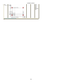
When using a Switch Matrix for Capacitance Measurements, it is physically not possible to eliminate all
stray capacitances up to the DUT. Therefore, you need to calibrate the instrument up to the switch matrix
with all matrix connections set to open. Calibration will remove the capacitance of the cables between CVmeter and switch matrix. To calibrate the way all to the DUT, for each matrix connection the capacitance
needs to be measured with the probe card in the "up" position (no DUTconnected). The measured
capacitances for every switch matrix connection will be removed from the measurements of the DUTs
capacitances.
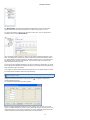
For automatic measurements, macros are available. These macros enable you to make
automatic series measurements of complete dies or arrays. They are created for
automatic measurements with or without heated chucks.
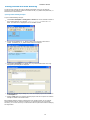
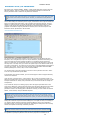
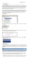
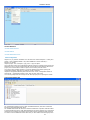
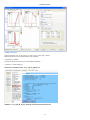
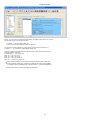
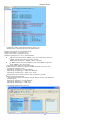
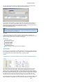
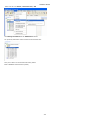
For example, open the IC-CAP model for BSIM3_DC_CV_Measure (from the IC-CAP/Main
window, right click the DC_CV_Measure model then select Edit). The Macros folder
contains a macro called Example_Wafer_Prober.
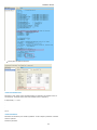
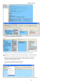
You will also find a macro in the
$ICCAP_ROOT/examples/model_files/mosfet/BSIM3/examples/waferprober directory
named prober_control.mdl. Please use this macro or model file and tailor it to your needs.
There are readme sections to explain the steps to be taken inside the macros.
The automatic measurement of model diagrams using the macro works without involving
the GUI.
For your convenience, the waferscan macro in the prober_control.mdl example model file
can be loaded into IC-CAP and can be run in a demo mode without taking actual
measurements.
Other DC/CV Measurement Module Folders
Notes (mosfet)
Temperature Setup (mosfet)
Device Definition (mosfet)
Options (mosfet)
Device Definition
The next step in the modeling process is to set up the measurement conditions for
different measurement tasks like DC, Capacitance, or Diode measurements and to enter
the devices to be used.
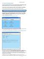
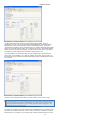
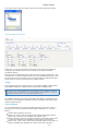
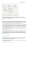
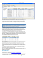
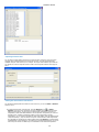
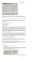
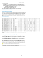
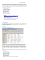
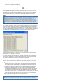
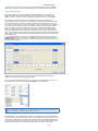
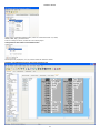
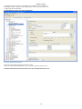
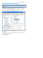
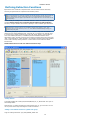
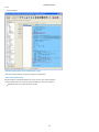
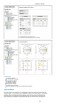
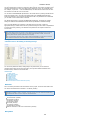
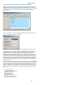
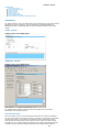
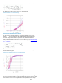
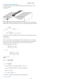
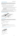
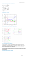
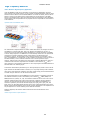
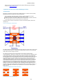
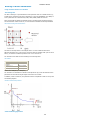
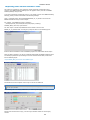
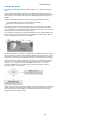
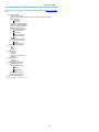
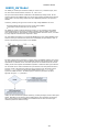
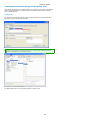
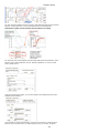
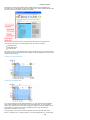
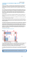
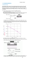
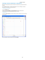
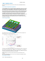
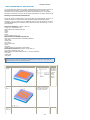
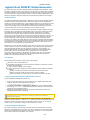
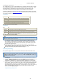
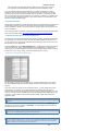
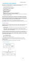
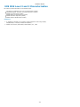
The Device Definition pane allows an easy setup of conditions for DC Transistor and
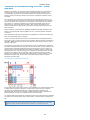
Capacitance as well as DC Diode measurements. The following figure shows the Device
Definition pane used for setting up measurement conditions as well as the devices to be
measured. You can use the icons or the menu to save this settings before proceeding to
the next task.
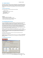
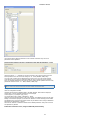
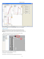
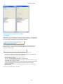
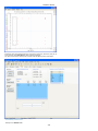
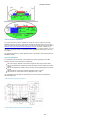
Device Definition Folder
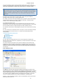
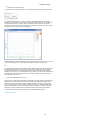
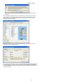
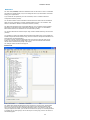
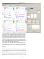
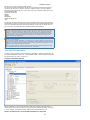
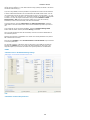
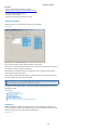
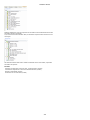
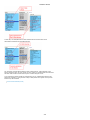
The Data tree on the left-side of the Device Definition pane displays the Data for this
measurement project. This tree definition can be different for different models. The above
figure shows the tree structure used for extracting BSIM3 device parameters. If you are
using the SOI Modeling Package, the Device Definition pane displays the entries which are
not normally present on BISM3/4, HSIM, or PSP measurement projects. For example,
there are no floating transistors to be measured in BSIM3 or 4 modeling tasks.
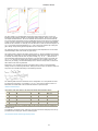
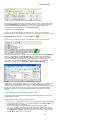
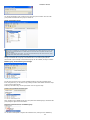
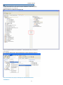
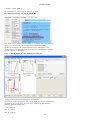
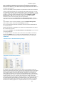
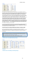
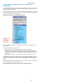
Click the + sign to expand the Transistor, Diode, and Capacitance entries and reveal the
Measurement and Device List.
16