1
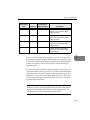
Software Architecture
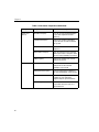
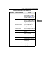
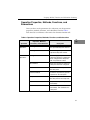
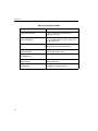
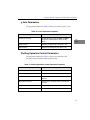
Channel-List
Entry
Channel
Synchronous
Digital I/O Value
0
7
1
Description
Sample channel 7 and output a
value of 1 to the dynamic digital
output channels.
1
5
1
Sample channel 5 and output a
value of 1 to the dynamic digital
output channels.
2
6
0
Sample channel 6 and output a
value of 0 to the dynamic digital
output channels.
3
4
0
Sample channel 4 and output a
value of 0 to the dynamic digital
output channels.
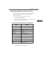
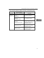
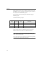
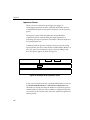
In this case, when channel 7 is sampled, a value of 1 is output to the
dynamic digital output channels. When channel 5 is sampled, a value
of 1 is output to the dynamic digital output channels. When channels
6 and 4 are sampled, a value of 0 is output to the dynamic digital
output channels.
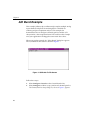
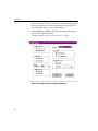
If your device had two dynamic digital output bits and a value of 1 is
output (01 in binary format), a value of 1 is written to dynamic digital
output bit 0 and a value of 0 is written to dynamic digital output bit 1.
Similarly, if a value of 2 is output (10 in binary format), a value of 0 is
written to dynamic digital output bit 0 and a value of 1 is written to
dynamic digital output bit 1.
5
5
5
5
5
5
5
5
Note: If you are controlling sample-and-hold devices with these
channels, you may need to program the first channel at the sample
logic level and the following channels at the hold logic level; see
your board/device driver documentation for details.
5
107