1
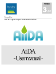
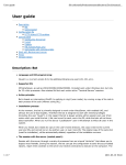
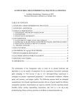
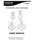
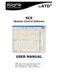
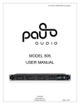
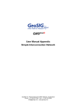
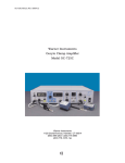
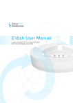
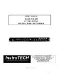
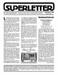
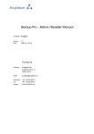
Manual 1.0 PIP 6 Pipette Puller HEKA Elektronik Dr. Schulze GmbH Wiesenstrasse 71 D-67466 Lambrecht/Pfalz Germany Phone Fax Web Site Email +49 (0) 6325 / 95 53-0 +49 (0) 6325 / 95 53-50 www.heka.com [email protected] [email protected] HEKA Electronics Inc. 47 Keddy Bridge Road R.R. #2 Mahone Bay, NS B0J 2E0 Canada Phone Fax Web Site Email +1 902 624 0606 +1 902 624 0310 www.heka.com [email protected] [email protected] HEKA Instruments Inc. 2128 Bellmore Avenue Bellmore, New York 11710-5606 USA Phone Fax Web Site Email +1 516 882-1155 +1 516 467-3125 www.heka.com [email protected] [email protected] Title Page: Temperature Controlled Pipette Puller PIP 6 © 2009 HEKA Elektronik Dr. Schulze GmbH COMPIP/2 Contents 1 Safety Guidelines 1 2 Introduction 3 2.1 Unpacking . . . . . . . . . . . . . . . . . . . . . . . . . . . . 3 2.2 Supplied Components . . . . . . . . . . . . . . . . . . . . . 3 2.3 Description . . . . . . . . . . . . . . . . . . . . . . . . . . . 4 2.4 Installation . . . . . . . . . . . . . . . . . . . . . . . . . . . 8 3 Operation 9 3.1 How to pull your pipettes . . . . . . . . . . . . . . . . . . . 9 3.2 How to select the right spacer disk . . . . . . . . . . . . . . 11 4 Adjustment of PIP 6 pipette puller 13 4.1 Adjustment of the heating filament . . . . . . . . . . . . . . 13 4.2 Adjustment of the pulling mechanism . . . . . . . . . . . . 14 4.3 Literature . . . . . . . . . . . . . . . . . . . . . . . . . . . . 17 1. Safety Guidelines Please read the instruction manual of the Pip 6 before taking the puller into operation to prevent any possible damage to life and equipment. In addition to the instruction manual of the Pip 6 puller, the regulations of prevention of accidents applicable to your country (VBG 4 in Germany) and the relevant rules for safety of the working environment are applicable. The instruction manual has been designed such that taking the Pip 6 pipette puller into operation is comprehensible, safe, economical and helps to prevent dangerous misuse. A safe use of the puller, minimal service costs and no delay in service can be guaranteed only if the instructions given in the operation manual are being followed. The instruction manual should always be in proximity to the puller. Misuse, neglected inspection of the instrument or disregarding operating instructions may endanger user/s or any third party and may cause damage to technical equipment. The Pip 6 pipette puller is manufactured according to currently applicable safety regulations. The puller is to be operated only if it is working properly. The puller should immediately be send for repair if any technical problem occurs which may endanger the safety of the user/s or any third party. The Pip 6 is only to be used for its intended purpose as described in the instruction manual. ”Intended purpose” includes regular inspection and service of the puller. It is possible to add technical equipment to the puller. This equipment is not defined as an ”instrument” according to European Community (EC) rules. Thus, equipment can only be added if it is labeled with the CEcertification and has an accompanying statement certifying conformity with EC-rules. Only technical equipment approved by HEKA can be added to the puller. Information concerning this matter will be provided on request by our service team. Any further use of the Pip 6 and added equipment, which does not fall within the ”intended purpose” of the puller, is not in accordance with the liability regulations. HEKA does not accept liability for any dam- 2 Safety Guidelines age caused by misuse of the Pip 6. Manipulations of the instrument are not permissible and lead to loss of liability by the manufacturer. Please contact HEKA before taking the Pip 6 puller into operation if you are uncertain regarding operating instructions, safety rules or the instruction manual in general. The Pip 6 instruction manual does not provide instructions for repair. Any necessary repair of the puller has to be done by certified specialists. HEKA offers such certified service. http://www.heka.com 2. Introduction 2.1 Unpacking After unpacking the Pip 6 and accessories from the shipping carton, please inspect each piece for any signs of shipping damage. Please contact the delivering carrier and HEKA immediately if there is any damage. Do not dispose of the shipping carton. The carrier will want to examine the shipping carton to process a damage claim. HEKA insures all shipments to cover shipping damage. It is also advisable to keep the shipping carton in the event that the instrument must be returned for service. 2.2 Supplied Components The following items should have been packed with your Pip 6 pipette puller: 1 Pip 6 pipette puller 1 power cord (110 or 220 Volt depending on application) 2 replacement fuses 1 printed user’s manual 3 spacer disks (#7, #9, #11) 1 package heating coils (10 pcs.) 1 adjustment block 1 hex-wrench (required for adjusting the pull mechanism) If any of these items are missing please contact HEKA or your dealer immediately. 4 Introduction 2.3 Description The Pip 6 is a temperature controlled puller which is a further step to make pulling of glass pipettes easier and more comfortable in the sense of a better reproducibility. It was developed for pulling glass pipettes as they are used for clamp experiments. The range of application of the produced pipettes covers e.g. intracellular recording pipettes or patchclamp pipettes. The pipettes are being produced by a 2-step vertical pull at different temperatures and pull lengths. Due to the symmetry of the pull you will always receive two equivalent pipettes. Special features: temperature controlled heating filaments high filament temperature range: 300˚ C - 1900˚ C precise temperature control providing a high reproducibility of pull procedures independent filament temperatures for first and second pull heating filament adjustable into two dimensions suitable for all types of soft and hard glass (except Quartz glass) of 1.0-3 mm diameter faster attained set temperature especially with the second pull http://www.heka.com 2.3 Description 5 Figure 2.1: PIP 6, front view 1 adjustable height lever 2 temperature settings display 3 plastic cover 4 temperature controller for the first pull 5 temperature controller for the second pull 6 power switch http://www.heka.com 6 Introduction 7 start button (for starting a pull) 8 temperature selection for first (A) and second pull (B). 9 fine adjustment for the height lever Figure 2.2: PIP 6, before first pull 10 tension screw 11 adjustment screws for the heating filament http://www.heka.com 2.3 Description 7 12 heating filament 13 spacer disk 14 adjusting wheel Figure 2.3: PIP 6, first pull http://www.heka.com 8 2.4 Introduction Installation Connect the power cord to the Pip 6. The internal power supply used in the Pip 6 is an auto switching multi-voltage supply that will operate from 90 Volts to 250 Volts. Make sure that the Pip 6 power cord is plugged into a properly grounded AC receptacle. Improper grounding of the Pip 6 could result in an electrical shock hazard. It is advisable to plug all equipment into a common outlet strip. This will minimize power line induced noise in the system. After switching on the Pip 6, the puller is ready to use. http://www.heka.com 3. Operation Two pipettes are being pulled from a glass capillary. The shape of the pipette tip is determined by the temperature of the first and second pulls, the type of spacer disk being used and the type of capillary glass being used. Usually the tips have a diameter of 1-2µm. In the following, the steps needed to pull pipettes with the Pip 6 are described. Also some examples of typical pipettes are given. 3.1 How to pull your pipettes 1. The plastic cover should be opened and lowered away from the pulling mechanism. 2. Insert the glass capillary into the guidance. Before tightening the upper tension screw, the silver height lever should be brought forward and the top of capillary should be at the same height as the lever. Note: The height of the lever should be adjusted so the final length of the two pulled pipettes are the same. It may take a few pulls before this height setting is exact for your particular length of glass. If, for example, you find that the top pipette is longer than the bottom, then the height lever should be lowered accordingly. The lever can be adjusted either up or down by turning the gold screw at the bottom of the lever mechanism. 3. Move the pull mechanism to its most upper position and fix the lower end of the glass capillary by tightening the lower tension screw. 4. Fit your spacer disk of choice onto the guide shaft and turn the disk counterclockwise until stop position. 10 Operation 5. Raise the plastic cover and close it back in front of the pulling mechanism. 6. For the first pull, select the desired heating filament temperature at potentiometer A, put the temperature selection switch to position A and press the Start button. 7. The heating filament will start to glow and melt the glass capillary. As the capillary is being heated, it will be pulled by gravity. At the end of this and every pull, the heating filament will be switched-off automatically. 8. After the filament has stopped glowing, the plastic cover should be opened and lowered away from the pulling mechanism. 9. Loosen the upper tension screw, lift the pull mechanism to its most upper position, turn the spacer disk clockwise until stop position and lower the pull mechanism until it sits on the spacer disk. 10. Tighten the upper tension screw and turn the spacer disk to the middle position. 11. Raise the plastic cover and close it in front of the pulling mechanism. 12. To start the second pull, set the desired heating filament temperature at potentiometer B, put the temperature selection switch to position B and press the Start button. 13. With the second pull, the glass capillary will break and two pipettes with identical tips are produced. 14. Open the plastic cover and lower it away from the pulling mechanism. 15. Loosen the upper and lower tension screws and remove the upper and lower pipettes. Note: It is recommended to turn on the puller about 30 minutes before use since reproducibility cannot be guaranteed during the warm-up period. http://www.heka.com 3.2 How to select the right spacer disk disk number 7 9 11 3.2 A (mm) 9.0 7.0 5.0 B(mm) 13.5 12.8 12.0 11 1st pull length (mm) 7.0 9.0 11.0 How to select the right spacer disk The shape of the pipette is amongst others determined by the length of the first and second pull. For that reason our delivery volume includes three spacers disks which allow the pull of different types of pipettes (see figure 3.1). The disk number determines the length of the first pull (16mm-A, see: Adjustment of the pulling mechanism). Distance B serves for identical tips. Figure 3.1: Spacer disk with distances A and B With a first long pull (disk# 11) you will receive pipettes with long thin tips. Short tips with a low electrical resistance will be received with short pull lengths e.g. with disk # 7. http://www.heka.com 12 http://www.heka.com Operation 4. Adjustment of PIP 6 pipette puller The pulling mechanism is preset before delivery. In case there will be a change of settings (e.g. an exchange of the heating filament) the pulling mechanism and the heating filament can be easily adjusted by yourselves. 4.1 Adjustment of the heating filament Insert a heating filament into the filament receptor, however do not tighten the tension screws (lower side of the support). Push the glass tube through the heating filament and tighten it by means of the tension screws. Turn the heating filament into horizontal position and fix it (lower side of the support). Adjust the heating filament with the adjustment screws in such a way that the glass tube will be in centric position (screws at front side of the support resp. thumb-wheel left of the support). 14 Adjustment of PIP 6 pipette puller 4.2 Adjustment of the pulling mechanism For adjustment please use the adjustment block (16 mm) as well as the hexagon wrench which is included with the delivery. 1. Switch-off the puller 2. Remove the lower cover by loosening the two screws. 3. Adjust the vertical movement of the pulling mechanism to 16 mm by means of screw 1 (figure 4.3). Please use the 16 mm adjustment block for that purpose (figure 4.1). Move the lower part of the pulling mechanism to its top most position and fix screw 1 again. Figure 4.1: Pulling Mechanism (upper part) 4. Adjust the right gear bar according figure 4.2 by using screw 2 (figure 4.3). (The pulling mechanism must be at lowest position.) http://www.heka.com 4.2 Adjustment of the pulling mechanism 15 Figure 4.2: Pulling Mechanism (lower part) Figure 4.3: Adjustment screws 1 and 2 http://www.heka.com 16 Adjustment of PIP 6 pipette puller 5. By means of screw 3 (figure 4.4) adjust the left gear bar in such a way that it will operate the limit switch as per (figure 4.2). (The pulling mechanism is at lowest position). Figure 4.4: Adjustment screw 3 6. Mount the lower cover. http://www.heka.com 4.3 Literature 4.3 17 Literature The technique of pulling glass pipettes is described in the following articles: B. Sakmann and E. Neher: Geometric parameters of pipettes and membrane patches. In: Single-Channel Recording (B. Sakman and E. Neher, eds), Plenum Press, New York Hamill, O.P., Marty, A., Neher, E., Sakmann, B. & Sigworth, F.J. (1981) Improved patch clamp techniques for high-resolution current recording from cells and cell-free membrane patches. Pflügers Arch. 391, 85-100. Rae, J. & Levis, R. (1984) Patch clamp recordings from the epithelium of the lens obtained using glasses selected for low noise and improved sealing properties. Biophys. J. 45, 144-146. http://www.heka.com