1
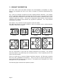
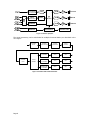
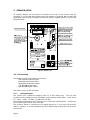
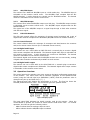
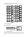
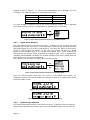
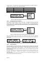
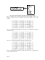
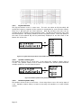
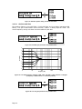
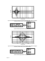
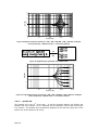
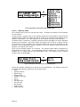
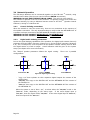
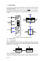
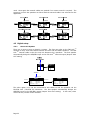
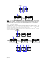
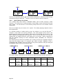
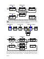
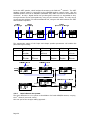
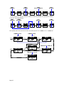
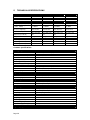
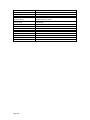
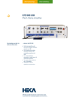
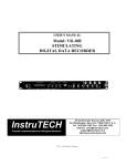
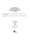
Active Monitor
PROFESSIONAL AUDIO MONITORING
AV30.D
AV40.D
USER MANUAL
Page 2
TABLE OF CONTENT
1
2
3
4
5
INTRODUCTION ............................................................................................... 6
1.1
This Manual ............................................................................................. 6
1.2
The Product Concept................................................................................. 6
1.3
Digital Precision ....................................................................................... 6
PRODUCT DESCRIPTION ................................................................................... 7
SPEAKER SETUP .............................................................................................. 9
3.1
Connectivity ............................................................................................ 9
3.1.1 Analogue Input ..................................................................................... 9
3.1.2 AES/EBU Input ....................................................................................10
3.1.3 AES/EBU Output ..................................................................................10
3.1.4 FAR Link Network ................................................................................10
3.2
Operation Overview .................................................................................10
3.3
Parameter definition ................................................................................11
3.3.1 Speaker Volume ..................................................................................11
3.3.2 Digital Channel Selection ......................................................................11
3.3.3 Signal Input Selection ..........................................................................12
3.3.4 Digital Output Selection ........................................................................12
3.3.5 Analogue Full scale selection .................................................................13
3.3.6 Curve selection....................................................................................13
3.3.7 EQ Set selection ..................................................................................15
3.3.8 Speaker relative level ...........................................................................15
3.3.9 Relative speaker delay..........................................................................15
3.3.10
Shelves and Tilts ..............................................................................16
3.3.11
Speaker ID ......................................................................................18
3.3.12
Network mode .................................................................................19
3.4
Network Operation ..................................................................................20
3.4.1 Control chaining constraints ..................................................................20
3.4.2 Digital audio chaining constraints...........................................................20
SYSTEM SETUP ...............................................................................................21
4.1
Analogue Setup ......................................................................................21
4.1.1 Stereo System.....................................................................................21
4.1.2 Multi-channel 5.1 System .....................................................................21
4.2
Digital setup ...........................................................................................22
4.2.1 Stereo 2.0 System ...............................................................................22
4.2.2 Stereo 2.1 System ...............................................................................23
4.2.3 Multi-channel 5.1 System .....................................................................24
4.2.4 Multi-channel 6.1 System .....................................................................26
TECHNICAL SPECIFICATIONS ...........................................................................28
Page 3
REVISION HISTORY
Date
Version
Author
Change
2011-02-12
1.0
X. Lambrecht
Initial revision
PRODUCT COMPLIANCE
The AV20 monitors comply with the following specifications:
- EN 55103-1:
- EN 55103-2:
- EN 55022:
- EN 60065:
- 89/336/EEC
Page 4
Product family standard for audio, video, audio-visual and
entertainment apparatus for professional use – Part 1: Emission
Product family standard for audio, video, audio-visual and
entertainment apparatus for professional use – Part 2: Immunity
Information technology equipment. Radio disturbance characteristics.
Limits and methods of measurement (Class B)
Safety requirements for main operated electronics and related
apparatus for household and similar general use.
European Directive on electromagnetic compatibility (harmonized
standard)
SAFETY INSTRUCTIONS
1.
2.
3.
4.
5.
6.
7.
8.
9.
10.
11.
12.
13.
Read these instructions.
Keep these instructions.
Heed all warnings.
Follow all instructions.
Do not use this apparatus near water.
Clean only with a dry cloth.
Do not block any ventilation openings. Install in accordance with the manufacturer's instructions.
Do not install near any heat sources such as radiators, heat registers, stoves, or other apparatus
(including amplifiers) that produce heat.
Protect the power cord from being walked on or pinched particularly at plugs, convenience
receptacles, and the point where they exit from the apparatus.
Only use attachments/accessories specified by the manufacturer.
Use only with the cart, stand, tripod, bracket, or table specified by the manufacturer, or sold with
the apparatus. When a cart is used, use caution when moving the cart/apparatus combination to
avoid injury from tip-over.
Unplug this apparatus during lightning storms or when unused for long periods of time.
Refer all servicing to qualified service personnel. Servicing is required when the apparatus has
been damaged in any way, such as power supply cord or plug is damaged, liquid has been spilled
or objects have fallen into the apparatus, the apparatus has been exposed to rain or moisture,
does not operate normally, or has been dropped.
..Warning!..
• To reduce the risk of fire or electrical shock, do not expose this equipment to dripping or splashing
and ensure that no objects filled with liquids, such as vases, are placed on the equipment.
• Use a three wire grounding type line cord like the one supplied with the product.
• This equipment should be installed near the socket outlet and disconnection of the device should
be easily accessible.
• To completely disconnect from AC mains, disconnect the power supply cord from the AC
receptacle.
• The mains plug of the power supply shall remain readily operable.
• Do not install in a confined space.
• Do not open the unit - risk of electric shock inside.
..Service..
There are no user-serviceable parts inside. All service must be performed by qualified personnel.
Page 5
1
INTRODUCTION
1.1 This Manual
The latest manual revision is always available for download from www.atd2.com. Please
compare to the revision number of the manual (see page 4) available for download from
our web-site and download if newer. The present document will describe how to connect
and setup a speaker system.
1.2 The Product Concept
The FAR Active monitor systems take a quantum leap forward in near-field / mid-field
monitoring and ATD2 is very proud to present these systems. The AV series include high
quality analogue Class D amplification with the addition of powerful DSPs and CPU. New
possibilities are opened for easy, convenient and central control of both audio and setupinfo via dedicated PC software and remote control. The networking possibilities will fit
nicely into today's applications and can be taken far into the future studio.
Unlike many rear ported monitors that can be very unpractical to set up, the 3 ways AV
series feature sealed box bass principle design that allows flush mounting, easy
placement in the room and very accurate bass/medium reproduction.
The 3 ways AV monitors are Pro Audio mid-field monitors and are excellent for stereo
and surround setups in applications such as Music Recording/Mixing, Post production,
Film, Broadcast, Video-editing etc.
1.3 Digital Precision
The frequency response and timing of the woofer, medium and tweeter signals (gain and
delay) of the 3 ways AV monitors is controlled to a level of precision only practically
obtainable with DSP.
All the filters available in the speaker are implemented in the digital domain. This
guarantees a perfect repeatability from speaker to speaker. They will never vary with
temperature, humidity and aging. It cannot be made more accurate and stable.
The monitor impulse response has been optimized to guarantee the best possible
dynamics and accuracy.
As most productions do end up in a digital format these days, the FAR Active monitors
allow direct monitoring of the digital signal. Simply feed the monitors directly with an
AES/EBU signal (IEC60958 compliant).
However, as many studios are today still working with analogue signals for monitoring,
all the FAR Active monitors have, as standard feature, a very high quality analogue input.
Page 6
2
PRODUCT DESCRIPTION
The AV10, AV20, AV30 and AV40 monitors are multi-amplified (3 amplifiers in total).
There is one amplifier per driver unit. Refer to chapter 5 [Technical Specifications] for
details.
The 3 ways AV monitors all feature the same medium/tweeter assembly. The medium
driver is optimally loaded and the acoustic load is built in such a way that there cannot
be any destructive interference at the back side of the medium membrane due to wave
reflection inside the volume. This type of construction helps having a flat frequency
response of the medium driver without any significant equalization. It’s a step towards
sound purity and clarity.
This allows a very consistent sound signature across all models.
The plate being square, it is also possible to order the speakers with a medium/tweeter
assembly rotated by 90 degrees.
AV10.D-HL
AV30.D-HL
AV10.D-HR
AV30.D-HR
AV20.D-HL
AV40.D-HL
AV20.D-HR
AV40.D-HR
The box construction is such that the internal resonances are minimal. The internal
structure makes it very stiff though not excessively heavy. This is especially true for the
AV10 and AV20 models.
There is no also such a concept of Master and Slave monitors. All FAR Active monitors
have the same capabilities and features. There are also no special requirements on
power ON and OFF sequences of the monitors. The speakers were designed to be “clicks
and plops” free, in any conditions.
The following figure describes the speaker synoptic.
Page 7
Figure 1: Monitor Synoptic
The signal processing can be subdivided in multiple functional blocks, as described in the
next figure.
SPEAKER
DELAY
SPEAKER
LEVEL
3 WAY
XOVER
SPEAKER
EQUALIZATION
10 BAND
EQUALIZER
CURVE
FILTERS
DRIVER TIME
ALIGNMENT
GAIN
DRC
DRIVER TIME
ALIGNMENT
GAIN
DRC
DRIVER TIME
ALIGNMENT
GAIN
DRC
Figure 2: Monitor DSP Functional blocks
Page 8
3
SPEAKER SETUP
IN
OUT
DIGITAL IN
POWER
DIGITAL OUT
PUSH
NETWORK
PUSH
ANALOG IN
All controls, display and connectors are located at the rear of the monitor with the
exception of a front LED that indicates when the speaker is powered ON and that also
signal with various types of blinking the network activity, amplifier limiter in service and
hardware faults.
Figure 3: Monitor rear
3.1 Connectivity
The speaker provides the following connectors:
- XLR Analogue balanced input
- RJ45 FAR Link Network input
- RJ45 FAR Link Network output
- XLR AES/EBU digital input
- XLR AES/EBU digital output
The power input is an IEC connector.
3.1.1
Analogue Input
The monitor has a balanced analogue input on a XLR combo plug. The full scale
sensitivity of the analogue input is selectable via the monitor control menu. It can be set
to +3 dBu, +9 dBu, +15 dBu, +21 dBu and +24 dBu.
The standard broadcast full scale input level is +6 dBu with 9 dB headroom. In this case,
the full scale input shall be set to +15 dBu.
The analogue signal is converted to the digital domain by a very high-end converter
(96kHz – 24 bits). It is then treated as the other digital audio streams that can be fed to
the monitor.
Page 9
3.1.2
AES/EBU Input
The monitor has a balanced AES/EBU input on a XLR combo plug. The AES/EBU input is
selectable via the monitor control menu. The AES/EBU input complies with the IEC
60958 standard. 2 audio channels are carried over an IEC60958 stream. The desired
channel is selectable via the monitor control menu.
3.1.3
AES/EBU Output
The monitor has a balanced AES/EBU output on a XLR plug. The AES/EBU output content
is selectable via the monitor control menu. The AES/EBU output complies with the IEC
60958 standard.
The typical use of the AES/EBU output is a signal loop-through to feed other monitors
with the same signal.
3.1.4
FAR Link Network
The FAR Link network allows for streaming of monitor control messages and a pair of
digital audio channels compliant with IEC60958 (AES/EBU like but on another medium).
3.1.4.1 Control Channel
The control channel allows the exchange of messages and data between the monitors
and/or the remote control devices (PC or dedicated remote control).
3.1.4.2 Digital audio input
The monitor can use a CAT5 cable on RJ45 FAR Link TM network plug to receive a digital
audio stream compliant with IEC60958. The Network digital audio input is selectable via
the monitor control menu. 2 audio channels are carried over IEC60958. The desired
channel is selectable via the monitor control menu.
The Network digital audio stream and the AES/EBU stream can run concurrently, making
4 digital audio channels simultaneously available to each monitor.
3.1.4.3 Digital audio output
The monitor can use a CTA5 cable on the RJ45 FAR Link TM network plug to transmit a
digital audio stream compliant with IEC60958. The Network digital audio output content
is selectable via the monitor control menu.
3.2 Operation Overview
The control panel at the speaker rear gives access to the basic configuration parameters
of the monitor. The menu items can be selected (displayed on the alphanumerical
screen) using the left and right keys (PREVIOUS / NEXT) while the parameter value is
changed using the up and down keys (+ / -).
The alphanumerical LCD displays the information on 2 lines. The first line shows the
selected parameter and its value. The second line gives the speaker status.
Figure 4: Display layout
The input signal field indicates the signal currently used by the monitor. When the
central button is pushed, the monitor is muted and the field shows “Mut”. In nominal
operation, the field can get the following values:
- ANA to indicate that the analogue input is active
- AES to indicate that the AES/EBU input is selected
Page 10
- NET to indicate that the FAR Link network is the signal source
The following picture shows the various speaker parameters accessible via the control
panel and their associated value range.
Figure 5: Monitor Setup Parameter Overview
3.3 Parameter definition
3.3.1
Speaker Volume
The speaker volume is the first menu item. It can range from -40dB to +20 dB by steps
of 0.5 dB.
Figure 6: Volume parameter and values
3.3.2
Digital Channel Selection
The digital channel selector is the second menu item. It allows the user to select the first
channel (A) or second channel (B) of a IEC60958 digital audio stream. In stereo
applications, the left channel is mapped on the A channel and the right channel is
Page 11
mapped on the B channel. In multi-channel applications, three AES/EBU links are
necessary. The channel mapping is usually defined as follow:
AES/EBU Link
Cable 1
Cable 2
Cable 3
Channel A
Left
Center
Surround left
Channel B
Right
LFE
Surround right
It is also possible to select the sum of the A and B channels (A+B). This is especially
useful when having a stereo 2.1 configuration (2 speakers plus 1 subwoofer).
Figure 7: Digital channel selection parameter and possible values
3.3.3
Signal Input Selection
The input signal selector is the third menu item. It allows the user to select the input
signal that the monitor will render. As the FAR Active monitor works with both analogue
and digital signals, the user must set a preference. The “Auto Sel” option let the monitor
decide on what to select by default. In this case, the monitor will look for a digital
stream on the AES/EBU input or on the FAR Link network input. While scanning the
digital inputs, the monitor render by default the analogue input. Once a digital stream
compliant with IEC60958 is detected, the monitor switches to the active digital input and
stays locked to it till the stream disappears.
The monitor input can also be forced to one of the three inputs.
Figure 8: Input signal selection parameter and possible values
When the selected digital input does not receive a valid digital audio stream, the
separation symbol of the second display line changes its form to an empty square frame
instead of a plain square.
Figure 9: AES input with valid IEC60958 stream
Figure 10: AES input with invalid or not present signal
3.3.4
Digital Output Selection
The digital output signal selector is the forth menu item. It allows the user to select the
digital output signal that the monitor will send on the AES/EBU output and the FAR Link
Page 12
network output. The monitor can route the digital input signals to the digital outputs in
multiple ways (see section 3.4 for additional details).
Digital output
Copy I/O
AES/EBU
NETwork
Auto Sel
AES/EBU output
AES/EBU input
AES/EBU input
FAR Link network input
Active digital input
FAR Link network output
FAR Link network input
AES/EBU input
FAR Link network input
Active digital input
Figure 11: Digital output signal selection parameter and possible values
3.3.5
Analogue Full scale selection
The Analogue full scale selector is the 5th menu item. The balanced input full scale level
can be set to +3 dBu, +9 dBu, +15 dBu, +21 dBu or +24 dBu. It is assumed that the
signal is delivered in a symmetrical fashion to the speaker. If an asymmetrical signal or
an unbalanced signal must be used, the effective full scale level will become the one
displayed minus 6 dB.
Figure 12: Analogue input full scale selection parameter and possible values
When the analogue input level exceeds the selected full scale level, the separation
symbol of the second display line changes its form to an empty square frame instead of a
plain square.
Figure 13: Display behavior when the analogue input level exceeds the selected full scale level
3.3.6
Curve selection
The Curve selector is the 6th menu item. The user can select a preset curve which will
modify the frequency response of the monitor to emulate a given acoustical environment.
There are 7 presets plus the FLAT reference. Each preset filters and name can be
modified by the PC Speaker Control Software (SCS). The Curve selector does only recall
the stored preset.
The factory settings of the monitor provide 4 defined curves by default (Academy, Car,
TV, Club). The “Custom1”, “Custom2” and “Custom3” curves are equivalent to the FLAT
reference curve.
The 4 first letters of the name of the selected curve are permanently displayed on the
second field of the bottom line of the LCD.
Page 13
Figure 14: Curve selection parameter and possible values (factory default shown)
The curve “Academy” has a low pass filter of the first order (6 dB/Oct) at 8 kHz. It is
meant to emulate the effect of a perforated cinema screen placed in front of the
speakers.
The curve CAR simulates the listening in a car environment. A 4 dB boost at 50 Hz and a
2 dB boost at 3 kHz.
The curve “TV” simulates the frequency response of a standard TV set.
The curve CLUB simulates the listening in a night club environment. A 2 dB boost at 60
Hz and a 5 dB boost at 3 kHz.
Page 14
3.3.7
EQ Set selection
The EQ Set selector is the 7th menu item. The user can select an EQ Set which will
modify the frequency response of the monitor to compensate for room acoustics effects.
There are 7 QE Sets plus the FLAT reference. Each EQ set filters and name can be
modified by the PC Speaker Control Software (SCS). The EQ Set selector does only recall
the stored preset. The factory default for all the 7 EQ Sets is FLAT. The 4 first letters of
the name of the selected EQ set are permanently displayed on the third field of the
bottom line of the LCD.
Figure 15: EQ Set selection parameter and possible values (factory default shown)
3.3.8
Speaker relative level
The speaker volume is the 8th menu item. It can range from -10dB to 0 dB by steps of
0.5 dB. The speaker relative level is meant to balance the acoustic power between
multiple speakers in a multi-channel system.
Figure 16: Relative speaker level parameter and values
3.3.9
Relative speaker delay
The speaker volume is the 9th menu item. It can range from 0 cm to 150 cm by steps of
5 cm. Speakers relative delay is meant to time align the speakers in a multi-channel
system.
Page 15
Figure 17: Relative speaker delay parameter and values
3.3.10
Shelves and Tilts
The speaker features a low shelf filter, a high shelf filter and 3 tilt filters (parametric EQ
filters). The gain of these filters can be set from -3 dB to +3 dB by steps of 0.5 dB. The
corner frequency and Q or S factor can be modified by the SCS.
Figure 18: Low Shelf gain parameter and possible value
4
3
Gain (dB)
2
1
0
-1
-2
-3
-4
10
100
1000
Frequency (Hz)
10000
100000
Figure 19: Low Shelf frequency response -3dB, -2dB, -1dB, 0dB, +1dB, +2dB and +3 dB gain
(Frequency = 300 Hz and S = 1 are factory default)
Figure 20: Low Tilt gain parameter and possible value
Page 16
4
3
Gain (dB)
2
1
0
-1
-2
-3
-4
10
100
1000
10000
100000
Frequency (Hz)
Figure 21: Low tilt frequency response for -3dB, -2dB, -1dB, 0dB, +1dB, +2dB and +3 dB gain
(Frequency = 60 Hz and Q = 1.5 are factory default)
Figure 22: Mid Tilt gain parameter and possible value
4
3
Gain (dB)
2
1
0
-1
-2
-3
-4
10
100
1000
10000
100000
Frequency (Hz)
Figure 23: Mid tilt frequency response for -3dB, -2dB, -1dB, 0dB, +1dB, +2dB and +3 dB gain
(Frequency = 800 Hz and Q = 0.4 are factory default)
Figure 24: Mid Tilt gain parameter and possible value
Page 17
4
3
Gain (dB)
2
1
0
-1
-2
-3
-4
10
100
1000
10000
100000
Frequency (Hz)
Figure 25: High tilt frequency response for -3dB, -2dB, -1dB, 0dB, +1dB, +2dB and +3 dB gain
values (Frequency = 9500 Hz and Q = 1.2 are factory default)
Figure 26: High Shelf gain parameter and possible value
4
3
Gain (dB)
2
1
0
-1
-2
-3
-4
10
100
1000
Frequency (Hz)
10000
100000
Figure 27: High Shelf frequency response for -3dB, -2dB, -1dB, 0dB, +1dB, +2dB and +3 dB gain
values (Frequency = 4000 Hz and S = 1 are factory default)
3.3.11
Speaker ID
The speaker ID is the 15th menu item. It sets the network address and defines the
speaker role in the system. Up to 7 speakers and 2 subwoofers can be used concurrently
in a network. The speaker ID is permanently displayed in the last field (right end) of the
bottom line of the speaker LCD screen.
Page 18
Figure 28: Speaker ID parameter and possible value
3.3.12
Network mode
The network mode is the 16th and last menu item. It defines the behavior of the speaker
on the network.
In Slave mode, a change made on the speaker parameter via the speaker control panel is
reflected on the network to allow the remote control or the SCS to keep updated on the
speaker configuration. The other speakers on the network will ignore these changes.
In Master mode, a change on a speaker parameter will be propagated on all the speakers
present on the network. This mode allows one speaker to be used as a remote control.
For instance, muting a speaker set in network master will mute all the speakers in the
network. When a parameter shall be changed on only one speaker, make sure that the
speaker is in network slave mode.
There can be multiple masters in a network. The network mode status is displayed on
the bottom line of the screen. It is concatenated with the speaker ID. For instance, the
speaker ID 1 in network slave mode will display a S1. The speaker ID2 in network
master mode will display M2.
Figure 29: Network mode parameter and possible value
Not all the speaker parameters are allowed to be broadcasted. The following list gives
the parameters that are affected by the network mode.
• Mute
• Speaker Volume
• Signal Input
• Digital output
• Analogue full scale
• Curve
• EQ set
• Low Shelf gain
• Low Tilt gain
• Mid Tilt gain
• High Tilt gain
• High Shelf gain
Page 19
3.4 Network Operation
The FAR Active Monitors can be connected together via the FAR Link TM network, using
standard CAT5 cables (like the ones used in Ethernet PATCH connections).
WARNING: DO NOT USE ETHERNET CROSS CABLE. They will not work properly.
The network is optional in the use of the monitors. Its primary purpose is to control the
speakers remotely, by using a dedicated remote control or the SCS TM (Speaker Control
Software) running on a Windows OS.
3.4.1
Control chaining constraints
When the network is used for control only, there are no constraints in the sequence of
the speaker connection. The only important thing to verify is that the NETWORK OUT of
a speaker is always connected to the NETWORK IN of another speaker.
WARNING: DO NOT CONNECT NETWORK OUT TO NETWORK OUT.
WARNING: DO NOT CONNECT NETWORK IN TO NETWORK IN.
3.4.2
Digital audio chaining constraints
Due to the signal bridging capabilities of the speakers, the digital audio stream does only
propagate from the INPUT connector (whatever it is) to the OUTPUT connector (whatever
it is). As a consequence, some sequences in the speaker network chaining will not allow
the digital stream to reach its target. Careful attention shall be given to the system
setup (see chapter 4 for more information).
The “Output” speaker parameter defines the signal routing.
configurations.
There are 3 possible
Figure 30: Digital signal routing
-
“Copy I/O” does replicate on their respective digital outputs the content of the
digital inputs
“AES/EBU” does copy on the DIGITAL OUT and the NETWORK OUT the content of
the DIGITAL IN
“NETwork” does copy on the DIGITAL OUT and the NETWORK OUT the content of
the NETWORK IN.
When the system is set to “Auto Sel”, it selects either the “AES/EBU” mode or the
“NETwork” mode, depending on the active input. If the active digital input is
“AES/EBU”, then the output will be “AES/EBU”. If the active digital input is “NETwork”,
then the output will be “NETwork”.
Page 20
4
SYSTEM SETUP
DIGITAL OUT
PUSH
DIGITAL IN
OUT
NETWORK
IN
PUSH
ANALOG IN
In this chapter, the speaker will be represented by a box showing the speaker function
with the required speaker parameter values and a box showing, for the same speaker,
the digital signal routing.
For instance, the following speaker representation is the .LEFT. one in the system. It
has its speaker ID configured with the value “1.FRONT LEFT”, its input set to “AES/EBU”,
its digital output set to “AES/EBU” and its digital channel selection set to “A(L)” – left
channel.
Figure 31: Speaker connectivity and cabling representation
4.1 Analogue Setup
4.1.1
Stereo System
This is the easiest setup. The two speakers are fed with balanced analogue signals. Only
the speaker analogue input is used. The network cable is optional and is only used for
speaker control. If no remote control of the speakers is desired, the network inputs and
outputs can be left unconnected.
ANALOGUE (LEFT)
ANALOGUE (RIGHT)
ANALOGUE IN
ANALOGUE IN
LEFT
NETWORK IN
4.1.2
ID:
Input:
Output:
Digital Ch.:
1. FRONT LEFT
Auto Sel
Auto Sel
A(L)
RIGHT
NETWORK OUT
NETWORK IN
ID:
Input:
Output:
Digital Ch.:
2. FRONT RIGHT
Auto Sel
Auto Sel
B(R)
Multi-channel 5.1 System
As for the stereo setup, an analogue 5.1 system is quite simple to install. The six
speakers are fed with balanced analogue signals. Only the speaker analogue input is
Page 21
used. Once again the network cables are optional if no remote control is required. The
sequence in which the speakers are linked with the network cable is not relevant for this
application.
4.2 Digital setup
4.2.1
Stereo 2.0 System
There are 2 ways to setup a digital 2.0 system. The first one relies on the FAR Link TM
network to carry audio and control between the LEFT and the RIGHT speakers. The FAR
Link TM network cable is then the only link between the 2 speakers. The first speaker
automatically bridge the AES/EBU input to the FAR Link TM network output (Output “Auto
Sel” setting)
AES/EBU
DIGITAL IN
LEFT
NETWORK IN
ID:
Input:
Output:
Digital Ch.:
1. FRONT LEFT
Auto Sel
Auto Sel
A(L)
RIGHT
NETWORK OUT
NETWORK IN
ID:
Input:
Output:
Digital Ch.:
2. FRONT RIGHT
Auto Sel
Auto Sel
B(R)
The other option is to use the conventional XLR cables to link the speakers via the
DIGITAL OUT / DIGITAL IN connectors. The first speaker automatically bridges the
AES/EBU input to the AES/EBU output (Output “Auto Sel” setting) In this case, there
will not be any remote control enabled.
Page 22
AES/EBU
(LEFT & RIGHT)
LEFT
RIGHT
Note: It is not useful to have both the XLR cables and the network cable in place
between two speakers. The quality of the digital audio link provided by the FAR Link TM
network is at least as good as the one of a classical AES/EBU output on XLR connector.
4.2.2
Stereo 2.1 System
A subwoofer can be used to improve the bass extension of a stereo system. The
subwoofer will use the sum of the left and right channels present in the IEC60958
streams. The subwoofer digital channel selection shall be “A+B”.
As for the classical stereo setup, the system can be cabled using the FAR Link TM network
or just the standard XLR cables.
AES/EBU
(LEFT & RIGHT)
LEFT
Page 23
RIGHT
SUB
However, for practical reasons and future system maintenance easiness, we do strongly
recommend using the FAR Link TM network, even if no remote control is required.
4.2.3
Multi-channel 5.1 System
A 5.1 digital setup does require 3 AES/EBU cables, each of them carrying 2 audio
channels. The channels are usually grouped in Left & Right, Center & LFE and Surround
Left & Right. We will assume in the following setups that this is the default channel
assignment.
There are multiple ways to connect a 5.1 system. The cabling topology depends a bit on
the requirements.
If a minimal number of cables shall be used, the solution is to use the FAR Link TM
network to carry audio and control messages. The audio streams will be sent to the
speakers by the mean of 3 XLR cables, connected to the DIGITAL IN connector of the
LEFT, CENTER and SURROUND LEFT speakers. As we use the FAR Link TM to carry the
digital audio, the cabling sequence does matter but is not unique. What is important is
that the speakers sharing the same IEC60958 stream (AES/EBU) are contiguous,
network wise.
The following Figure shows one possible way to easily connect the 6 speakers together.
Note that the cabling order of a speaker pair (LEFT & RIGHT, CENTER & LFE or
SURROUND LEFT & RIGHT) does not matter, as long as the speaker of the pair that gets
the AES/EBU cable is first in the network chain.
The signal routing is achieved by the mean of the Input and Output speaker parameters.
Input
Output
Page 24
LEFT
Auto Sel
or
AES/EBU
Auto Sel
or
AES/EBU
RIGHT
Auto Sel
or
NETwork
Auto Sel
or
NETwork
CENTER
AES/EBU
Auto Sel
or
AES/EBU
LFE
Auto Sel
or
NETwork
Auto Sel
or
NETwork
SUR L
AES/EBU
Auto Sel
or
AES/EBU
SUR R
Auto Sel
or
NETwork
Auto Sel
or
NETwork
Note: If a second subwoofer for the LFE channel is required, it can simply be inserted
right before or after the first subwoofer. The second subwoofer will copy all the settings
of the first subwoofer but the spear ID that shall be “9.SUBWOOFER 2”.
If the proper sequence cannot be respected because the main cabling requirement is to
have a speaker linked to its closest neighbor in the room, some speakers will not get the
appropriate audio channel through the network. The AES/EBU (LEFT & RIGHT) signal is
Page 25
fed to the LEFT speaker, which bridges the stream to the FAR Link TM network. The LEFT
speaker network output is connected to the CENTER speaker network input. But the
CENTER speaker also has an AES/EBU (CENTER & LFE) cable connected to its DIGITAL IN
connector. As only 1 digital stream can go through the network, it is impossible to carry
the right channel to the right speaker by using only the network cables. The only way to
circumvent the problem is to add an additional link, using an XLR cable between the LEFT
and the RIGHT speakers.
The appropriate setting of the Input and Output speaker parameters will enable this
particular signal routing.
Input
Output
4.2.4
LEFT
Auto Sel
or
AES/EBU
Auto Sel
or
AES/EBU
CENTER
AES/EBU
Auto Sel
or
NETwork
LFE
Auto Sel
or
NETwork
Auto Sel
RIGHT
AES/EBU
SUR R
AES/EBU
Auto Sel
or
AES/EBU
Auto Sel
or
AES/EBU
SUR L
Auto Sel
or
NETwork
Auto Sel
or
NETwork
Multi-channel 6.1 System
The main difference in a 6.1 system is the addition of a fourth AES/EBU stream, carrying
the 7th channel (surround center).
One can opt for the straight cabling approach…
Page 26
…or may decide to keep the network cables as short as possible (as explained in details
in the 5.1 setup description).
The speaker ID of the surround center can either be set to “6.EXTRA L” or “7.EXTRA R”.
Page 27
5
TECHNICAL SPECIFICATIONS
Model
Woofer
Medium
Tweeter
Characteristics
Frequency response (-3dB)
Max Average SPL @ 1m
(100Hz - 20kHz)
Crossover frequency
Power consumption
Dimension (H x W x D)
Weight
Amplifiers Power (RMS)
Woofer (@ 1% THD)
Medium (@ 1% THD)
Tweeter (@ 1% THD)
AV10.D
8"
4"
1" soft dome
AV20.D
10"
4"
1" soft dome
AV30.D
2 x 8"
4"
1" soft dome
AV40.D
2 x 10"
4"
1" soft dome
42 Hz - 23 kHz
38 Hz - 23 kHz
40 Hz - 23 kHz
35 Hz - 23 kHz
111 dBSPL
350 Hz, LR-4
3500 Hz,LR-4
< 14W (idle)
460 x 312 x 250
mm
15 kg
113 dBSPL
350 Hz, LR-4
3500 Hz,LR-4
< 14W (idle)
550 x 400 x 350
mm
25 kg
114 dBSPL
350 Hz, LR-4
3500 Hz,LR-4
< 16W (idle)
500 x 500 x 300
mm
30 kg
117 dBSPL
350 Hz, LR-4
3500 Hz,LR-4
< 16W (idle)
600 x 600 x 350
mm
38 kg
120 W
50 W
30 W
160 W
70 W
40 W
300 W
70 W
40 W
300 W
70 W
40 W
Common specifications
Analogue input
Connector
Input impedance
Selectable full scale input level
Resolution
Sampling rate
THD+N (@-1dBFS)
Dynamic range (A- weighetd)
Digital input 1
Connector
Format
Input sampling rate
Digital input 2
Connector
Format
Input sampling rate
Digital output 1
Connector
Format
Sampling rate
Digital output 2
Connector
Format
Sampling rate
Digital to Analogue Converter
Resolution
Sampling rate
THD+N (@-1dBFs)
SNR (A-weighted)
Dynamic range (A-weighted)
Linearity (<1dB)
Digital signal processor
Page 28
XLR Combo (balanced input)
20 kOhms
+3, +9, +15, +21, +24 dBu
24 bits
96 kHz
<0.0007%
111 dB
XLR Combo (balanced input)
AES/EBU (IEC60958)
32 kHz to 192 kHz
RJ45 (balanced input)
AES/EBU (IEC60958)
32 kHz to 192 kHz
XLR (balanced output)
AES/EBU (IEC60958)
Input sampling rate or 96 kHz
RJ45 (balanced output)
AES/EBU (IEC60958)
Input sampling rate or 96 kHz
24 bits
96 kHz
< 0.0008%
116 dB
116 dB
117 dB
Resolution
Sampling rate
Processing power
Features
Speaker control
Preset curves
10 band EQ
Low shelf
Low tilt
Mid tilt
High tilt
High Shelf
Input signal selection
Selectable speaker delay
Room acoustics correction
Page 29
48 bits
96 kHz
1040 MIPS
LCD display + 5-way navigator. PC or remote control via the
speaker network on RJ45
FLAT, Academy, TV, Car, Club & Custom1 to 3 (all user
configurable)
7 user defined sets
-3 dB to +3 dB
-3 dB to +3 dB
-3 dB to +3 dB
-3 dB to +3 dB
-3 dB to +3 dB
Manual or auto-select
0 - 150 cm by step of 5 cm
Yes (optimised externally)