1
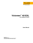
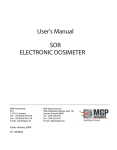
37-720
Dual-Diode Dosimeter Patient Dose Monitor
User Manual
January 2008
Manual No. 160111 Rev. 6
©2003, 2005, 2008 Fluke Corporation, All rights reserved. Printed in U.S.A.
All product names are trademarks of their respective companies
Fluke Biomedical
6045 Cochran Road
Cleveland, Ohio 44139
440.498.2564
www.flukebiomedical.com
Table of Contents
Section 1:
1.1
1.2
1.3
General Information................................................................................... 1-1
Introduction .................................................................................................. 1-1
Specifications............................................................................................... 1-2
Accessories ................................................................................................. 1-3
Section 2:
2.1
2.2
2.3
2.4
Operation.................................................................................................... 2-1
Battery Check .............................................................................................. 2-1
Zeroing the Instrument................................................................................. 2-1
Calibration.................................................................................................... 2-1
Making a Measurement ............................................................................... 2-2
Section 3:
3.1
3.2
Maintenance ............................................................................................... 3-1
Battery Replacement ................................................................................... 3-1
Diode Cleaning Instructions ......................................................................... 3-1
i
(Blank page)
General Information
Introduction
1
Section 1
General Information
1.1 Introduction
System Description
The Dual-Diode Dosimeter Patient Dose Monitor combines a compact, battery operated, electrometer
with a silicon diode detector. The detector can be placed anywhere external to the patient for dose
verification and is easily held in position by taping to the skin.
The diode can be taped directly to the patient’s skin to obtain data for TLD readout values, eliminating
TLD measurements. Irregular field dosimetry is easily performed with this system. No temperature
pressure corrections need be applied to values obtained during the measurement process. The system
allows accurate and reproducible dose and dose rate data to be obtained without the necessity of
temperature equilibration or warm-up time.
Measurements can be read directly on the 3½-digit liquid crystal display (LCD) readout, eliminating
complex calculations. The electrometer has two detector inputs on the rear panel labeled DET A and
DET B. Each input has a range of 0 through 1999 cGy or cGy/min. A front panel switch enables the
selection of the detector input being utilized. Each detector has a clearly marked, screwdriver adjustable
set of calibration and zero controls mounted conveniently on the front panel. A quick response reset
button, also on the front panel, sets the system up for the next reading.
Patient Dose Monitor Model 37-720 is designed specifically for use with the silicon diode detectors
(positive output) recommended by Fluke Biomedical, Radiation Management Services (see Section 1.3).
The electrometer must be calibrated for each individual detector and radiation source.
A special feature inherent in the 37-720 is the ability to switch between DET A and DET B, using the front
panel switch, so that two detectors can be utilized for monitoring at the same time. This feature is
applicable when the measurement is being taken in the dose or rate mode. Measurements can be taken
in DOSE or RATE depending on the setting of the function switch. If it is desired to switch from one mode
to another, the RESET switch can be pressed to zero the electrometer.
1-1
37-720
User Manual
1.2 Specifications
Range
cGy: 0 to 2000
cGy/min: 0 to 2000
Sensitivity
.25 nC/cGy – 2 nC/cGy
Calibration Adjustments Front panel screwdriver adjustments:
CAL A and CAL B used for calibration of detector A and detector B.
ZERO A and ZERO B used to set up zero for detector A and detector B. CAL
A and CAL B used for calibration of detector A and detector B.
ZERO A and ZERO B used to set up zero for detector A and detector B.
Front Panel Controls
Power Switch: ON/OFF
Function Switch: DOSE or RATE modes of operation
Detector Switch: DET A or DET B selects detector input.
Reset Switch: Resets & zeros monitor for dose measurements.
Rear Panel Controls
Two BNC connectors for DET A input and DET B input.
Display
A 3 ½-digit liquid crystal display provides direct reading of the measurement
Accuracy
+ 5 % of full scale, current and charge
Rads Holding Drift
Better than 1 % / minute
Batteries Required
One 9 V alkaline cell (Duracell MN1604 or equivalent)
Battery Check
LO BAT appears on display when battery voltage drops below approximately 6 V
Battery Life
Approximately 150 hours
Case
Ivory, high impact plastic
Dimensions
(H x W x D)
2.5 in x 6.25 in x 8 in
(6.4 cm x 15.9 cm x 20.4 cm)
Weight
1.5 lbs (0.68 kg)
Operating Conditions
10 °C to 45 °C (50 °F to 104 °F)
Maximum 90% Relative Humidity non-condensing
1-2
General Information
Specifications
1
Routine Cleaning
CAUTION
Do not immerse the Model 37-720 Dual-Diode
Dosimeter Patient Dose Monitor. The unit is not
waterproof. Liquid could damage the circuits. The
unit should be kept clean and free of dirt and
contamination. The unit may be cleaned by wiping
with a damp cloth using any commercially available
cleaning or decontaminating agent.
NOTE
Refer to the applicable diode manual for specific
response characteristics relative to diode
performance.
1.3 Accessories
Part Number
Description
30-492
Diode Detector Holder
88-490
Diode Extension Cable 30’
88-490-1000
Diode Extension Cable 10’
VeriDose Diodes
Model
Range
Polarity/Color
30-471
30-472
30-473
30-474
30-475
1-4 MV
5-11 MV
12-17 MV
18-25 MV
5-25 MeV
Positive/Blue
Positive/Yellow
Positive/Red
Positive/Green
Positive/Grey
Buildup
Type
Cu
Cu
W
W
Buildup
(g/cm2)
0.732
1.359
2.606
3.574
0.284
Electrometer
37-720
37-720
37-720
37-720
37-720
1-3
(Blank page)
Operation
Battery Check
2
Section 2
Operation
2.1 Battery Check
Model 37-720 Dual-Diode Dosimeter Patient Dose Monitor is shipped with the battery installed.
Turn power on by placing the ON/OFF switch to the ON position, then look at the upper left hand corner
of the display. If the battery is low, a LO BAT message will appear on the display.
NOTE
If a probe has been connected, remove it until the
zero adjustments are complete.
2.2 Zeroing the Instrument
Place the function switch in the DOSE position and the detector switch in the DET A position. Press the
RESET button. In approximately five to seven seconds, a zero reading will appear on the display. If the
zero reading does not appear, adjust the ZERO A control using a small screwdriver until a zero reading is
obtained. The RESET switch should be held in while zeroing the instrument.
Once the RESET switch is released, the display will remain at zero and drift less than 1% of full scale in
one minute. Repeat this process for DET B, if necessary.
Place the function switch in the RATE position and the detector in the DET A position. The display will
show a value, but it should show a zero value in approximately five to seven seconds. Repeat this
process for DET B. The monitor will zero automatically when it is used in the RATE position, so it is not
necessary to use the RESET switch.
Connect the probe or probes to the rear panel connectors. Before taking readings, each probe should be
calibrated as discussed in the following paragraphs.
2.3 Calibration
Calibration is performed by positioning the diode at a point in a phantom where the dose is accurately
known. The screwdriver adjustment (CAL A or CAL B), located on the front panel, can now be
performed. Adjust CAL A or CAL B (depending on the detector being calibrated), until the indicated dose
or dose rate appears on the display.
2-1
37-720
User Manual
NOTE
If two detectors are connected, alternate readings
can be taken by switching between DET A and
DET B.
Both detectors should be calibrated
concurrently.
The highest degree of calibration can be attained
by calibrating at a dose or dose rate near ½ scale
(1000 cGy or 1000 cGy/min). This is due to display
resolution.
After the battery check, instrument zeroing, and calibration have been performed, measurements can be
taken.
2.4 Making a Measurement
Rate: cGy/min
1. Zero the instrument if not previously zeroed. Refer to "Zeroing the Instrument", at the beginning of
Section 2.2.
2. Connect the appropriate probe/probes to the DET A, DET B inputs.
3. Select the RATE mode on the front panel.
4. Initiate a radiation exposure.
5. During the exposure, view the reading on the display.
Dose Mode: cGy
1. Zero the instrument if not previously zeroed. Refer to "Zeroing the Instrument", at the beginning of
Section 2.2.
2. Connect the appropriate probe/probes to the DET A, DET B inputs.
3. Select the DOSE mode on the front panel.
4. Initiate a radiation exposure.
5. Upon completion of the exposure, view the results on the front panel display.
6. Alternate between DET A and DET B to view both channels.
2-2
Maintenance
Battery Replacement
3
Section 3
Maintenance
3.1 Battery Replacement
If the LO BAT message appears on the display, the battery should be replaced. Turn the power off.
Open the battery compartment (located on the rear panel). Pry on the rippled side to open the door and
gain access to the battery. Remove the old battery and replace it with a new one. When disconnecting
or reconnecting a battery, take care not to damage the connector as it is attached to short leads.
3.2 Diode Cleaning Instructions
The diodes may be cleaned with an alcohol swab or any disinfectant, which is commonly used in hygienic
care.
(Reference only, not to
scale)
Figure 3-1. Component Layout Diagram (160010)
3-1
(Blank page)
(Blank page)
Fluke Biomedical
6045 Cochran Road
Cleveland, Ohio 44139
440.498.2564
www.flukebiomedical.com