1
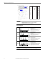
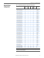
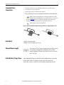
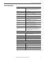
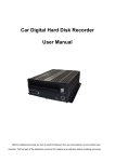
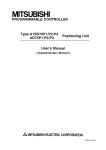
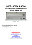
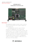
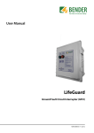
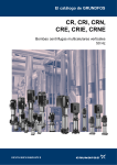
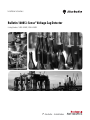
Installation Instructions Bulletin 1608S i-Sense® Voltage Sag Detector Catalog Numbers: 1608S-3V480K, 1608S-6V480K Important User Information Solid-state equipment has operational characteristics differing from those of electromechanical equipment. Safety Guidelines for the Application, Installation and Maintenance of Solid State Controls (publication SGI-1.1 available from your local Rockwell Automation sales office or online at http://www.rockwellautomation.com/literature/) describes some important differences between solid-state equipment and hard-wired electromechanical devices. Because of this difference, and also because of the wide variety of uses for solid-state equipment, all persons responsible for applying this equipment must satisfy themselves that each intended application of this equipment is acceptable. In no event will Rockwell Automation, Inc. be responsible or liable for indirect or consequential damages resulting from the use or application of this equipment. The examples and diagrams in this manual are included solely for illustrative purposes. Because of the many variables and requirements associated with any particular installation, Rockwell Automation, Inc. cannot assume responsibility or liability for actual use based on the examples and diagrams. No patent liability is assumed by Rockwell Automation, Inc. with respect to use of information, circuits, equipment, or software described in this manual. Reproduction of the contents of this manual, in whole or in part, without written permission of Rockwell Automation, Inc., is prohibited. Throughout this manual, when necessary, we use notes to make you aware of safety considerations. WARNING: Identifies information about practices or circumstances that can cause an explosion in a hazardous environment, or which may lead to personal injury or death, property damage, or economic loss. ATTENTION: Identifies information about practices or circumstances that can lead to personal injury or death, property damage, or economic loss. Attentions help you identify a hazard, avoid a hazard, and recognize the consequence. SHOCK HAZARD: Labels may be on or inside the equipment, for example, a drive or motor, to alert people that dangerous voltage may be present. BURN HAZARD: Labels may be on or inside the equipment, for example, a drive or motor, to alert people that surfaces may reach dangerous temperatures. IMPORTANT Identifies information that is critical for successful application and understanding of the product. Allen-Bradley, Rockwell Software, Rockwell Automation, and i-Sense are trademarks of Rockwell Automation, Inc. Trademarks not belonging to Rockwell Automation are property of their respective companies. Additional Resources These documents contain additional information concerning this and related products from Rockwell Automation. Resource Description Bulletin 1608S i-Sense® Voltage Sag Detector, User Manual, publication 1608S-UM001_-EN-P Provides installation, configuration, operation, maintenance , specifications, and certification information. Industrial Automation Wiring and Grounding Guidelines, publication 1770-4.1 Provides general guidelines for installing a Rockwell Automation industrial system. Product Certifications website, http://www.ab.com Provides declarations of conformity, certificates, and other certification details. You can view or download publications at http:/www.rockwellautomation.com/literature/. To order paper copies of technical documentation, contact your local Allen-Bradley distributor or Rockwell Automation sales representative. Bulletin 1608S i-Sense® Installation Instructions Installation Pre-installation 1. Inspect for shipping damage 2. Record the i-Sense® serial number * 3. Register the i-Sense at www.igrid.com* 4. Configure the i-Sense hardware for the service voltage * 5. Configure communications software using the Ethernet port. (this can be done after installation and power-up) * For more information, please refer to Rockwell Automation Publication 1608S-UM001-EN-P WARNING: Do not apply power to the i-Sense until the wiring is completed and right-side cover is replaced. Installation must be performed by an electrician, in accordance with all local and national codes. Environmental Conditions The i-Sense is rated for installation in the following environment: • Indoor use only, no conductive pollution. • Altitude up to 2000 m (6500 ft) • Temperature range +0...+40 °C (+32...+104 °F) • Maximum relative humidity 95%, non-condensing. Mounting • Provide 10 inches (250 mm) clearance around the i-Sense for cooling and access. • Remove the left and right covers (four Phillips-head screws, two top and two bottom) • Mount the i-Sense to a vertical surface using the four mounting holes. Two of the four mounting screws should penetrate into studs at least 1 in. (25 mm). Mounting screws 1.5 in. (38 mm) long are recommended. Electrical Connections • Branch protection: upstream fuse or circuit breaker protection rated 20A or less is required. Protection rated less than 5 A is not recommended. • Conduit entry: top or bottom. • Connect the Ground (Earth) wire to the #10-32 stud near the bottom knock-out. • Connect mains line to the INPUT_1 terminal block, according to the proper wiring diagram from Table 1. • 6-Channel Version: if the INPUT_2 terminal block is present, wire the second 3-phase set using the same wiring diagram. • Verify that the JP1 plug is properly configured, per Table 2: The plug with RED wires must be installed if the channel voltage is greater than 250 VAC. WARNING: This unit is not rated for 600V AC or 690V AC L-L installations. 600Y/346V installations require 4-wire L-N wiring method. The neutral must be connected as shown inTable 1. • Replace the right-side cover and two screws Rockwell Automation Publication 1608S-IN001A-EN-P - July 2013 3 Bulletin 1608S i-Sense® Installation Instructions 1. Select your voltage configuration from Table 2and follow the instructions in the corresponding wiring diagram from Table 1. L e f t 2. Use the appropriate wiring diagram and jumper wire positions. The i-Sense is shipped with jumper wires in the LL configuration. The LL and LN diagrams are also shown inside the i-Sense cover. Move or remove jumper wires as needed. NORMAL ERROR C o v e r R i g h t C o v e r IMPORTANT • There should be no more than one wire installed at each terminal block position • Maximum 480V per channel • 575Y/332V and 600Y/364V systems must use the 346 (L-N) configuration • 690Y/400V systems must use the 400 (L-N) configuration Table 1 - Wiring Diagrams Source type L1 (N or L2) S1 Single phase 1 2 3 4 5 6 L1 N 7 8 9 L2 Wiring Diagram 1 channel sensing GND 2 wires + ground required No jumper wires Use AWG 14-22 (.34-2.5 mm²), 600V AC conductors Tighten screws to 12-13 lb-in (1.4 Nm) Tighten ground stud nut to 30 lb-in (3.4 Nm) The ground stud is #10-32. GND 2 channel sensing 3 wires + ground required Jumper pins 3-5 Use AWG 14-22(.34-2.5 mm²), 600 VAC conductors Tighten screws to 12-13 lb-in (1.4 Nm) Tighten ground stud nut to 30 lb-in (3.4 Nm) The ground stud is #10-32. GND 3 channel sensing 4 wires + ground required Jumper pins 3-5 & 6-8 Use AWG 14-22(.34-2.5 mm²), 600V AC conductors Tighten screws to 12-13 lb-in (1.4 Nm) Tighten ground stud nut to 30 lb-in (3.4 Nm) The ground stud is #10-32. GND 3 channel sensing 3 wires + ground required Jumper pins 1-6 & 3-7 & 4-9 Use AWG 14-22(.34-2.5 mm²), 600V AC conductors Tighten screws to 12-13 lb-in (1.4 Nm) Tighten ground stud nut to 30 lb-in (3.4 Nm) The ground stud is #10-32. S2 Split-phase 1 2 3 4 5 6 7 8 9 L1 N L3 L2 LN 3-Phase 4-wire 1 2 3 4 5 6 L1 L2 7 8 9 L3 LL 3-Phase 3-wire 1 2 3 4 5 6 IMPORTANT 4 7 8 9 See i-Sense Management Console to set the nominal voltage. Rockwell Automation Publication 1608S-IN001A-EN-P - July 2013 Bulletin 1608S i-Sense® Installation Instructions Nominal Voltage Configurations Table 2 - Nominal Voltage Configurations. (shipped standard with 480V (L-L) Your Voltage Nominal Volts per Channel Channels Mains Wires Wiring Diagram (See Table 2) Power Supply Jumper JP1 Any single-phase voltage ≤240V nominal 1 2 S1 White wires 100 (L-N for 100/200V split-phase) 100 2 3 S2 White wires 105 (L-N for 105/210V split-phase) 105 2 3 S2 White wires 110 (L-N for 190Y/110V 3-phase) 110 3 4 LN White wires 115 (L-N for 200Y/115V 3-phase) 115 3 4 LN White wires 115 (L-N for 115/230V split-phase) 115 2 3 S2 White wires 120 (L-N for 208Y/120V 3-phase) 120 3 4 LN White wires 120 (L-N for 120/240V split-phase) 120 2 3 S2 White wires 125 (L-N for 216Y/125V 3-phase) 125 3 4 LN White wires 127 (L-N for 220Y/127V 3-phase) 127 3 4 LN White wires 133 (L-N for 230Y/133V 3-phase) 133 3 4 LN White wires 139 (L-N for 240Y/139V 3-phase) 139 3 4 LN White wires 190 (L-L for 190Y/110V 3-phase) 190 3 3 LL White wires 200 (L-L for 100/200V split-phase) 200 1 2 S1 White wires 208 (L-L for 208Y/120V 3-phase) 208 3 3 LL White wires 210 (L-L for 105/210V split-phase) 210 1 2 S1 White wires 216 (L-L for 216Y/125V 3-phase) 216 3 3 LL White wires 220 (L-L for 380Y/220V 3-phase) 220 3 3 LL White wires 230 (L-L for 230Y/133V 3-phase) 230 3 3 LL White wires 230 (L-N for 400Y/230V 3-phase) 230 3 4 LN White wires 240 (L-L for 120/240V split-phase) 240 3 3 LL White wires 240 (L-N for 415Y/240V 3-phase) 240 3 4 LN White wires 254* (L-N for 440Y/254V 3-phase) 254 3 4 LN Red wires 277 (L-N for 480Y/277V 3-phase) 277 3 4 LN Red wires 346 (L-N for 600Y/346V 3-phase) 346 3 4 LN Red wires 346 (L-L for 346Y/200V 3-phase) 346 3 3 LL Red wires 380 (L-L for 380Y/220V 3-phase) 380 3 3 LL Red wires 400 (L-L for 400Y/230V 3-phase) 400 3 3 LL Red wires 400 (L-N for 690Y/400V 3-phase) 400 3 4 LN Red wires 415 (L-L for 415Y/240V 3-phase) 415 3 3 LL Red wires 440 (L-L for 440Y/254V 3-phase) 440 3 3 LL Red wires 440 (L-L for 220/440V split-phase) 440 3 3 LL Red wires 460 (L-L, at point of use) 460 3 3 LL Red wires 480 (L-L for 480Y/277V 3-phase) 480 3 3 LL Red wires 600 (L-L 3-phase) not allowed No No No No No 690 (L-L 3-phase) not allowed No No No No No * Nominal 254V source must operate normally at > 240V (95% of nominal) ** Maximum 480V per channel. 575Y/332V and 600Y/346V systems must use the 346 (L-N) configuration. 690Y/400V systems must use the 346 (L-N) configuration. Rockwell Automation Publication 1608S-IN001A-EN-P - July 2013 5 Bulletin 1608S i-Sense® Installation Instructions Communications Connections 1. Remove left side cover (two Phillips-head screws, top and bottom) 2. Conduit entry: top or bottom. 3. Install appropriate communications cable(s)* * For more information, please refer to Rockwell Automation Publication 1608S-UM001-EN-P 8P8C (RJ45) modular Ethernet cable. Pass the Ethernet cable through the included RF filter core, and close the core securely, as shown in Figure 1. Failure to install the cable filter may result in RF emissions beyond the standards of the EU’s EMC Directive. RJ11 telephone line (analog PSTN) Figure 1 - Ethernet cable filter installation. The clip-on filter core is supplied with the i-sense. Final Check External Power Supply Initial Battery Charge Time 6 • Check all connections • Replace left and right side covers The external 9V DC power supply (not provided) is used only during configuration; it should not be used in normal operation. Remove the left-side cover to access the 9Vdc jack. The rechargeable batteries may become discharged after some time on the shelf. Allow 30 minutes charge time after power-up before the i-Sense is ready to record voltage interruption events. Rockwell Automation Publication 1608S-IN001A-EN-P - July 2013 Bulletin 1608S i-Sense® Installation Instructions Technical Specifications Electrical Nominal Voltage User-selectable, 100V-480Vrms, 1-Phase or 3-Phase Immune to voltage fluctuation up to ±10% of nominal and transient over voltages typically present on mains supply (impulse withstand Category II of IEC 60364-4-443) Frequency 45...65 Hz, auto-sensing Measurement inputs 1 to 3 channels, Cat. No.: 1068S-3V480K (3-channel) Up to 6 channels, Cat. No.: 1068S-6V480K (6-channel) RMS voltage measurement accuracy 0.2% typical, ± 2% maximum (of full-scale) True rms Sample rate 5760 sample/second Waveform capture rate 32 samples/cycle Time Stamp ±0.1 seconds typical accuracy Real-time clock synchronized to UTC (NIST standard) daily, via i-Grid and SNTP protocol Data Storage Non-volatile event storage > 300 events Memory cleared after automatic up load to i-Grid. Voltage Deviation Event detection trigger. 1/2-cycle rms voltage ≤ 87% or ≥115% of set nominal Adaptive waveform deviation detection of transient events. Voltage Deviation Event Storage 8 cycles waveform data (-1...+3 cycles at event start and -3...+1 cycles at the event end) Continuous rms voltage trend, up to 2 minutes. Periodic (PRMS) Data Logging Minimum, Maximum and Average rms voltage recorded for each 10-minute period. Min./Max. are lowest/highest sliding 1/2 -cycle rms period Power supply and battery backup Powered from Channel 1 (L1-L2 or L1-N), < 25VA load 9VDC external power supply (not provided - for configuration only) Rechargeable batteries enable measurement & communications during power interruptions for up to 2 minutes Mechanical & Environmental Enclosure NEMA 1 (IP20). Indoor use only. Only non-conducting pollution (degree II) Dimensions: 11.4” H x 9.7” W x 3.0” D (291 mm H x 247 mm W x 75 mm D) Weight 8.5 lb (3.6 kg) Operating Temperature 0...+ 40 °C (+32...+104 °F) Storage Temperature -40...+ 75 °C (-40...167 °F) Relative Humidity 0...95%, non-condensing Altitude 2000 m (6,562 ft) at +40 °C Communications Internet Communications Over port 80 via HTTP protocol. Outgoing only. Ethernet IEEE 802.3 10 Base-T (10 Mb/s), 8P8C (RJ45) modular connector Modem (optional) PSTN (analog telephone) RJ11 modular connector, Most global phone systems supported Indicators Red and green front-panel LEDs i-Sense Management Console On-board Web server for configuration and status, password protected. Rockwell Automation Publication 1608S-IN001A-EN-P - July 2013 7 Bulletin 1608S i-Sense® Installation Instructions Standards Compliance and Certifications cTUVus (OSHA NRTL) listed Tested to UL and CSA safety standards CE mark (Safety and EMC) RoHS compliant FCC part 68 (Telephone Equipment) FCC part 15 (Emissions) Industry Canada CS-03 (Telephone Equipment) European Union CTR21 (Telephone Equipment) Compliance Information • • • • • • • • FCC PART 68 • This equipment complies with Part 68 of the FCC rules and the requirements adapted by the ACTA. The finished product containing this equipment must display a product identifier in the format [US: 3A4MM00BTM]. If requested, this information must be provided to the telephone company. • This equipment uses the USOC jacks: RJ11C • A plug and jack used to connect this equipment to the premises wiring and telephone network must comply with the applicable FCC Part 68 rules and requirements adopted by the ACTA. This equipment is designed for connection to a compatible modular jack that is also compliant. See installation instructions for details. • The REN is used to determine the number of devices that may be connected to the telephone line. Excessive REN on the telephone line may result in the devices not ringing in response to an incoming call. In most, but not all areas, the sum of the REN should not exceed five (5.0). To be certain of the number of devices that may be connected to a line, as determined by the total REN, contact the local telephone company. The REN for this product is part of the product identifier that has the format: [US: 3A4MM00BTM] The digits shown after MM are the REN without decimal point. (e.g., 00 is a REN of 0.0) • If this equipment causes harm to the telephone network, the telephone company will notify you in advance that temporary discontinuance of service may be required. If advance notice isn’t practical, the telephone company will notify the customer as soon as possible. Also, you will be advised of your right to file a complaint with the FCC if you believe it is necessary. If the equipment is causing harm to the telephone network, the telephone company may request that you disconnect the equipment until the problem is resolved. The telephone company may make changes in its facilities, equipment, operations, or procedures that could affect the operation of the equipment. If this happens, the telephone company will provide advance notice in order for you to make the necessary modifications to maintain uninterrupted service. 8 Rockwell Automation Publication 1608S-IN001A-EN-P - July 2013 Bulletin 1608S i-Sense® Installation Instructions • The Telephone Consumer Protection Act of 1991 makes it unlawful for any person to use a computer or other electronic device including fax machines, to send any message unless such message clearly contains in a margin at the top or bottom of each transmitted page or on the first page of transmission, the date and time it was sent and an identification of the business or other entity, or other individual sending the message and the telephone number of the machine or such business, other entity, or individual. (The telephone number provided may not be a 900 number or any other number for which charges exceed local or long-distance transmission charges.) • Advisory notice: It is suggested that the customer use a surge arrestor on the AC power lines to which this device is connected. Telephone companies report that electrical surges, typically lightning transients, are very destructive to customer terminal equipment connected to AC power sources. This has been identified as a major nationwide problem. Industry Canada Notice • This product meets the applicable Industry Canada technical specifications. This is confirmed by the registration number. The abbreviation, IC, before the registration number signifies that registration was performed based on a Declaration of Conformity indicating that Industry Canada technical specifications were met. It does not imply that Industry Canada approved the equipment. • Le present materiel est conforme aux specifications techniques applicable d‘Industrie Canada. • The Ringer Equivalence Number (REN) for this terminal equipment is 0.0. The REN assigned to each terminal equipment provides an indication of the maximum number of terminals allowed to be connected to a telephone interface. The termination on an interface may consist of any combination of devices subject only to the requirement that the sum of the Ringer Equivalence Numbers of all the devices does not exceed five. • L‘findice d‘f equivalence de la sonnerie (IES) sert a indiquer le nombre maximal de terminaux qui peuvent etre raccordes a une interface telephonique. La terminaison d‘une interface peut consister en une combinaison quelconque de dispositifs, a la seule condition que la somme d‘findices d’fequivalence de la sonnerie de tous les dispositifs n‘fexcede pas 5. FCC Part 15 Class A Digital Equipment • Operation of this device is subject to the following two conditions: – This device must not cause harmful interference. – This device must accept any interference received including interference that may cause undesired operation. Rockwell Automation Publication 1608S-IN001A-EN-P - July 2013 9 Bulletin 1608S i-Sense® Installation Instructions • This equipment has been tested and found to comply with the limits for a Class A digital device, pursuant to Part 15 of the FCC Rules. This equipment generates, uses, and can radiate radio-frequency energy. If not installed and used in accordance with the instructions, it can cause harmful interference to radio communications. However, there is no guarantee that interference will not occur in a particular installation. If this equipment does cause interference to radio or television reception, which can be determined by turning the equipment off and on, the user is encouraged to try to correct the interference by one or more of the following measures: 1. If it can be done safely, try to reorient or relocate the receiving antenna. 2. Increase the separation between the modem and the receiver. 3. Connect the modem to an outlet on a different circuit from the receiver. 4. Consult the dealer or an experienced radio/TV technician for help. ATTENTION: This is a class A product that is intended for use in an industrial environment. This product is not intended to be installed in a residential, commercial or light industrial environment, it may cause radio interference in these environments. CTR21 Statement This equipment has been approved to [Council Decision 98/482/EC-”CTR 21”h] for pan-European single terminal connection to the Public Switched Telephone Network (PSTN). However, due to differences between the individual PSTN’s provided in different countries, the approval does not, of itself, give an unconditional assurance of successful operation on every PSTN termination point. In the event of a problem, you should contact your equipment supplier in the first instance. Contact your local Rockwell Automation sales office or Allen-Bradley distributor for use in other locations not specified in the compliance information listed above. 10 Rockwell Automation Publication 1608S-IN001A-EN-P - July 2013 Rockwell Automation Support Rockwell Automation provides technical information on the Web to assist you in using its products. At http://www.rockwellautomation.com/support, you can find technical manuals, technical and application notes, sample code and links to software service packs, and a MySupport feature that you can customize to make the best use of these tools. You can also visit our Knowledgebase at http://www.rockwellautomation.com/knowledgebase for FAQs, technical information, support chat and forums, software updates, and to sign up for product notification updates. For an additional level of technical phone support for installation, configuration, and troubleshooting, we offer TechConnectSM support programs. For more information, contact your local distributor or Rockwell Automation representative, or visit http://www.rockwellautomation.com/support/. Installation Assistance If you experience a problem within the first 24 hours of installation, review the information that is contained in this manual. You can contact Customer Support for initial help in getting your product up and running. United States or Canada 1.440.646.3434 Outside United States or Canada Use the Worldwide Locator at http://www.rockwellautomation.com/rockwellautomation/support/overview.page, or contact your local Rockwell Automation representative. New Product Satisfaction Return Rockwell Automation tests all of its products to help ensure that they are fully operational when shipped from the manufacturing facility. However, if your product is not functioning and needs to be returned, follow these procedures. United States Contact your distributor. You must provide a Customer Support case number (call the phone number above to obtain one) to your distributor to complete the return process. Outside United States Please contact your local Rockwell Automation representative for the return procedure. Documentation Feedback Your comments will help us serve your documentation needs better. If you have any suggestions on how to improve this document, complete this form, publication RA-DU002, available at http://www.rockwellautomation.com/literature/. Publication 1608S-IN001A-EN-P - July 2013 DIR #10000704248 Copyright © 2013 Rockwell Automation, Inc. All rights reserved. Printed in the U.S.A