1
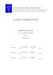
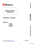
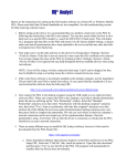
SERVICE MANUAL
PARTS LIST
SERVICE
BURNISHER
MODELS:
B-1500 P
B-1500 DC
KOBLENZ ELECTRICA S.A. DE C.V.
E-mail: [email protected]
October-06
LP-B1500-200610
1/10
October/ 2006
INDEX
PAGE
3
I.- FINAL TEST PRODUCT SAFETY
II.- REPLACEMENT PROCEDURES ASSEMBLY
3
III.- TROUBLE SHOOTING CHART
5
IV.- ELECTRICAL RATING
6
V.- WIRING DIAGRAM
6
VI.- PART LIST
7
VII.- ASSEMBLY
9
2/10
October/ 2006
I. FINAL TEST FOR PRODUCT SAFETY
AT THE COMPLETION OF ANY REPAIR THE PRODUCT SHOULD BE ELECTRICALLY TESTED FOR
OPERATING AND ELECTRIC TEST AS FOLLOWS
ELECTRIC TEST
A). - Set hi-pot meter at 1500 V
B): -Place Switch Lock to on position.
c). -Touch one probes of tester to on blade of power cord plug and touch other probe to handle tube.
There should be no breakdown.
OPERATING TEST
RUN THE MACHINE ON HARD SURFACE WITH BRUSH OR PAD AND MAKE SURE:
A). - THERE IS NO UNUSUAL NOISE OR VIBRATION
B). - THE MOTOR STARTS FAST AND WITH OUT NOISE
C). - THE CURRENT DRAW IS LESS THAN 15 AMP.
II. - REPLACEMENT PROCEDURES ASSEMBLY
1. - INDUCTION MOTOR ASSEMBLY REPLACEMENT (52 )
1.1. - Disconnect the line cord ( 46) from the motor line cord ( 47)
1.2. - Place the burnished in vertical position. Unscrew the center driver ( 99 ) counterclockwise the three
screws ( 98 ) as well as the base fix ( 99 )
1.3. -Remove the six screws ( 97 ) the flex base ( 96 ) the five screws ( 86 ) five washers ( 85 ) and the
plate ( 83-A )
1.4. - Loosen the four screws ( 63 ) pull the motor from the pulley disc ( 90 ) remove the belt
1.5. - Remove the Allen screw ( 72 ) the motor pulley ( 73 ) as well as the locking pin ( 71 ) place the
burnished in normal position and remove the handle tube assembly.
1.6.-Remove the three screws ( 54 ) lift the motor cover ( 44 ) remove the connection box from the motor,
and disconnect the three leads of the motor line cord assembly ( 47 ) also removing the motor cover
( 44 )
1.7.- Remove the molding motor cover ( 46 ) four screws ( 61 ) the two capacitor covers ( 60 ) the two
capacitor insulators ( 58 ) disconnect the two capacitors ( 57 and 58 )
1.8.- Place the burnisher in position down, remove the four screws ( 63 ) the washer ( 70 ) as well as the
four washers ( 62 )
1.9.- Remove the assembly chassis ( 80 ) only the motor ( 52 ) that is assembly cover motor ( 44 ) as
well as the molding motor cover ( 46 )
1.10.- Replace the motor assembly and reassemble
NOTE : When replacing the motor ,make sure the replace has same characteristics it’s also
important the two capacitors to place and connect the capacitors as initially placed to avoid
damaging the motor and alignment from pulleys .
3/10
October/ 2006
2..-TO REPLACED BELT ( 77 )
2.1,- Follow steps indicated on point 1-2,1-3 and 1-4
2.2.- Replace belt and reassemble alignments from pulleys
3..- PULLEY AXLE REPLACEMENT ( 87 )
3.1.- Follow steps 1-2,1-3, and 1-4.
3.2.- Remove the elastic bolt ( 94 ) pressure washer ( 95 ) and flat washer ( 93 )
3.3.- Remove the pulley flex disc ( 90 ) which is assembled with two bearings ( 91 ) the bearing separator
( 92 ) and clamp ( 89 )
3.4.- Remove the four bolts ( 88 ) pressure washer ( 79 ) remove the pulley axle and reassemble.
NOTE : Pulley axle ( 87 ) and chassis ( 80 ) bolt holes can be assembled one way only, therefore if the bolt
holes are not aligned when attaching the pulley axle to the chassis ,rotate the pulley axle until the holes
are aligned and allow the four screws ( 51 ) to pass freely
4.- BEARING REPLACEMENT ( 91 )
4.1.- Follow steps 1-2,1-3 and 1-4.
4.2.- Follow steps 3-2, and 3-3
4.3.- Remove the clamp ( 89 ) the two bearings ( 91 ) as well as the bearing separator.
4.4.- Replace the two bearings, and reassemble.
5..-ON-OFF HANDLE REPLACEMENT ( 1 )
5.1.- Remove the two screw ( 8 ) and two washers ( 9 )
5.2.- Remove the screw ( 4-A ) and sure button ( 4-B ).
5.3.- Remove the switch box cover black ( 7 )
5.4.- Remove the two bolts with head ( 11 ) and two springs ( 2 )
5.5.- Replace the ON-OFF handle, and reassemble.
6..- MICRO SWITCH REPLACEMENT ( 27 )
6.1.- Follow Steps 5-1,5-2 and 5-3
6.2.- Disconnect her connection micro switch
6.3.- Remove the two screw ( 29 ) and two washers ( 28 )
6.4.- Remove and replace the micro switch and switch insulator ( 26 ) as originally assembled.
7.- ASSEMBLY SURE REPLACEMENT ( 4 )
7.1.- Follow steps 5-1,5-2 and 5-3.
7.2.- Remove the dust cover ( 4-G ) and two screws ( 4-F)
7.3.- Remove the assembly sure and replace the component damaged and reassemble
8..- LINE CORD ASSEMBLY REPLACEMENT ( 32 )
8.1.- Follow steps 5-1,5-2 and 5-3 .
8.2.- Disconnect the ground ( green ) as well as the lead connected to micro switch ( 27 ) and the cable
switch assembly ( 14 ) connect to the thermal protector ( 16 )
8.3.- With Heyco pliers, remove the grommet ( 33 ) and washer ( 34 ) remove the motor lead assembly
( 32 ) as well as the grommet line tube ( 35 )
8.4.- Replace the motor lead by inserting the handle assembly ( 10 ) upwards and previously placing the
grommet tube ( 35 )
8.5.- Place the washer ( 34 ) as well as the grommet ( 33 ) at the same distance as the prior lead
,connect and reassemble as initially placed.
4/10
October/ 2006
9.- LINE CORD REPLACEMENT ( 40 )
9.1.-Follow steps 5-1,5-2 and 5-3.
9.2.- Disconnect ground (green ) as well as connection micro switch ( 27 ) and the connect to thermal
protector ( 16 )
9.3.-Remove the nut from the effort relief assembly ( 38 )
9.4.- Replace line cord ,connect and reassemble as initially placed
WHEN ORDERING ,DO NOT FORGET TO SPECIFY :
PART NUMBER
DESCRIPTION
MODEL NUMBER
NOTE: Drawing numbers are for identification purposes only.
III.- TROUBLE SHOOTING CHART
1.MOTOR DOES NOT START
POSSIBLE CAUSE
SOLUTION
NOT PLUGGED IN PROPERLY
CHECK CONNECTION
LINE CORD DAMAGED
REPLACE
MICRO SWITCH DAMAGED
REPLACE MICROSWITCH
CIRCUIT BREAKER OFF
RESET BREAKER
CAPACITOR DAMAGED
REPLACE CAPACITOR
MOTOR LINE CORD DAMAGED
REPLACE MOTOR LINE CORD
MOTOR ASSEMBLY DAMAGED
REPLACE MOTOR ASSEMBLY
PISTON AND SPRING DAMAGED
REPLACE
2..-MOTOR WORKS BADLY
POSSIBLE CAUSE
LOW VOLTAGE
CAPACITOR DAMAGED
IMPROPER MOTOR CONNECTIONS
SOLUTION
CHECK VOLTAGE ( LINE )
REPLACE CAPACITOR
CHECK CONNECTION
3. MOTOR STARTS ,DOES NOT RUN DRIVER
POSSIBLE CAUSE
BELT DAMAGED
MOTOR PULLEY DAMAGED
PULLEY AXLE DAMAGED
SOLUTION
REPLACE BELT
REPLACE MOTOR PULLEY
REPLACE PULLEY AXLE
4.-MOTOR NOISY
POSSIBLE CAUSE
BEARING DAMAGED
SOLUTION
REPLACE BEARING
5/10
October/ 2006
IV. ELECTRICAL RATING /
120 V ~
60 Hz
15 A
V .-WIRING DIAGRAM
6/10
October/ 2006
VI.-PART LIST
No.
PART. No.
1
2
3
4
4-A
4-B
4-C
4-D
4-E
4-F
4-G
4-H
4-I
4-J
6
7
8
9
10
10
11
12
13
14
16
17
18
26
27
28
29
30
31
32
33
34
35
36
37
38
39
40
41
42
44
45
46
47
47
49
51
52
52
53
54
55
05-3979-1
24-0292-3
12-0830-5
45-0534-3
01-0272-3
13-2209-8
13-2205-6
13-2206-4
13-2208-0
01-1732-5
37-0225-5
05-3536-9
24-0292-3
13-2207-2
17-3783-2
05-3975-9
01-1984-2
04-0276-8
23-0657-9
23-0656-1
03-0593-8
01-1256--5
17-3677-6
28-0958-0
38-0338-4
04-0271-9
02-0015-4
08-1857-5
11-0096-5
04-0275-0
01-0851-4
04-0493-9
01-0852-2
28-0955-6
12-0414-8
04-0036-6
12-0115-1
01-1724-2
06-0486-8
45-0456-9
10-0140-3
28-1078-6
17-3036-5
12-0414-8
05-3765-4
17-3025-8
12-0692-9
28-0671-9
28-0957-2
01-1626-9
01-1745-7
00-1736-8
44-0344-0
02-0071-7
01-0068-5
12-0024-5
DESCRIPTION
Starter lever
Spring
Handle Tube Upper
Kit spare assembly sure
Screw # 6 x 1/2
Sure Button
Piston of the Insurance
Sure
It Cover Box it Guides of the Insurance
Screw # 8-32 x 1/2 "
Dust Cover
Tubular Separator
Spring
Box Guides of the Insurance
Switch Box Label Burnisher
Switch Box Cover Black
Screw # 8-32 x 1 "
Star Washer No 8
Assemble Handle for Switch
Assemble Handle
Bolt with Head
Screw Phillips 10-24 x 3/4
Label " Reset "
Switch Assy Wire
Thermal Protector 20 A
Star Washer No 10
Hexagonal Nut 10-24
Insulator Switch
Micro Switch
Star Washer No 6
Screw hexagonal 6-32 x 1"
Star Washer No 8
Screw hexagonal 6-32 x 3/8 "
Motor Cable / Contac Assembly
Grommet Heyco 0.062
Washer
Grommet of Rubber
Allen Screw 5/16-24 x 3/4
Hook Cord
Cord Strain Relief
Connector of pressure 2 x 14
Line Cord Assembly
Motor Cover 1.5 H.P. Insert
Grommet Heyco 0.062
Cover Motor
Koblenz Insert
Molding Motor Cover
Motor Cable / Contac Assembly
Motor Cable Assembly C.D.
Screw
Screw Cab. Car 5/16-18 x 1
Motor Induction
Motor C.D.
Nut Fastener
Screw No 8 x 3/8 "
Grommet
B-1550-P
B-1500-DC
1
2
2
1
1
1
1
1
1
2
1
2
1
1
1
1
2
2
1
2
2
1
1
1
1
1
1
2
1
2
1
1
1
1
2
2
1
1
2
1
1
2
2
1
1
1
1
1
1
1
1
1
1
1
1
1
1
1
2
1
4
1
3
3
2
7/10
2
2
1
1
1
2
2
1
1
2
2
1
1
1
1
1
1
1
1
1
1
1
1
1
1
1
2
1
1
4
1
3
3
October/ 2006
No.
PART. No.
DESCRIPTION
B-1550-P
B-1500-DC
56
56
57
58
59
60
61
62
63
64
23-0605-8
23-0615-7
15-0678-1
08-0979-8
15-0013-1
05-3567-4
01-1093-2
04-0366-7
01-1774-7
46-2422-7
Cover Motor C.D.
Cover Motor Assembly
Capacitor 40 MFD
Insulator Capacitor
Capacitor 590-708 MFD
Capacitor Cover
Screw Hexagonal 8 x 3/8 "
Flat Washer 3/8
Screw Hex 3/8-16 x 1 1/4 "
Lever Tube Adjustment Assy
64-A
65
66
67
68
69
70
71
72
73
73
74
12-0617-6
05-3582-3
06-0790-3
04-0073-9
01-1705-1
02-0134-3
04-0142-2
25-0021-3
01-1012-2
06-0760-6
06-0835-6
01-1704-4
Lever Grip
Washer
Clamp Tube
Flat Washer 3/8
Screw Hexagonal 3/8 "-16 x 2 1/2 "
Nut Security 3/8 " -16
Pressure Washer 3/8
Locking Pin
Allen Screw 3/8" -16 x 3/8
Motor Pulley
Motor Pulley C.D.
Screw Hexagonal 1/2-13 x 2
1
1
1
3
1
2
4
1
1
1
75
76
77
77
78
79
80
81
82
83-A
83-B
85
45-0396-7
45-0496-5
12-0672-1
12-0714-1
04-0074-7
04-0144-8
06-0799-4
03-0119-2
17-3550-5
23-0665-2
12-0809-9
04-0078-8
Wheel Assembly
Wheel Assembly
Belt
Belt Motor C.D.
Flat Washer 1/2
Pressure Washer 5/16 "
Chassis
U Rivet
"Precaution" Plate
Assembly Plate Burnisher
Assembly Plate Gasket
Flat Washer 1/4 "
2
2
1
2
4
1
2
1
1
1
5
1
2
4
1
2
1
1
1
5
86
87
88
89
90
91
92
93
94
95
96
97
01-1775-4
06-0757-2
02-0024-6
04-0521-7
06-0758-0
26-0187-0
04-0522-5
04-0567-0
02-0136-8
04-0154-7
46-2319-5
01-1077-5
Screw Hexagonal 1/4-20 x 3/4
Pulley Axle
Nut Hexagonal 5/16-18
Locking Ring
Disc Pulley
Bearing 6204
Spacer
Flat Washer Pulley Axle
Security Nut 5/8-18
Pressure Washer 5/8
Flex Base
Flat Screw 1/4-20 x 1
5
1
4
1
1
2
1
1
1
1
1
6
5
1
4
1
1
2
1
1
1
1
1
6
98
99
01-0069-3
13-1978-9
Screw No 8x1/2
Pad Holder
3
1
3
1
1
1
1
2
1
2
4
4
4
1
4
8/10
4
4
1
1
1
1
3
1
2
4
1
1
4
2
2
October/ 2006
X.- ASSEMBLY
9/10
October/ 2006
SERVICE
FACTORY AUTHORIZED SERVICE
Thorne Electric Company
610 Lanark Suite 205
San Antonio TX ,78218
Tel (210) 590-1226
Fax (210) 590-1258
1-800-548-5741
FACTORY
Koblenz Electrica ,S.A. de C.V.
Av. . Ciencia No 28 Cuautitlán Izcalli
Edo. de México ,C.P. 54730
Tel : 5864-0300
Web site : http://www.koblenz.electric.com
KOBLENZ ELECTRICA S.A. DE C.V.
E-mail: [email protected]
LP-APVI500-200509
10/10
October/ 2006