1
D9ed2-FE-uso
20-01-2006
14:58
Pagina 7
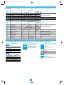
Table of standard parameters
If not specified, each the parameter must be doubled: one set for LOOP1 and one set for LOOP2. If the parameter is unique (1 parameter for both the loops) it is pointed out in
the notes column
Configuration
Mnemonic
code
IL
Prot
baud
PStr
Unit
Sc.dd
Sc.Hi
Sc.Lo
Parameter descritption
Digital input function IL
Communication protocol
Baud rate
Instrument position
Engineering unit
N° of decimals
Low range
High range
Setting range
Unit
see table 1
M.bus/Jbus
1200, 2400, 4800, 9600 baud
Alone/left side/central/right side
see table 2
0...3
-999...9999
Engineering unit
-999...9999
Engineering unit
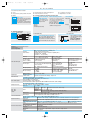
Alarms and auxiliary
Mnemonic
code
A1hy
A1SR
A1.tp
A1Lb
A1.O
t.Fil
In.Sh
Addr
Hi.PV
OP.lk
Ack
Nt.O1
RF.L
RF.H
RF
Parameter descritption
AL1 hysteresis
AL1 alarm source
AL1 alarm type
Latching/blocking alarm functions
AL1 output
Filter time constant
Input shift
Communications address
PV (measure) Hold
Output lock
Alarms acknowledge
Negate (NOT) OP1
RF low range
RF high range
Reference value
Setting range
Unit
0.1...10.0
% range
Loop 1/loop 2
See table 3
None/Ltch/Bloc/LtbL
Internal status/OP1/OP2/OP3/OP4
OFF/1...30
s
OFF/-60...+60
Digit
1...247
0/1
0/1
0/1
0/1
low range...RF. H
Engineering unit
RF. L...high range
Engineering unit
range
Engineering unit
Factory
setting
not used
M.bus
9600
Alone
none
0
Low range
High range
Factory
setting
0.5
Loop 1
Inhibited
None
Internal status
Inhibited
Inhibited
247
0
0
0
0
----------
Notes
Valid for both the channels
Linear scales only
Range min. 100 digit (linear scales only)
Notes
The same parameters are available also
for AL2, AL3 and AL4 alarms
Valid for both the channels
Locks the outputs OP1, OP2, OP3, OP4
Valid for both the channels
Available also for OP2 - OP3 - OP4
Standard parameters description
The parameters shown in the table are divided into groups which work in the same way. Below they will be described as they are listed in the table.
Configuration
IL
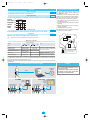
Digital input function - Table 1
Parameter decription
Not used
Loop 1 measure hold
Loop 2 measure hold
Hold both the measuring loops
Output locks
Alarms acknowledge
unit
Setpoint (SP)
A1S.P
A2S.P
A3S.P
A4S.P
AL1 - AL2 - AL3 - AL4 threshold
Alarm occurrences of AL1,AL2,AL3 and OP4.
The range of the alarm threshold
correspond to the whole span and it is not
limited by the SP Setpoint span.
Auxiliary parameters
A1.tp
A2.tp
A3.tp
A4.tp
Value
0
1
2
3
Alarm type
The parameter allows to specify how each
shoud function.
The types of alarm available are:
Action
Disable
Sensor/Loop Break
Absolute high
Absolute low
Engineering units - Table 2
Parameter description
°C (Centigrade degrees)
°F (Fahrenheit degrees)
None
mV (millivolt)
V (Volt)
mA (milliampere)
In.Sh
Input shift
This function shifts the whole PV scale of up to ±60 digits.
Parameter description
A (Ampere)
bar
psi
Rh
pH
Addr
Controller address
The address range is from 1 to 247 and must be unique
for each instrument on the communications bus to the
supervisor.
2