1
D9ed2-FE-uso
20-01-2006
14:58
Pagina 5
Commands
Communications parameters reset
Alarms acknowledge
The serial communications parameters can be reset to
the original factory settings (protocol: Modbus, Baud
Rate: 9600, Address: 247).
The instructions to remove/re-insert the I/O module from/in
its plastic case are described in the “Installation manual”.
After having removed the module, use the instructions
that follow to reset the communications parameters:
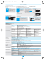
1) Use a jumper to short-circuit the terminals shown in
the drawing that follows;
2) Insert the I/O module in its housing and power ON the
instrument;
3) Extract the I/O module from its plastic case and remove
the short circuit jumper;
4) Reinstall the module in its housing.
At the end to this procedure, the communications parameters will be reset to its factory settings.
Ack
The acknowledge operation is performed by serial communications.
Negate output status
Nt.0x
Is possible to enable, separately for each output (DO1... DO4), the negate (NOT) fuction of the output internal logic status.
On
Internal
logic status Off
Enable NOT On
function
Off
On
Off
Output
status
PV Measure Hold
Hl.PV
Through the digital input IL is possible to hold the value of the PV measure (PV1, PV2 or PV1 and PV2).
Outputs lock
OP.lk
Output ports can be switched to OFF through the serial communications port.
Relay
AOOutputs lock status is maintained if the module is powered OFF
µP
Relay
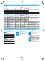
Digital input commands
Performed operation
Off
None
Hold PV1 measure
Hold PV2 measure
Hold PV1 and PV2 measures
Normal operation
Normal operation
Normal operation
Outputs status not
influenced
Outputs lock
Alarms acknowledge
Alarms active
Notes
On
T
Function
Not used
PV1 is hold
The value of PV (PV1 or/and PV2) is
PV2 is hold
“frozen” at the time the digital input
PV1 and PV2 are hold goes to the close state
digital IL command inhibits all the
Outputs in OFF status The
outputs at the same time
digital IL command acnowledges
Alarms acnowledged The
all the alarms active at the same time
In order to reset the serial communication
parameters to their default values, use a
junper to short-circuit the indicated
terminals
A function can be assigned, through the configuration procedure, to digital input. The configured function is activated when
the digital input (free voltage contact or open collector output) is in the ON status (closed). The function is reset to the normal operation by setting the input to the OFF status (open).
Activating the function through the digital input has the highest priority than the keypad or the serial communications command activation.
Warranty
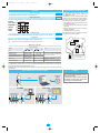
Serial communications connection example
Configuration
D9
Configuration
Cd-Rom
1
5
2
6
3
7
4
8
RS485
D9
OP1
OP2
OP3
OP4
PWR
COM
9 10 11 12
13 14 15 16
For SCADA
Local control
PC with
Autolink
31 max. instruments
1
5
2
6
3
7
4
8
1
5
2
6
3
7
4
8
D2
D9
1
5
D2
2
6
3
7
4
8
1
5
2
6
3
7
4
8
D2
31 max. instruments
D9
1
5
2
6
3
7
4
8
D9
RS485
1
5
2
6
3
7
4
8
1
5
2
6
3
7
4
8
D2
D9
1
5
D2
2
6
3
7
4
8
1
5
2
6
3
7
4
8
D2
OP35
operator
panel
D9
1
5
2
6
3
7
OP1
OP1
OP1
OP2
OP2
OP2
OP2
OP3
OP3
OP4
OP4
PWR
COM
9 10 11 12
13 14 15 16
PWR
COM
9 10 11 12
13 14 15 16
9 10 11 12
9 10 11 12
13 14 15 16 13 14 15 16
9 10 11 12
13 14 15 16
OP3
OP3
OP4
OP4
PWR
COM
9 10 11 12
13 14 15 16
4
8
D9
OP1
PWR
COM
9 10 11 12
13 14 15 16
9 10 11 12
9 10 11 12
13 14 15 16 13 14 15 16
9 10 11 12
13 14 15 16
4
RS485
We warrant that the products will be free from
defects in material and workmanship for 3 years
from the date of delivery.
The warranty above shall not apply for any failure
caused by the use of the product not in line with
the instructions reported on this manual.