1
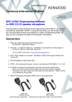
NEXEDGE™ Recording Gateway Rev A1 January 2012 1 Chapter 1 – Introduction ............................................................ 1 Contact Raven Electronics .......................................................................................................................................1 Raven Electronics’ Warranty and Safety Information.................................................................................................2 Quick Start Guide....................................................................................................................................................3 Chapter 2 – NEXEDGE™ Recording Gateway .......................... 5 Network Architecture..............................................................................................................................................5 Kenwood Station Set Up (Conventional Mode) .........................................................................................................6 M4x Software Settings ............................................................................................................................................7 Radio/M4x Connections ..........................................................................................................................................8 Protocol Details ......................................................................................................................................................8 2 CHAPTER 1 INTRODUCTION Chapter 1 – Introduction Contact Raven Electronics Thank you for purchasing an M4x Product from Rav en Electronics Corporation. Please contact us if you hav e any questions, concerns, ideas, or suggestions on how to improv e this manual. We can be contacted at: Rav en Electronics Corporation 4655 Longley Lane, Suite 106 Reno, Nev ada 89502 (775) 858-2400 Phone Press 2 for Sales Press 3 for Technical Support (775) 858-2400 FAX info@rav encomm.com sales@rav encomm.com Please contact us w hen installing your M4x Product for the first time or if you ev er have any questions, comments, or concerns. We would love to hear from you. We are the “Idea Shop” committed to solving engineering problems and exceeding expectations. Note: Throughout this manual we reference various screens in the program. Depending on the revision of the software received with the shipment, there may be slight variations. This product is always evolving as is the documentation. NOTE: THIS IS A SUPPLEMENTAL MANUAL AND SHOULD BE USED IN CONJUNTION WITH THE BASE M4X MANUAL. 1 CHAPTER 1 INTRODUCTION Raven Electronics’ Warranty and Safety Information Please be ESD protected before starting any procedures contained in this manual. This w arranty expressly precludes any liability by Rav en Electronics Corporation for consequential damages how ever arising after delivery to the purchaser of the affected equipment, and is limited to the expressed warranty, excluding all implied w arranties including merchantability. All equipment manufactured by Rav en Electronics Corporation is w arranted against defective materials and w orkmanship for a period of tw o (2) years from the date of deliv ery to the original purchaser or enduser. Liability under this w arranty is limited to serv icing, adjusting, repairing or replacing, as necessary, any equipment returned to the factory, transportation prepaid for that purpose. Factory examination must disclose a manufacturing defect. Repaired or replaced items w ill be returned to the purchaser surface freight prepaid within the continental USA. This w arranty does not extend to any equipment w hich has been subjected to transportation damage, misuse, neglect, accident, improper installation, or any other circumstances reasonably beyond the control of Raven Electronics Corporation. Beyond the w arranty period, repairs will be billed to the purchaser at cost. I n such cases, an estimate w ill be submitted for approval before repair is initiated. Repaired equipment w ill be returned to the purchaser w ith transportation charges collect, unless agreed to between the purchaser and Rav en Electronics Corporation. 2 CHAPTER 1 INTRODUCTION Quick Start Guide M4x Blade Quick Start Guide Thank you for purchasing the M4x Blade. When unpacking your M4x Blade confirm the following items were received with your shipment. Software CD This CD also includes the User Manual AC Power Supply Adapter 120/240 VAC, 12 VDC 1.5 Amp regulated (Note: on units powered from a DC source, this item will not be included) LED Indicators There are seventeen LED indicators on the front panel of the M4x Blade as shown in Figure 2. There are two LEDs per Port. The first LED is Red (default is XMT (Output)). The second LED is Green (default is RCV (Input)). There is a Power On LED which is also Green to let the user know the M4x Blade is powered on. Power Cord (Note: on units powered from a DC source, this item will not be included) USB Cable If any of these items are missing, please contact Sales at 775-858-2400, press 2. Installing The M4x Software Note: Install this softw are before plugging in the M4x Blade. 1. Uninstall old M4x Software before installing a new version. 2. Install the software by inserting the CD into the computer’s CD Drive. 3. We recommend selecting “Easy Install” when prompted. 4. Follow the on-screen prompts to complete the installation. 5. Refer to the M4x User Manual included on the software disk for more detailed installation instructions, (especially if this version of software will be installed over a prior version of software). Figure 2 For more details regarding how the LEDs can be set to indicate COR (E-Lead) or PTT (M-Lead), please refer to the M4x User Manual. M4x Port Pin Outs On top of each M4x Blade, there are labels with pin out information for each port installed in the M4x Blade. Please note, the pin order is grouped for clarity. 12345678 Note: E-Lead is COR, M-Lead is PTT M ODULE 476-150 4-WIRE INTERFACE M ODULE 476-151 4-WIRE INTERFACE P IN P IN P IN P IN P IN P IN P IN P IN Powering Up the M4x Blade 1. Connect the Power Cable into the AC Power Adapter. 2. Connect the AC Power Adapter to your AC power source (e.g. 3-pronged grounded wall outlet). The AC Power Adapter can be connected to a 100 to 240 VAC, 50-60 Hz, 0.5A source. 3. Connect the DC plug from the AC Power Adapter into the DC jack on the rear of the M4x Blade as shown in Figure 1. USB Port Figure 1 R CV M - LEAD XM T E - LEAD P IN P IN P IN P IN P IN P IN P IN P IN 1 R CV 2 3 M - LEAD 6 4 XM T 5 7 E - LEAD 8 P IN P IN P IN P IN P IN P IN P IN P IN 1 2 3 6 4 5 7 8 R CV M - LEAD XM T E - LEAD P IN P IN P IN P IN P IN P IN P IN P IN 1 R CV 2 3 M - LEAD 6 4 XM T 5 7 E - LEAD 8 P IN P IN P IN P IN P IN P IN P IN 1= 2= 3= 4= 5= 6= 7= WWW.RAVENCOMM.COM M ODULE 476-152 2-WIRE INTERFACE MODULE 476-175 P IN P IN P IN P IN P IN P IN P IN P IN P IN P IN P IN P IN P IN P IN P IN P IN P IN P IN P IN P IN P IN P IN P IN 1 2 W IRE 2 3 M - LEAD 6 4 = NC 5 = NC 7 E - LEAD 8 M ODULE 476-178 DC Jack 1 2 3 6 4 5 7 8 P IN P IN P IN P IN P IN P IN P IN 1= 2= 3= 4= 5= 6= 7= RLY 1 COM RLY 1 NO RLY 2 COM RLY 2 NO RLY 3 COM RLY 3 NO RLY 4 COM P IN 8 = RLY 4 NO 1 2 W IRE 2 3 M - LEAD 6 4 = NC 5 = NC 7 E - LEAD P IN 8 RELAY OPT – 02 P IN P IN P IN P IN P IN P IN P IN 1= 2= 3= 4= 5= 6= 7= RLY 5 COM RLY 5 NO RLY 6 COM RLY 6 NO RLY 7 COM RLY 7 NO NC P IN 8 = NC 1 = NC 2 = NC 3 = NC 4 P S TN 5 6 = NC 7 = NC 8 = NC SNI P IN P IN P IN P IN P IN P IN P IN 1= 2= 3= 4= 5= 6= 7= NC NC NC P S TN NC NC P IN 8 = NC M ODULE 476-180 P IN P IN P IN P IN P IN P IN P IN 1= 2= 3= 4= 5= 6= 7= I/O 1 I/O 2 I/O 3 I/O 4 I/O 5 I/O 6 I/0 7 P IN 8 = I/O 8 1= 2= 3= 4= 5= 6= 7= I/O 9 I/O 10 I/O 11 I/O 12 I/O 13 I/O 14 I/0 15 P IN 8 = I/O 16 1= 2= 3= 4= 5= 6= 7= RLY 1 NC RLY 1 COM RLY 1 NO RLY 2 NC RLY 2 COM RLY 2 NO NC P IN 8 = NC I/O P IN P IN P IN P IN P IN P IN P IN M ODULE 476-178 P IN P IN P IN P IN P IN P IN P IN RELAY P IN 8 = NC M ODULE 476-777 P IN P IN P IN P IN P IN P IN P IN 1 ETH XMT 2 3 E T H RCV 6 4 E T H SHLD 5 7 E T H SHLD P IN 8 RLY 3 NC RLY 3 COM RLY 3 NO RLY 4 NC RLY 4 COM RLY 4 NO NC VOIP P IN P IN P IN P IN P IN P IN P IN 1 4W RCV 2 3 M - LEAD 6 4 4W XMT/2W 5 7 E - LEAD P IN 8 3 CHAPTER 1 INTRODUCTION 4 CHAPTER 2 Chapter 2 – NEXEDGE™ Recording Gateway NEXEDGE™ is a digital radio system that utilizes industry standard protocols that are supported within the NXDN User Group. Currently, there is no specific hardware or software solution to provision for a centralized reco rding facility of NEXEDGE digital, over-the-air radio transmissions. Industry accepted recording solutions do not currently support the decoding of NEXEDGE digital metadata or voice frames. This feature within M4x was designed to work specifically with Eventide ATLAS and NexLog families of audio recorders. The Eventide ATLAS and NexLog families of audio recorders have been designed to support the native processing of RoIP packets from a number of industry suppliers including console systems. Using a Raven M4x as a gate we, we can now capture recovered voice audio from NXR recieverss, copy the digital headers from the NXR VoIP frame into new G.711 packets and forward them to a TCP port on the recording device. The solution involves the collection of audio from each radio repeater (NXR 700/800 series Kenwood stations) which will include data that will allow the sorting of the audio by time/date, radio ID, and group ID within the playback software. The Eventide recorders utilize a SQL database that allow s a researcher to find calls by date, time, talk group, or radio ID using the query interface. Note: Currently this M4x configuration has been tested with receivers set up in conventional mode only. Trunked radio scenarios are currently being tested and this document will be updated accordingly. Network Architecture The system generally consists of a centralized Eventide audio recorder being fed packets of audio and control information over the customer network infrastructure. The feed of information is unicast RTP sessions between Raven M4x gateways and the Eventide recorders. A simple station site consists of one repeater that the Raven M4x Mini Blade will interface to. Four wire audio will be recovered from the back of the NXR station (via the “control I/O” connector on the station) as individual subscribers talk over the air to other subscribers. In addition, the NXR station’s Ethernet port (or KTI-3) will be interface to the Raven M4x Ethernet port. When a transmission from a subscriber is received at the station both four -wire audio and RTP packets will be output from the NXR receiver and captured by the Raven device. All received transmissions from these subscribers are then repackaged into a standard G.711 audio stream with NEXEDGE™ group and unit ID metadata embedded into the stream. These packets are then forwarded to the user-defined Eventide recorder for archiving. Figure 1 - M4x Block Diagram 5 CHAPTER 2 Kenwood Station Set Up (Conventional Mode) Station set up in conventional mode is straight forward. Channel set up on stations should be set up with an operation mode of either RF Link or Repeat and the convention IP network option enabled. It is assumed that subscribers and the repeater will be set up with the appropria te group call information. The site list in the “Network Settings” should include both the Raven M4x site as well as the local repeater site. Set up your Convention IP Network Sites. Site 1 is always the station IP address. Any of the other 15 sites should reflect the IP address of the Raven M4x Blade. Under Conventional IP Network make sure “Unicast” is the IP casting method. Operation mode should be set to either Repeat or RF Link. In the ”Network Settings” on the channel Select both the local repeater site (site 1) and the M4x Blade site (site 2) 6 CHAPTER 2 M4x Software Settings Please refer to the main user’s manual for all additional settings and operation of the M4x software. Pl ease be cautious when manipulating settings other than those shown in this manual. Certain settings in the M4x software can impact operation of the recording gateway. The M4x Software requires only that you set the mode to “NX Recording Gateway” and then identify the recording device on the network and the port number for that device. In the VoIP Settings screen select “NX Recording Gateway” in the “Type” area of the screen. By doing so you may be presented with a “Reboot” option. Acknowledge that you want to change the type by confirming the boot operation. Once the module has rebooted you can configure the IP address and the port in the NX Recording Gateway setup tab. For each M4x Blade that is configured, be sure to change the Recorder Port number (which should always be an even number). This identifies each station in the recording query software. The status block of this screen will provide real time status of the capture during over the air transmissions. The RSSI voltage may not work for you if you have not installed the I/O option on the M4x Blade. This is reference only information anyway that is not necessary for recording gateway operation. 7 CHAPTER 2 Radio/M4x Connections RJ45 (M4x) to DB25 (Station) cable Pin 9 19 11 12 20 7 STATION Signal Summary TX Audio input (voice) TX Signal GND RX Audio Output (voice) squelched RS Signal GND Programmable I/O - Receive Signal (Threshold) Digital GND M4x Pin 4 5 1 2 7 8 Signal Summary TX-OUT + TX-OUT RX-IN + RX-OUT 1 E-LEAD (input) E-LEAD GND This connection must be made from the Control I/O DB25 on the station to the secondary Analog Port on the 476-777 VoIP Module (port 2 on a “mini” Blade or port 8 on a 8-channel Blade). The Ethernet port on the station should be either directly connect to the 476-777 VoIP Port on the M4x of through an Ethernet switch. Protocol Details The Raven VoIP process is used as a protocol converter and audio injector. The VoIP module will extract the required information from the Kenwood RTP (NXDN) stream and export a revised RTP (G.711) packet in a protocol ready for Eventide processing. The headers on the inbound packets are copied and forwarded as part of the outbound packets, which are built according to Eventide’s requirements here: 1. One Standard RTP Stream sent to the Recorder's IP Address on a Unique UDP Port Each Repeater Output. (i.e. Site 1 Repeater 1 = Port 40000, Site 1 Repeater 2 = 40002, Site 2 Repeater 1 = 40004, etc) for Port 2. RTP Stream w ould contain G.711 Unencrypted Audio 3. RTP Stream w ill increment Timestamp and sequence number normally as per the RTP Specs 4. RTP Stream w ill use a unique SSRC for each radio transmission 5. At the start of each transmission, a non G.711 packet w ill be sent as part of the stream. This packet w ill update the stream sequence number, but w ill not update the timestamp, instead it w ill reuse the timestamp for the first G.711 packet in the transmission 8 CHAPTER 2 6. These non G.711 Packets w ill be sent w ith one of the reserved/dynamic codec numbers in the RTP Spec (eg 102) 7. These non G.711 packets w ill contain the normal RTP Header follow ed by a payload consisting of an ASCI I Representation of the Talk Group followed by an ASCI I Representation of the RadioI D in canonical format embedded in a fixed length structure: a. Bytes 0-1: Little-endian representation of the unit (radio) I D b. Bytes 2-3: Little-endian representation of the talk group I D 8. At the end of the transmission a “STOP” packet w ill be sent by the Rav en M4x 03:03:04: The recorder will process each packet to place the audio into the correct talk group recording channel and place the Radio ID into the database field. Once the audio packets are processed, the Eventide MediaWorks client software can be used for live monitoring of talk groups, call research, call export, report generation and other functions within the recorder. 9