1
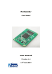
WIZ127SR User’s Manual (Version 1.11) © 2013 WIZnet Co., Ltd. All Rights Reserved. ☞ For more information, visit our website at http://www.wiznet.co.kr Document Revision History Date Revision Changes 2013-04-01 V1.00 Official Release 2013-07-04 V1.10 Add default setting value (4.4) Add CTS/RTS timing diagram (4.5) Modify some miss types Update Pin-Description(2.1) Update EVB-Schematic(2.4.1) 2013-09-25 V1.11 Add sentence “RS232 Level”(4.5) Information in this document is belived to be accurate and reliable. However, WIZnet does not give any representations or warranties, expressed or implied, as to the accuracy or completeness of such information and shall have no liability for the consequences of use of such information. WIZnet reserves the right to make changes to information published in this document, including without limitation specifictions and product descriptions, at any time and without notice. This document supersedes and replaces all information supplied prior to the publication hereof. WIZ127SR User’s Manual ii COPYRIGHT NOTICE Copyright 2013 WIZnet Co., Ltd. All Rights Reserved. Contact Information - WIZnet US : [email protected] / [email protected] - WIZnet HK : [email protected] - WUZnet EU : [email protected] - WIZnet HQ : [email protected] / [email protected] For more information, visit our website at http://www.wiznet.co.kr WIZ127SR User’s Manual iii Table of Contents 1. INTRODUCTION .......................................................................................................................... 1 1.1. 2. KEY FEATURE ............................................................................................................................... 1 HARDWARE SPECIFICATIONS ................................................................................................ 2 2.1. PIN ASSIGNMENT AND DESCRIPTION ........................................................................................... 2 2.2. DIMENSION ................................................................................................................................... 4 2.3. ELECTRICAL CHARACTERISTICS .................................................................................................. 5 2.3.1. Absolute Maximum Rating ................................................................................................ 5 2.3.2. DC Characteristics ............................................................................................................. 5 2.3.3. POWER DISSIPATION ..................................................................................................... 5 2.4. APPLICATION SCHEMATICS........................................................................................................... 6 2.4.1. WIZ127SR-BASE ............................................................................................................... 6 2.4.2. RS485/422 .......................................................................................................................... 7 3. PROGRAMMERS’ GUIDE .......................................................................................................... 8 3.1. SERIAL COMMANDS ...................................................................................................................... 8 3.1.1. Serial Command Format ................................................................................................... 8 3.1.2. Reply Code ......................................................................................................................... 8 3.1.3. Command Code ................................................................................................................. 8 3.2. DATA MODE AND COMMAND MODE ............................................................................................. 17 3.2.1. Data mode......................................................................................................................... 17 3.2.2. Serial Command mode ................................................................................................... 17 3.2.3. How to switch the mode .................................................................................................. 17 3.2.4. How to configure WIZ127SR with a whole data .......................................................... 17 3.2.4.1. Command Frame Format ........................................................................................... 18 3.2.4.2. Reply Frame Format .................................................................................................... 19 3.2.4.3. Example......................................................................................................................... 20 3.3. HOW TO GET THE SOCKET STATUS ............................................................................................. 21 3.4. HOW TO USE EXTRA GPIO PINS ................................................................................................ 21 4. HOW TO CONFIGURE WIZ127SR .......................................................................................... 22 4.1. CONFIGURING WITH UDP BROADCASTING AND WIZ127SR CONFIGURATION TOOL ............... 22 4.1.1. Network Configurations ................................................................................................... 22 4.1.2. Serial Configuration ......................................................................................................... 25 4.1.3. Option Configuration ........................................................................................................ 29 4.2. CONFIGURING WITH W EB BROWSER.......................................................................................... 31 4.3. CONFIGURING WITH TELNET ...................................................................................................... 32 4.4. FACTORY DEFAULT VALUES OF WIZ127SR .............................................................................. 34 4.5. HARDWARE FLOW CONTROL DIAGRAM (RS232 LEVEL) .......................................................... 36 4.5.1. CTS/RTS Mode Timing Diagram ................................................................................... 36 4.5.2. DTR/DSR mode Timing Diagram .................................................................................. 37 4.5.3. RTS Only mode Timing Diagram ................................................................................... 38 5. HOW TO UPLOAD A NEW FIRMWARE ................................................................................. 39 6. QUICK INSTALLATION AND TEST ........................................................................................ 42 6.1. SYSTEM CONFIGURATION .......................................................................................................... 42 6.2. TESTING PROCEDURE ................................................................................................................ 42 6.2.1. Hardware Connection...................................................................................................... 42 6.2.2. Module Configuration ...................................................................................................... 42 7. WARRANTY ............................................................................................................................... 47 WIZ127SR User’s Manual iv Figures FIGURE 1 PIN ASSIGNMENT ......................................................................................................................... 2 FIGURE 2 DIMENSION ................................................................................................................................... 4 FIGURE 3 WIZ127SR BASE BOARD SCHEMATIC......................................................................................... 6 FIGURE 4 REFERENCE SCHEMATIC FOR INTERFACING TO RS485/422 ...................................................... 7 FIGURE 5. CONFIGURATION TOOL (NETWORK CONFIGURATION) ............................................................. 22 FIGURE 6. CONFIGURATION TOOL (SERIAL CONFIGURATION) .................................................................. 25 FIGURE 7. CONFIGURATION TOOL (OPTION CONFIGURATION) ................................................................. 29 FIGURE 8. CTS SIGNAL TIMING DIAGRAM UNDER CTS/RTS MODE ......................................................... 36 FIGURE 9. RTS SIGNAL TIMING DIAGRAM UNDER CTS/RTS MODE ......................................................... 36 FIGURE 10. DTR SIGNAL TIMING DIAGRAM UNDER DSR/DTR MODE ....................................................... 37 FIGURE 11. DSR SIGNAL TIMING DIAGRAM UNDER DSR/DTR MODE ...................................................... 37 FIGURE 12. RTS SIGNAL TIMING DIAGRAM UNDER RTS ONLY MODE ...................................................... 38 FIGURE 13. CONFIGURATION TOOL ........................................................................................................... 39 FIGURE 14. OPEN DIALOG BOX FOR UPLOADING ....................................................................................... 40 FIGURE 15. FIRMWARE UPLOADING WINDOW ............................................................................................ 41 FIGURE 16. COMPLETE UPLOADING .......................................................................................................... 41 WIZ127SR User’s Manual v Tables TABLE 1 PIN DESCRIPTION........................................................................................................................... 3 TABLE 2 ABSOLUTE MAXIMUM RATING ........................................................................................................ 5 TABLE 3 DC CHARACTERISTIC .................................................................................................................... 5 TABLE 4 POWER DISSIPATION ...................................................................................................................... 5 TABLE 5. SERIAL CONFIGURATION FRAME FORMAT .................................................................................... 8 TABLE 6. SERIAL CONFIGURATION REPLY FRAME FORMAT ......................................................................... 8 TABLE 7. SERIAL CONFIGURATION STX & ETX .......................................................................................... 8 TABLE 8. SERIAL CONFIGURATION REPLY CODE ......................................................................................... 8 TABLE 9. HARDWARE CONFIGURATION FRAME FORMAT ........................................................................... 18 TABLE 10. HARDWARE CONFIGURATION COMMAND CODE....................................................................... 18 TABLE 11. HARDWARE CONFIGURATION PARAMETER DESCRIPTIONS ...................................................... 19 TABLE 12. HARDWARE CONFIGURATION REPLY FRAME FORMAT ............................................................. 19 TABLE 13. HARDWARE CONFIGURATION ENTRANCE MESSAGE ............................................................... 20 WIZ127SR User’s Manual vi 1. Introduction WIZ127SR is a 2 ports gateway module that converts RS-232 protocol into TCP/IP protocol. This module enables remote gauging, remote management of the device through the network based on the Ethernet and the TCP/IP by connecting to existing equipment with RS-232 serial interface. In other words, WIZ127SR is a protocol converter that transmits the data sent by serial equipment as TCP/IP data type or vice versa. 1.1. Key Feature - Plug & Play Type Serial to Ethernet Gateway module Adds Network Function Simply and Quickly Provides Firmware Customization - Hardware compatible with WIZ100SR - 2port serial to Ethernet supports RS-232 supports RS-422/485 by adding RS-232 to RS-422/485 converter - Supports TCP & UDP communication - Supports DHCP, DNS, NTP - Easy configuration Web, Telnet, Configuration Tool & Serial Command - GPIO Extendable (Max. 10GPIOs), by firmware customization - 10/100 Ethernet & Max.921,600bps Serial Interface - Supports Static IP, DHCP, PPPoE - Supports DNS function - RoHS compliant WIZ127SR User’s Manual 1 2. Hardware Specifications 2.1. Pin Assignment and Description VDD3V3 J3 PC14 PC15 UART2_CTS UART2_RTS UART2_TX UART2_RX STATUS2 PB11 PB12 PB13 PB14 PB15 1 2 3 4 5 6 7 8 9 10 11 12 VDD3V3A J1 1 2 3 4 5 6 7 8 9 10 11 12 RESET UART1_TX UART1_RTS PB0 UART1_RX UART1_CTS PB1 STATUS1 2.0mm HEADER 12x1 J2 1 2 3 4 5 6 7 8 9 10 11 12 2.0mm HEADER 12x1 RXIN RXIP TXON TXOP LINKLED_M0 PB5 SPDLED_M1 FDXLED_M2 VDD3V3 2.0mm HEADER 12x1 Figure 1 Pin Assignment Pin Location Pin name Description I/O J1.1 VDD3V3 3.3V Power Supply J1.2 RESET Reset (Active High) J1.3 GND Ground J1.4 UART1_TX TX Data Output for UART1 We recommend to add external pull-up resistor on UART1_TX. Output J1.5 UART1_RTS Request To Send for UART1 Output J1.6 PB0 GPIO pin Input/Output J1.7 GND Ground J1.8 UART1_RX RX Data Input for UART1 Input J1.9 UART1_CTS Clear To Send for UART1 Input J1.10 PB1 GPIO pin Input/Output J1.11 GND Ground Input Attribute - CMOS/TTL/5V tolerant Input CMOS/TTL/5V tolerant Input CMOS/TTL/5V tolerant Input WIZ127SR check whether this pin is asserted low as input pin during booting If it is low, WIZ127SR enter into Hardware configuration mode. Otherwise, It enters into normal mode J1.12 (*)STATUS1 High: Not connected Low: Connected J2.1 VDD3V3A Analog 3.3V Output J2.2 RXIN Ethernet Differential Input- Input - J2.3 RXIP Ethernet Differential Input+ Input - J2.4 GND J2.5 TXON Ethernet Differential Output- Output - J2.6 TXOP Ethernet Differential Output+ Output - J2.7 GND Ground J2.8 LINKLED_M0 Ethernet Link LED Output - J2.9 PB5 GPIO pin Input/Output WIZ127SR User’s Manual Input/Output CMOS/TTL/5V tolerant Input 2 J2.10 SPDLED_M1 Ethernet Speed LED Output - J2.11 FDXLED_M2 Ethernet Full-duplex LED Output - J2.12 VDD3V3 3.3V Power Supply J3.1 PC14 Input/Output CMOS/TTL/5V tolerant Input J3.2 PC15 Input/Output CMOS/TTL/5V tolerant Input J3.3 UART2_CTS Clear To Send for UART2 Input CMOS/TTL/5V tolerant Input J3.4 UART2_RTS Request To Send for UART2 Output CMOS/TTL/5V tolerant Input J3.5 UART2_TX TX Data Output for UART2 We recommend to add external pull-up resistor on UART2_TX. Output CMOS/TTL/5V tolerant Input J3.6 UART2_RX RX Data Input for UART2 Input CMOS/TTL/5V tolerant Input J3.7 STATUS2 High: Not connected Low: Connected Output CMOS/TTL/5V tolerant Input J3.8 PB11 Factory Reset (Active Low) Input CMOS/TTL/5V tolerant Input Factory Reset is done if it is asserted low during MCU booting. J3.9 PB12 GPIO pin Input/Output CMOS/TTL/5V tolerant Input J3.10 PB13 GPIO pin Input/Output CMOS/TTL/5V tolerant Input J3.11 PB14 GPIO pin Input/Output CMOS/TTL/5V tolerant Input J3.12 PB15 GPIO pin Input/Output CMOS/TTL/5V tolerant Input (*) This pin can be used for H/W Trigger (Active Low). Table 1 Pin Description WIZ127SR User’s Manual 3 2.2. Dimension Figure 2 Dimension WIZ127SR User’s Manual 4 2.3. Electrical Characteristics 2.3.1. Absolute Maximum Rating Symbol Parameter Rating Unit VDD DC Supply voltage -0.5 to 3.63 V VIN DC Input voltage -0.5 to 3.63 V IIN DC Input current 5 mA TOP Operating temperature 0 to 70 ℃ TSTG Storage temperature TBD ℃ Table 2 Absolute Maximum Rating 2.3.2. DC Characteristics Symbol VDD VIH Parameter Test Conditon Junction temperature is from -55℃ to 125℃ DC Supply voltage High level input voltage Min Max Unit 2.97 3.6 V 2.0 3.6 V 0.8 V VIL Low level input voltage 0.3 VOH High level output voltage 2.4 VOL Low level output voltage II Input Current Typ V VIN = VDD 0.4 V 5 μA Table 3 DC Characteristic 2.3.3. POWER DISSIPATION Test Condition(VCC3.3V, Temperature 25℃) Condition Min Typ Max Unit 100M Link - 200 215 mA 10M Link - 147 162 mA Loss Link - 158 173 mA 100M Transmitting - 200 215 mA 10M Transmitting - 147 162 mA Table 4 Power Dissipation WIZ127SR User’s Manual 5 2.4. Application Schematics WIZ127SR-BASE CONNECTOR ETHERNET STATUS 2.0 Pitch RXIN RXIP LINKLED_M0 TXON TXOP SPDLED_M1 LINKLED_M0 PB5 SPDLED_M1 FDXLED_M2 VDD3V3 FDXLED_M2 2.0mm HEADER 12x1 2.0 Pitch PB5 2.0 Pitch D1 330R LED R2 D2 330R LED R3 D3 330R LED R8 D4 330R LED C1 0.1uF 1 2 3 4 5 6 7 8 TXOP TXON RXIP RXIN 49.9R 2.0mm HEADER 12x1 VDD3V3A VDD3V3 R1 49.9R STATUS1 2.0mm HEADER 12x1 1 2 3 4 5 6 7 8 9 10 11 12 LINKLED_M0 9 10 SPDLED_M1 R9 330R R10 330R 11 12 VDD3V3 R7 UART1_RX UART1_CTS PB1 J2 49.9R TP4 UART1_TX UART1_RTS PB0 J1 R6 RESET TP3 RJ45 W\MAGNET VDD3V3A 1 2 3 4 5 6 7 8 9 10 11 12 49.9R J3 R4 VDD3V3 1 2 3 4 5 6 7 8 9 10 11 12 PC14 PC15 UART2_CTS UART2_RTS UART2_TX UART2_RX STATUS2 PB11 PB12 PB13 PB14 PB15 TP1 TP2 R5 2.4.1. 13 14 NC C2 0.1uF C3 0.1uF P1 TD+ TDTCT NC1 NC2 RCT RD+ RDL4L3+ L2L1+ CH_GND1 CH_GND2 RB1-105BAG1A GPIO IN/OUT VDD3V3 1 R12 2 3 R26 10K VDD3V3 VDD3V3 VDD3V3 SW3 SLD-SW 1 2 3 CONNECTED STATUS/HW TRIGGER PB14 10K 1 R15 2 3 R27 PB12 R13 330R D5 LED PB13 R14 330R D6 LED SW1 SLD-SW 10K 1 2 3 1 2 3 R11 UART1 0R C4 PB15 10K STATUS1 STATUS2 R19 D8 330R LED R20 D9 330R LED C5 0.1uF C6 0.1uF 1 U1 3 4 5 VDD3V3 C1+ VCC C1- V+ C2+ V- 16 2 C7 0.1uF 6 C8 0.1uF GND C2- 11 10 12 9 UART1_TX UART1_RTS UART1_RX UART1_CTS RESET VDD3V3 0.1uF VDD3V3 TIN1 TIN2 ROUT1 ROUT2 VDD3V3 C9 0.1uF TOUT1 TOUT2 RIN1 RIN2 GND 14 7 13 8 RS232_TX1 RS232_RTS1 RS232_RX1 RS232_CTS1 15 SP3232EUEY -L U2 R16 10K 1 2 1 4 SW4 TACT SW 3 C10 0.1uF NC VCC A Y R30 10K 5 4 FACTORY RESET RESET R29 10K UART1_TX UART2_TX VDD3V3 VDD3V3 GND SN74LVC1G14 C11 UART2 R25 10K 2 3 C12 R17 0.1uF 0R 1 4 C13 SW6 TACT SW UART2_TX UART2_RTS UART2_RX UART2_CTS 100R U4 AME8815BEGT330Z/SOT-223 2 VOUT 4 3 VIN VTAB 1 GND 3V3_IN 11 10 12 9 0R 0R 0R 0R VCC C1- V+ C2+ V- 16 2 C14 0.1uF 6 C15 0.1uF GND TIN1 TIN2 ROUT1 ROUT2 TOUT1 TOUT2 RIN1 RIN2 GND SP3232EUEY -L 14 7 13 8 RS232_TX2 RS232_RTS2 RS232_RX2 RS232_CTS2 P3 DB9_MALE-RA 5 9 4 8 3 7 2 6 1 15 TP5 C17 10uF/16V D7 LED VDD3V3 C18 10uF/16V M1 TH3.5 R18 330R M3 TH3.5 M4 TH3.5 TP6 1 2 3 4 5 6 UART2_TX UART2_RTS UART2_RX UART2_CTS VDD3V3A J5 2.54mm HEADER 6x1 1 TP8 M2 TH3.5 1 C16 10uF/16V TP7 R21 R22 R23 R24 C1+ 0.1uF C2- VDD3V3 L1 HH-1M1608-121JT 1 1 2 3 5V_IN 1 DC JACK 1 2 3 U3 4 5 SW5 TG-SW 1 2 3 J4 0.1uF C20 0.1uF 2 3 R28 1 3 PB11 NC POWER P2 DB9_MALE-RA 5 9 4 8 3 7 2 6 1 10 11 1 2 3 10 11 SW2 SLD-SW NC L2 HH-1M1608-121JT NC C19 10uF/16V Figure 3 WIZ127SR Base board schematic WIZ127SR User’s Manual 6 2.4.2. RS485/422 RS485 Example Circuit VDD3V3 0.1uF 1 UART2_RX 2 RO VCC RO B DE A 8 7 485- 1 2 UART2_RTS 3 4 UART2_TX DI 6 HEADER 2 120R 5 GND 485+ SP3485 RS422 Example Circuit VDD3V3 0.1uF 1 VCC A 2 UART2_RX 8 485_RX+ RO B 1 2 3 4 7 120R HEADER 4 485_RX- Z 3 UART2_TX 4 6 485_TX- 5 485_TX+ DI Y GND SP3701E Figure 4 Reference schematic for interfacing to RS485/422 WIZ127SR User’s Manual 7 3. Programmers’ Guide 3.1. Serial Commands 3.1.1. Serial Command Format It is possible to configure WIZ127SR by using serial command. By inputting specified 3 characters you can enter into the configuration mode. The characters can be defined at the Configuration Tool. < Frame Format > Command Frame format Descriptor STX Length(bytes) 1 Command code 2 Parameter Variable ETX 1 Table 5. Serial Configuration Frame format Reply Frame format Descriptor Length(bytes) STX 1 Reply code 1 Parameter Variable ETX 1 Table 6. Serial Configuration Reply Frame format STX & ETX Setting STX ETX Comments ‘<’ : Hex = 3Ch ‘>’ : Hex = 3Eh Table 7. Serial Configuration STX & ETX 3.1.2. Reply Code Reply S Comments Command was successful F 0 1 2 3 E Command failed Invalid STX Invalid command Invalid parameter Invalid ETX Enter Serial Command Mode Table 8. Serial Configuration Reply Code 3.1.3. Command WI Command Code Category Format Description <WIxxx.xxx.xxx.xxx> Set Local IP Meaning RI Response Format WIZ127SR User’s Manual ex) <WI192.168.11.133> <S> <RI> 8 Get the current WIZ127SR’s Local IP address Its response format is like below. <S[IP Addr]> Meaning [IP Addr] : Server’s IP address in a dotted decimal format WS Response Format ex) <RI> <S192.168.0.100> <WSxxx.xxx.xxx.xxx> Set Subnet Mark Meaning RS Response Format ex) <WS255.255.255.0> <S> <RS> Get the current WIZ127SR’s Subnet Mask Its response format is like below. <S[Subnet]> Meaning [Subnet] : Server’s IP address in a dotted decimal format WG Response Format ex) <RS> <S255.255.255.0> <WGxxx.xxx.xxx.xxx> Set Gateway Address Meaning RG Response Format ex) <WG192.168.11.1> <S> <RG> Get the current WIZ127SR’s Gateway address Its response format is like below. <S[IP Addr]> Meaning [IP Addr] : Server’s IP address in a dotted decimal format WP Response Format ex) <RG> <S192.168.0.1> <WPxxxxx> Set Local port number Meaning RP Response Format ex) <WP35000> <S> <RP> Get the current WIZ127SR’s Local port number Its response format is like below. <S[Port]> Meaning [Port] : Server’s IP address in a dotted decimal format ex) <RP> WD Response Format <WDx> Set the method of setting WIZ127SR’s IP address Meaning Parameter’s Value WIZ127SR User’s Manual Meaning 9 0 1 2 RD Response Format Static mode DHCP mode PPPoE mode ex) <WD0> or <WD1> <S> <RD> Get the current WIZ127SR’s method setting its IP address Its response format is like below. <S[Mode]> Meaning [Mode] : Server’s IP address in a dotted decimal format ex) <RD> WM Response Format <WMx> Set the operation mode of a TCP socket Parameter’s Value 0 Meaning Remarks TCP Client 1 TCP Mixed 2 TCP Server The TCP socket try to connect to the peer until the connection is established This mode is the same to TCP Server mode at first, but While any connection is not established, if WIZ127SR get any data via UART then WIZ127SR make TCP socket be a TCP Client socket and try to connect to the specified peer system. The TCP socket is in Listen mode waiting for a request of connection from any peer system. Meaning RM Response Format ex) <WM0> <S> <RM> Get the current data communication socket’s operation mode Its response format is like below. <S[Mode]> Meaning [Mode] : Server’s IP address in a dotted decimal format ex) <RM> WK Response Format <WKx> Set the protocol of the communication socket with one of two mode. Parameter’s Value Meaning 0 1 TCP UDP Meaning RK Response Format WIZ127SR User’s Manual ex) <WK0> <S> <RK> 10 Get the current data communication socket’s protocol type. Its response format is like below. <S[Protocol]> Meaning [Protocol] : Server’s IP address in a dotted decimal format ex) <RK> WB Response Format Meaning RB Response Format Meaning WT RT <WB[b][d][p][f]> Configure UART with four parameters [b], [d], [p] and [f] are a byte parameters, and those have the meaning as below Parameter Value Meaning [b] : baud rate c 921,600 bps b 460,800 bps a 230,400 bps 1 115,200 bps 2 57,600 bps 3 38,400 bps 4 19,200 bps 5 9,600 bps 6 4,800 bps 7 2,400 bps 8 1,200 bps [d] : data bits size 7 7 bits 8 8 bits 9 9 bits [p] : parity 0 No Parity 1 Odd Parity 2 Even Parity [f] : flow control 0 None 2 RTS/CTS 3 DSR/DTR 4 RTS Only (For RS485) ex) <WB1800> => 115200, 8 bits, no parity, no flow control <S> <RB> Get the current configuration information of WIZ127SR’s serial interface. Its response format is like below. <S[baud rate][data size][parity][flow control]> Response Format ex) <RB> <S1800> <WT[y]> Set whether serial command will be allowed, or not Meaning [y] = 0 : Disable [y] = 1 : Enable Response Format Meaning WIZ127SR User’s Manual ex) <WT1> <S> <RT> Get the current setting of serial command method 11 Its response format is like below. <S[Option]> [Option] : Server’s IP address in a dotted decimal format WU RU Response Format ex) <RT> <S1> <WU[y]> Set Whether DNS service will be allowed Meaning [y] = 0 : Not use [y] = 1 : Use Response Format ex) <WU1> <S> <RU> Get whether DNS mode is enabled or not Its response format is like below. <S[flag]> Meaning [flag] : 0 = Not Use, 1 = Use WE Response Format Meaning RE Response Format Meaning ex) <RU> <S1> <WE[ch][ch][ch]> Set character string using for Software trigger in order to enter serial command mode. [ch] is a ASCII character represented in its hexadecimal format. For example, if user wants use ‘A’ as [ch] then user should input its ASCII code in hexadecimal format, ‘4’ and ‘1’, not ‘A’. ex)If character string for software trigger is “+++” then <WE2B2B2B> <S> <RE> Get the current character string for software trigger to enter the serial command mode. Its response format is like below. <S[ch1][ch2][ch3]> [IP Addr] : Server’s IP address in a dotted decimal format WX Response Format ex) <RE> <S2B2B2B> <WX[IP Addr]> Set Server’s IP address to connect when the data socket is defined as Client mode or Mixed mode. If user defined the data socket as a Server mode, WIZ127SR don’t care this Server’s IP address. Meaning [IP Addr] : Server’s IP address in a dotted decimal format RX Response Format Meaning WIZ127SR User’s Manual ex) <WX192.168.11.144> <S> <RX> Get the current Server’s IP address 12 Its response format is like below. <S[IP Addr]> [IP Addr] : Server’s IP address in a dotted decimal format WN Response Format Meaning RN Response Format ex) <RX> <S192.168.0.115> <WN[port]> Set Server’s port number to connect when the data socket is defined as Client mode or Mixed mode. [port] : Server’s port number in a decimal format. Its range is 0 to 65535 ex) <WN5000> <S> <RN> Get the current Server’s Port number Its response format is like below. <S[Port number]> Meaning [IP Addr] : Server’s IP address in a dotted decimal format WR Response Format Meaning WV Response Format Meaning ex) <RN> <S5000> <WR> Restart WIZ127SR Some commands need reboot of WIZ127SR in order that those command affect to WIZ127SR’s configuration to operate properly. So, we recommend you do use this command after all command you issued, to guarantee WIZ127SR operate successfully. ex) <WR> <S> <WV[IP addr]> Set Domain Name Server’s IP address If you want to use Server information in Domain name, not IP address, then you should set Domain Name Server’s IP address using this command. And the Domain Name Server’s IP address which you entered should be valid and operate DNS query successfully. [IP Addr] : Server’s IP address in a dotted decimal format RV Response Format <WV8.8.8.8> <S> <RV> Get the current Domain Name Server IP address Its response format is like below. <S[IP Addr]> Meaning [IP Addr] : Server’s IP address in a dotted decimal format WW Response Format WIZ127SR User’s Manual ex) <RV> <S8.8.8.8> <WW[Domain name]> 13 Meaning Set Domain Name which you connect to. This information is meaningful as if you want use the data socket as Client mode or Mixed mode and set DNS enabled and set a proper DNS IP address. If one of them isn’t set properly, despite you use this command, you can’t get a good response. [Domain name] : Domain name in string type RW WY RY Response Format ex) <WWwww.google.com> <S> <RW> Meaning Get the current Domain Name set in WIZ127SR Its response format is like below <S[Domain Name]> Response Format Meaning Response Format Meaning WZ RZ Response Format Meaning Response Format [Domain Name] <Swww.wiznet.co.kr> <WY[ID]> Set ID for PPPoE authentication <S> <RY> Get the current ID for PPPoE Its response format is like below <S[ID]> [ID] : <Sadmin> <WZ[Passwd]> Set Password for PPPoE authentication <S> <RZ> Get the current password for PPPoE Its response format is like below. <S[Passwd]> Meaning [Passwd] : Server’s IP address in a dotted decimal format OC Response Format Meaning ex) <RZ> <Sadmin> <OC[ch]> 1 Set a character delimiter for making a ethernet data block in Hexadecimal format. [ch] : character information. Default value is 00. If this value is 00, it means Character Delimiter disabled 1 In normal, a serial device send data in chunk. Some device never expects those data chunk would be divided more than two pieces. But WIZ127SR handle data from serial interface byte by byte, in other word WIZ127SR check its serial buffer having data from serial interface and there are some data in that buffer, then it make a ethernet packet with those data and send that. But because the peer system expects all data chunk, that consider those data was broken and discard those. So, to avoid this fault, WIZ127SR provides three scheme to handle serial data chunk by chunk. Those are character delimiter, size delimiter and time delimiter. WIZ127SR User’s Manual 14 QC Response Format ex) <OC1B> <S> <QC> Get the current character delimiter Its response format is like below. <S[ch]> Meaning [ch] : Server’s IP address in a dotted decimal format OS Response Format Meaning QS Response Format ex) <QC> <S41> <OS[size]> Set a size delimiter for making a ethernet data block in Decimal format [size] : size information. Its range is 0 ~ 255. Default value is 0. If this value is 0, it means Size Delimiter Disabled ex) <OS100> <S> <QS> Get the current size delimiter value Its response format is like below. <S[size]> Meaning [size] : Server’s IP address in a dotted decimal format OT Response Format Meaning QT Response Format ex) <QS> <S40> <OT[time]> Set a time delimiter for making a ethernet data block in Decimal format [time] : time information. Its range is 0 ~65535. Unit is millisecond. Default value is 0. If this value is 0, it means Time Delimiter disabled ex) <OT100> <S> <QT> Get the current time delimiter value Its response format is like below. <S[time]> Meaning [time] : Server’s IP address in a dotted decimal format OI Response Format WIZ127SR User’s Manual ex) <QT> <S100> <OI[time]> 15 2 Set the inactivity time for disconnecting the current established socket, as data communication is idle for some time which users already set Meaning QI Response Format [time] : time information. Its range is 0 ~65535. Unit is second. Default value is 0. If this value is 0, it means Inactivity Time disabled <S> <QI> Get the current inactivity time value Its response format is like below. <S[time]> Meaning [time] : Server’s IP address in a dotted decimal format RA Response Format ex) <QI> <S60> <RA> Get the current MAC address of WIZ127SR Its response has a format like below. <S[MAC Addr]> Meaning RF Response Format [MAC addr] : This is 6 ASCII String in a Hexadecimal format with delimiters, ‘:’, following to every 2 characters. ex) <RA> <S00:08:DC:00:11:22> <RF> Get the current firmware version stored in WIZ127SR. Its response format is like below. <S[Ver]> Meaning [Ver] : Server’s IP address in a dotted decimal format Response ex) <RF> <S3.1> 2 WIZ127SR itself doesn’t disconnect a TCP connection after a connection established. Normally the peer system do that. But, there are many cases that users’ system including WIZ127SR should close a established connection after a short data communication and any peer system of WIZ127SR doesn’t have those capabilities. Inactivity time scheme is a useful function under this circumstance. If WIZ127SR doesn’t receive any data from the serial interface during the time set as the Inactivity Time, then WIZ127SR closes the current established connection itself. But If any character is entered from the serial interface before the Inactivity Time timer is expired, the timer will be reinitialized. WIZ127SR User’s Manual 16 3.2. Data mode and Command mode WIZ127SR has two operation mode - serial command mode and data mode through serial interface. These are concerned to the communication between host processor and WIZ127SR. 3.2.1. Data mode Data mode is the default mode of WIZ127SR. After booting, WIZ127SR operates itself as ‘Serial to Ethernet; converter. It tries to connect or listens to get peer’s connection request. During this mode, WIZ127SR holds the data from host processor via serial interface as just data. If the connection is already established, WIZ127SR transmits the data to peer system, and also receives data which are sent by the peer from Ethernet. In other words, WIZ127SR transparently bypasses data from Ethernet to serial interface and vice versa without editing those data. 3.2.2. Serial Command mode In serial command mode, WIZ127SR treats data from host processor as a command. If the command is valid, it sends a proper response. If not it responds with error message. In the serial command mode, there is no data communications between WIZ127SR and peer system. If WIZ127SR enters into serial command mode, it will print out “<E” message through serial interface to inform host processor that it successfully entered into serial command mode. But when it switches to data mode, it doesn’t print out any message. 3.2.3. How to switch the mode There is a method to switch the mode from data to serial or vice versa. That is using the software triggering. Software triggering Host processor can make WIZ127SR enter into serial command mode by issuing software triggering string, which is already set by user through serial interface. User can set this string by the configuration tool, web config page or telnet. In order to escape from serial command mode, host processor just issues <WR> command. Then, WIZ127SR reboots and operates as data mode. 3.2.4. How to configure WIZ127SR with a whole data As User wants to configure WIZ127SR in one time operation, he can do it using handling the Hardware trigger pin. If you supply the power or reset the module with asserting low on pin 12 of JP1, you can WIZ127SR User’s Manual 17 configure the module using special serial commands. At this mode, network configuration or data communication is not allowed. Therefore, after finishing the configuration, be sure to assert high on pin 12 of JP1 for normal operation. 3.2.4.1. Command Frame Format Frame Format Descriptor Length(bytes) Format STX 1 ‘>’(0x3E) Command codes 1 R/W/X Parameter Variable Variable ETX 1 ‘CR’(0x0D) Table 9. Hardware Configuration Frame format Command Codes Command R W X E Comments Read Parameter Write Parameter Exit Hardware Command mode Command Error Table 10. Hardware Configuration Command Code Parameter Structure Value(bytes count) Description 0008DCxxxxxx(6) MAC address (xxxxxx is uniquely factory set) 01 (1) Mode (00: TCP Client, 01 : TCP Mixed, 02 : TCP Server) 00000000 (4) IP address 00000000 (4) Subnet mask 00000000 (4) Gateway address 0000 (2) Local Port number (Module's Port Number) 00000000 (4) Server IP address 0000 (2) Server Port number Serial Baud Rate (bps). Default is FE FE (1) WIZ127SR User’s Manual Value(Hex) Baud Rate(bps) BB 230,400 FF 115,200 FE 57,600 FD 38,400 FA 19,200 F4 9,600 E8 4,800 D0 2,400 A0 1,200 18 08 (1) Serial data size (08: 8 bit), (07: 7 bit) 00 (1) Parity (00: No), (01: Odd), (02: Even) 01 (1) Stop bit 00 (1) Flow control (00: None), (01: XON/XOFF), (02: CTS/RTS) 00 (1) Delimiter character 0000 (2) Delimiter size 0000 (2) Delimiter time 0000 (2) Delimiter inactivity time 00 (1) Debug code (00: ON), (01: OFF) 03 (1) Software major version 01 (1) Software minor version 00 (1) DHCP option (00: DHCP OFF, 01:DHCP ON) 00 (1) UDP mode (00: TCP; 01: UDP) 00 (1) Connection Status (00:not connected, 01: connected) 00 (1) DNS Flag (00:not use DNS, 01:use DNS) 00000000 (4) DNS Server IP address 00……00 (32) Server Domain Name 00 (1) Serial command method(00:disable, 01:enable) 2B2B2B (3) Serial command mode character(Hex) 002020……2020 (32) PPPoE ID 002020……2020 (32) PPPoE Password 00 (1) Password option for TCP Server (00:disable, 01:enable) 0000000000000000 (8) Password for TCP Server FF Last Byte (It means end of parameter) Table 11. Hardware Configuration Parameter descriptions 3.2.4.2. Reply Frame Format Frame Format Descriptor Length(bytes) Command STX 1 ‘<’(0x3C) Reply code 1 S Parameter Variable Variable ETX 2 ‘CR’’LF’(0x0D0A) Table 12. Hardware Configuration Reply Frame format Reply for Entrance Hardware Command Mode (Hex : 0x3B) [Normal mode] ; [Debug mode] WIZ127SR bootloader Ver. 1.0 WIZ127SR User’s Manual 19 Firmware Ver. 0.9 ; Table 13. Hardware Configuration Entrance Message 3.2.4.3. Example Reading Parameter STEP 1. Supply the power into the module by asserting low pin 12 pin of JP1. STEP 2. Check if the reply message (‘;’) is displayed to notify whether WIZ127SR entered into Hardware Configuration. If module is set as ‘Debug mode’, the message is displayed after showing its model name and version. WIZ127SR bootloader Ver. 1.0 Firmware Ver. 0.9 ; ( <= This is the notification message) STEP 3. Input ‘>R’ and Carriage Return(0x0D). STEP 4. Check response message. WIZ127SR bootloader Ver. 1.0 Firmware Ver. 0.9 ;<S0008DC135E2401C0A80B03FFFFFF00C0A80B011388C0A80B011388FE08000100000000 0000000000030100000000000000000020202020202020202020202020202020202020202020 202020202020202020012B2B2B0020202020202020202020202020202020202020202020202 0202020202020200020202020202020202020202020202020202020202020202020202020202 020000000000000000000FF Changing IP Address When changing the parameter value, the MAC address is not changed. As MAC address is the unique value for the module, user can’t change it. When changing the IP address, input the new value after first 6bytes. STEP 1. Check HEX value of new IP address. In here, the new IP address is assumed as ‘192.168.11.10’. Therefore, the hex value ‘C0A80B0A’ is input. STEP 2. Input ‘>W01C0A80B0AFFFFFF00 … 00FF’. STEP 3. Check ‘<S’ message is displayed. After displaying this message, CR(0x0D) & LF(0x0A) are displayed together. STEP 4. After completing the change, check if changed value is appropriated saved by using READ command. WIZ127SR User’s Manual 20 3.3. How to get the socket status In order to get the current status of its corresponding sockets, user can monitor its STATUS pin. There are two pins for this function in WIZ127SR. One, STATUS1, is pin 12 of JP1 and the other, STATUS2, is pin 7 of JP3. STATUS1(pin 12 of JP1) pin shares the function of Hardware trigger for configuration of WIZ127SR. STATUS1 is operating as input for checking whether user makes to enter it into Hardware trigger mode during booting of WIZ127SR and after booting, WIZ127SR change STATUS1 pin to output port and this pin notifies what the current status of UART0’s corresponding socket is. As this pin operates as output pin, if its value is LOW, its corresponding socket is disconnected. Otherwise, the connection of the socket is established. STATUS2 pin is only to notify whether its corresponding socket is connected or not. The meaning of its signal value is the same to STATUS1. 3.4. How to use extra GPIO Pins WIZ127SR has extra GPIO pins using to control other devices or get control from other devices. But, with firmware version 0.9, WIZ127SR doesn’t support this function yet. WIZ127SR User’s Manual 21 4. How to configure WIZ127SR 4.1. Configuring with UDP broadcasting and WIZ127SR Configuration Tool 4.1.1. Network Configurations Figure 5. Configuration Tool (Network Configuration) 1) Search The Search function is used to search for all existing modules on the same LAN. By using UDP broadcast, it finds all modules on the same subnet, and the founded device will be listed in the “Serial to Ethernet” tree(Search Window) with its MAC address. 2) Setting This function is to apply your configurations. When you select the MAC address from the “Search Window”, the default value of the module will be displayed. Modify your configurations and click “Setting” button to apply your settings. The module will re-initialize and save the changed configurations. You can change the configurations by following steps: ① Select the MAC address of the device which you would like to modify in the “Search WIZ127SR User’s Manual 22 Window” ② Modify the settings according to your needs ③ Click the “Setting” button to apply your settings ④ The module will be initialized by a re-booting process ⑤ To verify your settings, please click ‘Search’ button and view your new settings 3) Firmware Upload Firmware will be uploaded through your network. The Procedure of Firmware upload is explained details in “5. How to upload a new firmware” 4) Factory Reset All setting value is initialized to factory default, if you click the “Factory Reset” button. For factory default value of WIZ127SR, refer to “4.4 Factory Default Value of WIZ127SR” 5) Exit Close the configuration tool program window. 6) Search Window If you click the “Search” button, all the MAC addresses on the same subnet will be displayed. 7) Device network settings Static: “Using the follow IP Address” is an option for setting WIZ127SR module’s IP with static IP address.. 1. Select a MAC address which you want to set as static IP in the “Search Window”. 2. Check “Using the follow IP address”. 3. The “Device IP, Gateway, Subnet mask, DNS server” box will be enabled, and then input address in those fields. 4. Click the “Setting” button to apply your configurations. DHCP: Select “Get IP address from DHCP server” option to use the DHCP mode. 1. Select the MAC address on the “Search Window”. 2. Check “Get IP address from DHCP server” and click the ‘Setting’ button. 3. A module will acquire network information from the DHCP server. (Should wait a moment to acquire network information from the DHCP server.) 4. When a module on the “Search Window” is selected, the IP address, Subnet mask and Gateway are displayed. If the module could not acquire the network information from the DHCP server, the IP address, the Gateway Address and the Subnet mask will be initialized as 0.0.0.0. IP Address Information WIZ127SR User’s Manual 23 ☞ Device IP: WIZ127SR’s IP Address Gateway: WIZ127SR’s Gateway Address Subnet mask: WIZ127SR’s Subnet Mask DNS server: DNS Server’s IP Address If you are unclear about your Local IP, Subnet Mask, Gateway information, you have to get this information from your network administrator. If the IP address is not correct, IP collision or network problems may occur. 8) F/W Version It displays the firmware version. 9) Enable Serial Debug Mode If this mode is enabled, you can monitor the status and socket messages of WIZ127SR through the serial terminal (listen OK, connect fail and etc.). In this mode, debug messages can cause abnormal operation of the serial device. Therefore, you should use this mode only for debugging. 10) Network Status This field shows the Connection Status of UART0 and UART1 in WIZ127SR. The message “Connected” will be displayed when a peer successfully connects to WIZ127SR. WIZ127SR User’s Manual 24 4.1.2. Serial Configuration Figure 6. Configuration Tool (Serial Configuration) You should set to UART configuration after checking UART tab whether it is UART0 or UART1. The numbers on the screenshot correspond to the descriptions listed below. 1) COM port setting This menu is used for setting the serial port. ☞ In order to apply your settings, click the “Setting” button 2) Working mode Client / server / mixed: This is to select the communication method based on TCP. TCP is the protocol to establish the connection before data communication, but UDP just processes the data communication without connection establishment. The Network mode of WIZ127SR can be divided into TCP Server, TCP Client and Mixed mode according to the connection establishing method. At the TCP server mode, WIZ127SR operates as server on the process of connection, and waits for the connection trial from the client. WIZ127SR operates as client at the TCP Client mode on the process of connection, and tries to connect to the server’s IP and Port. Mixed WIZ127SR User’s Manual 25 modes supports both of Server and Client. The communication process of each mode is as below. TCP server mode Communication At the TCP Server mode, WIZ127SR waits for the connection requests. TCP Server mode can be useful when the monitoring center tries to connect to the device (where WIZ127SR is installed) in order to check the status or provide the commands. In normal time WIZ127SR is on the waiting status, and if there is any connection request (SYN) from the monitoring center, the connection is established (ESTABLISH), and data communication is processed (Data Transaction). Finally connection is closed (FIN). In order to operate this mode, “Device IP”, “Subnet mask”, “Gateway” and “Local port” should be configured first. The Data transmission proceeds as follows, 1. The host connects to the WIZ127SR which is configured as TCP Server mode. 2. As the connection is established, data can be transmitted in both directions – from the host to the WIZ127SR, and from the WIZ127SR to the host TCP client mode Communication If WIZ127SR is set as TCP Client, it tries to establish connection to the server. To operate this mode, “Device IP”, “Subnet mask”, “Gateway”, “Remote host”, and “Remote port” should be set. If “Remote host” has domain name, you should be confirmed the “DNS server” field. In TCP Client mode, WIZ127SR can actively establish a TCP connection to a host computer when power is supplied. The Data transmission proceeds as follows: 1. As power is supplied, WIZ127SR board operating as TCP client mode actively establishes a connection to the server. 2. If the connection is complete, data can be transmitted in both directions – from the host to the WIZ127SR and from WIZ127SR to the host Mixed mode Communication In this mode, WIZ127SR normally operates as TCP Server and waits for the connection request from the peer. However, if WIZ127SR receives data from the serial device before connection is established, it changes to the client mode and sends the data to the server IP. Therefore, at the mixed mode, the server mode is operated prior to the client mode. As like TCP Server mode, the Mixed mode is useful for the case that the monitoring center tries to connect to the serial device (in which WIZ127SR is used) to check device status. In addition WIZ127SR User’s Manual 26 to this, if any emergency occurs in the serial device, the module will change to Client mode to establish the connection to the server and deliver the emergency status of the device. UDP mode Communication UDP is not a connection oriented protocol. But the communication port should also be defined well. If the UDP mode is selected, the data from serial interface can be defined where to delivery via the “Remote host” and “Remote port”, and the WIZ127SR can also be defined where to receive Ethernet data from via the “Remote host” and “Local port” definition. If the data destination and source are the same, the two IP address will also be the same. Please note the destination and source are using the same port. 3) Communication When your module is set as “Client mode”, “Mixed mode” or “UDP mode”, peer IP and port should be set in order for WIZ127SR to connect to the server(or peer). ☞ Local port: This field is to set the network port number in WIZ127SR. You should set to different port number from each other UART port. Remote port: This field is to set the network port number in remote device. Remote host: This field is to set the network address. (IP address or Domain name) of remote device. If your application needs the DNS function, input the domain name of connecting node (E.g.: www.wiznet.co.kr) into “Remote host” field and the DNS Server IP address into “DNS server” field. Domain Name System (DNS) is a database system that associates the Domain name with the actual IP address. The purpose of the DNS system is to resolve the Domain name and represent it as an IP address. As a result, your device can connect to an actual IP address. 4) Timers Nagle wait time: Normally, Data which received from UART are sent to Ethernet immediately. But in many case, user want to send data as a chunk of the whole frame without separated ones. This option is for packetizing data to one frame. Ordinarily there is some delay between one frame of data and the next one. This field is for specifying time value to judge whether one frame is received totally. If the time specified in this field is expired after receiving one byte, then WIZ127SR notice one data frame WIZ127SR User’s Manual 27 is finished, make an Ethernet packet with all data in its serial buffer and send it to the peer system via Ethernet. If WIZ127SR receives another byte from UART before the specified time is expired, it restart timer and add the received one to the end of serial data buffer. (‘0’: Function Disable) Inactivity: When there is no data transmission, the connection will be closed automatically after the time specified in the Inactivity time. If the default value ‘0’ is set as the Inactivity time, the network connection is maintained even though there is no data transmission. In order to close the connection, you should use the ‘Close’ commands. This function is useful when you have two or more systems which are connected to the WZ127SR module. When one system is connected to the WIZ127SR, other systems cannot connect to the module simultaneously. If you defined a time in the Inactivity time, the other system can connect to the module after the inactivity time elapsed. Inactivity Time can also be used when the server system is unexpectedly shut down. In this case, there will not be any data communication. After the time defined in the Inactivity time elapsed, WIZ127SR will close the connection and enter into waiting state. Reconnection: The connection retry interval. (Client mode only) 5) Serial Configuration This function is for module configuration not through network with configuration tool, web configuration and telnet but through serial communication. At the default status, the serial command mode is disabled. When you want to set WIZ127SR via serial communication, check “enable”. WIZ127SR User’s Manual 28 4.1.3. Option Configuration Figure 7. Configuration Tool (Option Configuration) You should set to UART configuration after checking UART tab whether it is UART0 or UART1. The numbers on the screenshot correspond to the descriptions listed below. 1) Device name The device name is displayed in this area. 2) Serial number The serial number of device is displayed in this area. 3) Password The password that is used for web configuration and telnet is displayed in this area. The shown password is encrypted by MD5. If you want to change the password, double-click the text-box and then type your password in ASCII codes. WIZ127SR User’s Manual 29 4) NTP NTP(Network Time Protocol) is a protocol for clock synchronization between computer systems over the networks. This function is reserved for customization. In case of standard version, this function just working for clock synchronization and display the time to configuration tool and web page. Enable NTP: This check-box is to set the enable/disable of NTP. NTP Server IP: This field is to set the NTP server IP address. Device Time: This field is to shown the current time of WIZ127SR. Time Zone: This field is to set the time zone of your country. WIZ127SR User’s Manual 30 4.2. Configuring with Web browser Open the web browser and input the IP address of the module. The first page will request the user password as shown in below figure. If you input the password (the default value is WIZ127SR), the configuration page will be displayed. You can set the configuration parameters of network and serial. WIZ127SR User’s Manual 31 4.3. Configuring with Telnet You can configure the WIZ127SR by using Telnet Client(*) program. If you connect to the WIZ127SR, you can see the message of requesting user password. Input the user password (Default P/W : WIZ127SR). You can see the message “Press ‘Q’ to enter the main console menu”. If you input the ‘Q’, the main menu for the WIZ127SR configuration is displayed. WIZ127SR User’s Manual 32 (*) You can use the Telnet client program which is provided by Windows OS. At the Windows XP, you can use the Telnet client program without additional setting. However at the Windows Vista or above version, you must enable the Telnet Client program first. For the detail, refer to the site http://goo.gl/Plhyu. WIZ127SR User’s Manual 33 4.4. Factory Default Values of WIZ127SR Category Common UART0 UART1 WIZ127SR User’s Manual Item Value Debug Message Enable 1 (Enable) DHCP Enable 0 (Disable) Local IP 192.168.11.100 Gateway IP 192.168.11.1 Subnet mask 255.255.255.0 DNS Server IP 8.8.8.8 Password WIZ127SR Device Name WIZ127SR NTP Enable 0 (Disable) NTP Server IP 128.138.140.44 Time Zone 40) UTC+09:00 Serial Configure Enable 0 (Disable) Serial Configure Trigger 0x2b 0x2b 0x2b (“+++”) Working Mode TCP mixed Local Port 5000 Remote Server IP 192.168.11.101 Remote Server Port 5001 Baudrate 115200 Data bit 8 Parity NONE Stop Bit 1 Flow Control NONE DNS Enable 0 (Disable) Domain - Nagle Time 0 (ms) Inactivity Time 10 (seconds) Reconnection Time 1000 (ms) Working Mode TCP mixed Local Port 5001 Remote Server IP 192.168.11.101 Remote Server Port 5002 Baudrate 115200 Data bit 8 Parity NONE 34 WIZ127SR User’s Manual Stop Bit 1 Flow Control NONE DNS Enable 0 (Disable) Domain - Nagle Time 0 (ms) Inactivity Time 10 (seconds) Reconnection Time 1000 (ms) 35 4.5. Hardware Flow Control Diagram (RS232 Level) 4.5.1. CTS/RTS Mode Timing Diagram Send(CTS) CTS Start Do not send Tx 7 bits Data 7 bits Data 7 bits Data Check CTS It is fine to send Yes Send a byte Is there any data to send? CTS No Tx 8 bits Data 8 bits Data 8 bits Data End CTS Tx 9 bits Data 9 bits Data 9 bits Data Figure 8. CTS signal Timing Diagram under CTS/RTS mode Receive(RTS) RTS Start Receive and store a byte Buffer will be to buffer overflow Buffer is free Rx 7 bits Data 7 bits Data 7 bits Data Check Buffer Set RTS to HIGH Set RTS to LOW RTS Rx 8 bits Data 8 bits Data 8 bits Data End RTS Rx 9 bits Data 9 bits Data 9 bits Data Figure 9. RTS signal Timing Diagram under CTS/RTS mode WIZ127SR User’s Manual 36 4.5.2. DTR/DSR mode Timing Diagram DTR (Data Terminal Ready) DTR Start Do not send Tx 7 bits Data 7 bits Data 7 bits Data Check DTR It is fine to send Yes Send a byte DTR Is there any data to send? Tx 8 bits Data 8 bits Data 8 bits Data No End DTR Tx 9 bits Data 9 bits Data 9 bits Data Figure 10. DTR signal timing diagram under DSR/DTR mode DSR (Data Set Ready) DSR Start Rx Device Initialize Yes Successful Initialize? Set DSR to HIGH 7 bits Data 7 bits Data 7 bits Data No Set DSR to LOW DSR Rx 8 bits Data 8 bits Data 8 bits Data End DSR Rx 9 bits Data 9 bits Data 9 bits Data Figure 11. DSR signal Timing Diagram under DSR/DTR mode WIZ127SR User’s Manual 37 4.5.3. RTS Only mode Timing Diagram Send(RTS Only) RTS Start Set RTS to LOW Tx 7 bits Data 7 bits Data 7 bits Data Send a byte Yes Is there any data to send? RTS No Set RTS to HIGH Tx 8 bits Data 8 bits Data 8 bits Data End RTS Tx 9 bits Data 9 bits Data 9 bits Data Figure 12. RTS signal Timing Diagram under RTS only mode WIZ127SR User’s Manual 38 5. How to upload a new firmware Run “WIZ127SR Configuration Tool” program, and click the “Search” button. If the module is properly connected to the network, the MAC address will be displayed on the “Search Window” as shown in Figure 4. Figure 13. Configuration Tool Select a module shown in the “Search Window”, and click the “Firmware Upload” button. ☞ Before uploading the firmware through Ethernet, you should set the network information of WIZ127SR first, by Configuration Tool program as shown above in Figure 4. By using Ping test, you can check whether your network is configured correctly or not. When the window as shown in Figure 5 is displayed, select file to upload and click the “Open” button. WIZ127SR User’s Manual 39 Figure 14. Open dialog box for uploading ☞ Do not upload any other files except for WIZ127SR application firmware file. WIZ127SR User’s Manual 40 The progress bar will be displayed as below. Figure 15. Firmware uploading window When uploading is completed, a message box with “Firmware download over” will be displayed as shown in Figure 7. Figure 16. Complete Uploading WIZ127SR User’s Manual 41 6. Quick Installation and Test In this chapter, we will provide a example for you to learn how to install and test “Serial to Ethernet” data communication with the WIZ127SR. 6.1. System Configuration Serial Cable Configuration Tool Ethernet Cable PC Terminal Program WIZ127SR-EVB Hardware PC having a RS-232 serial port and Ethernet port WIZ127SR & WIZ127SR Base Board Ethernet Cable (Direct or Crossover Cable) Software WIZ127SR Configuration Tool Hyper Terminal 6.2. Testing Procedure 6.2.1. ① Hardware Connection Connect the PC and WIZ127SR base board (in which the module is plugged) with serial cable ② Connect the PC and WIZ127SR base board by using Ethernet cable. ③ Supply the power to the test board. 6.2.2. ① Module Configuration In this manual, we are going to test the module with following configuration. Category Network Configuration WIZ127SR User’s Manual Parameters IP Address 192.168.11.100 Subnet 255.255.255.0 42 Gateway 192.168.11.1 Local port 5000 Baud Rate 115,200 Data bit 8 Parity None Stop bit 1 Flow Control None COM Port setting Working mode ② TCP server Check the network configuration of the PC and set the appropriate value. Both of module and PC should be in the same network. Therefore, the IP address of the PC should be 192.168.11.xxx with the subnet 255.255.255.0. ③ Execute the configuration tool program and search the module. Set the all parameters as indicated in WIZ127SR User’s Manual 43 WIZ127SR User’s Manual 44 ④ Check the COM port status of the PC and open the serial terminal. ⑤ Check the IP Address and port of WIZ127SR and connect to WIZ127SR. WIZ127SR User’s Manual 45 ⑥ If you input some characters at the windows of serial, you can see they are displayed in the TCP window. ⑦ Vice versa, type some characters in the windows of TCP Client, you can see the characters are displayed in the serial Windows. WIZ127SR User’s Manual 46 7. Warranty WIZnet Co., Ltd offers the following limited warranties applicable only to the original purchaser. This offer is non-transferable. WIZnet warrants our products and its parts against defects in materials and workmanship under normal use for period of standard ONE(1) YEAR for the WIZ127SR board and labor warranty after the date of original retail purchase. During this period, WIZnet will repair or replace a defective products or part free of charge. Warranty Conditions: The warranty applies only to products distributed by WIZnet or our official distributors. The warranty applies only to defects in material or workmanship as mentioned above. The warranty applies only to defects which occur during normal use and does not extend to damage to products or parts which results from alternation, repair, modification, faulty installation or service by anyone other than someone authorized by WIZnet Co., Ltd. ; damage to products or parts caused by accident, abuse, or misuse, poor maintenance, mishandling, misapplication, or used in violation of instructions furnished by us ; damage occurring in shipment or any damage caused by an act of God, such as lightening or line surge. Procedure for Obtaining Warranty Service Contact an authorized distributors or dealer of WIZnet Co., Ltd. for obtaining an RMA (Return Merchandise Authorization) request form within the applicable warranty period. Send the products to the distributors or dealers together with the completed RMA request form. All products returned for warranty must be carefully repackaged in the original packing materials. Any service issue, please contact to [email protected] WIZ127SR User’s Manual 47