1
Technical Instructions
Document Number 155-055P25
April 1, 2005
Specifications
SW 151 Positioning Switch
Output:
Standard
Operating
Bleed
Capacity
Medium Air
Ambient Temperature
Physical
Maximum Air Pressure
Air Consumption
(151-143)
(151-142)
Dimensions
Shipping Weight
Air Connections
Color (knob and dial plate)
*Body tapping is 1/16 NPT
0 to 15 psi (0 to 103 kPa)
for 300° knob rotation
7 1/2 to 10 1/2 psi (52 to 72 kPa)
for 300° knob rotation
625 SCIM (171 ml/s)
Maximum 160°F (71°C)
Minimum -20°F (-29°C)
30 psig (207 kPa)
35 SCIM (9.5 ml/s)
None
See Figures 7 and 8
2 lb (0.9 kg)
1/4-inch OD plastic tubing*
Gray
Application
Positioning switches have many applications in pneumatic systems. They may be used to
control air-operated equipment directly, such as damper motors or valves, or they may be
used to manually control a complete heating system. Positioning switches are also used
in numerous special applications.
Operation
An adjusting knob varies positioning switch control pressure. Turning the adjusting knob
approximately 300° will gradually change the control pressure from 0 to 15 psi (maximum
supply pressure). When the knob indicator is pointed up, the switch passes
approximately 7-1/2 psi when using 15 psi supply. Assume a control pressure of 10 psi is
needed from positioning switch. By turning the adjusting knob clockwise, increased
spring pressure on the exhaust valve body seats the exhaust valve ball. Further rotation
of the knob forces the push pin to unseat the supply valve ball. As air accumulates in the
exhaust valve chamber, it exerts pressure on the diaphragm in opposition to that of the
adjusting spring. The knob is turned until the branch pressure reads 10 lbs. At this
position there is sufficient pressure in the exhaust valve chamber to seat the supply valve
ball. Airflow then stops. If control pressure drops, the supply valve again opens to
maintain constant pressure. When the adjusting knob is turned counterclockwise, the
adjusting spring pressure is reduced. While the supply valve remains closed, the exhaust
valve opens until the control air pressure reaches its new setting.
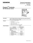
Standard Type
(See Figure 1)
Figure 1. Standard Type.
Page 2
Siemens Industry, Inc.