1
HANDLING
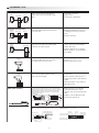
1. General handling
3. Sticking aperture mask
Do not swing the photoelectric switch by the cable. Do not pull
excessively on the cable of the photoelectric switch.
Peel the back paper to stick the aperture mask (sold separately or
included). Fit the aperture mask outline to the sensing face. The
aperture mask might be peeled off if oil or dust is on the sensing face.
Be sure to wipe it before sticking.
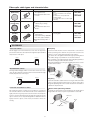
4. Precautions for handling fiber-optic switches
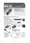
Mounting the amplifier
Mount the amplifier on the dedicated bracket (HPX-PA04, optional
part) or DIN rail.
Do not strike or scratch the sensing head.
1 Insert one rail of the bracket or DIN
rail into the slot at point A.
Do not use photoelectric switch fiber-optic cables made of plastic
where organic solvents are present.
Do not bend the fiber part of a fiber optic switch excessively or
subject it to unreasonable force.
2 Push the unit downwards until the
second rail clicks into place at point B.
When mounting the amplifier on the
DIN rail, always secure it with the
HPF-PA03 end plate (optional part).
Dismounting the amplifier
If the amplifier is pushed forward firmly
1 , the front lock will release.
The amplifier can then be pulled out
/2/ / a n d d e t a c h e d , a s s h o w n i n t h e
figure.
1
2
M3 max.
3
4
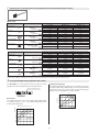
Head shape
M3/M4 screw
M6 screw
Cylindrical
In case of cylindrical head
5
Allowable tightening torque
0.8 N.m
1 N.m
0.3 N.m
1
2
3
If a fiber optic switch must be used where there is heavy vibration,
secure the fiber unit to prevent movement. Make sure that there is
no vibration where the fiber unit is coupled with the amplifier unit.
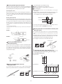
Peel the seal off the connector of the units to be attached.
Mount side by side on a DIN rail.
Slide the expansion units over to so that the connectors connect.
Use an end plate (HPX-PA03, sold separately) to hold the
expansion units in place.
When dismounting, slide each expansion unit off one by one.
4
5
Open the cover.
Move the fiber clamp lever forwards to the release position.
Firmly insert the tip of each fiber into the holes in the amplifier. For
the insertion depth of the fiber, refer to the reference mark on the
side of the unit.
Return the lever to the clamp position.
Close the cover.
2. Fiber-optic photoelectric switches in explosive gas atmospheres
Fiber unit structure transmit only light beam. Since optical energy
does not act as an ignition source, the fiber unit normally can be
installed in the hazardous area, and the amplifier unit can be installed
in a non-hazardous area. Before use, check the explosion-proof
requirements for facilities or equipment.
Fiber unit
2
Inserting optical fibers into the amplifier
Typical values are shown. Refer to the specifications of each fiber unit
model for specified torque.
Hazardous area
1
Expansion-unit attachment to the main unit for reduced wiring
models (HPX-AG/EG series)
Do not apply excessive tightening torque to the head a fiber optic
switch.
Setscrew: flat point or cup point:
B
A
1
5
4
2
3
Non-hazardous area
Amplifier
13
Fiber insertion depth reference mark